
Setup Guide — RGB 160xi and RGB 164xi
C
These instructions provide a quick setup guide for experienced installers. Installation
and service must be performed by authorized personnel only.
Step 1 — Disconnect power
Turn off all equipment and disconnect their power sources.
Step 2 — Configure sync settings
W
Changes to internal jumpers must be
performed by authorized service personnel
only. Take steps to prevent electrostatic
discharge.
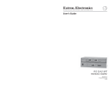
a. Open the interface and locate jumper blocks J20
and J40 (see the figure at right).
b. Set the sync polarity (jumper J20):
To force H and V output syncs to negative,
connect pins 1 and 2.
For output sync to follow input sync, connect
pins 2 and 3 (default setting).
c. Set vertical sync pulse width (jumper J40).
For a narrow V output sync pulse, connect pins
1 and 2.
For a wide V output sync pulse (default setting),
connect pins 2 and 3.
d. Replace the cover.
Step 3 — Mount the interface
The interface can be mounted on a desk, in a rack (RGB 164xi only), under a desk, or through a
desk. See the RGB 160xi and RGB 164xi User’s Guide for details.
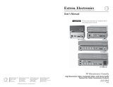
RGB 160
MIN/MAX
INPUTS
AUDIO ANALOG
BUFFERED LOCAL
MONITOR OUTPUT
UNIVERSAL INTERFACE W/ADSP
ON
NO MONITOR
NO MONITOR
1 2 3 4 5 7
H. SHIFT
6
N
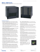
This figure shows the RGB 160xi front panel. The features of the RGB 164xi front panel are
similar.
Step 4 — Connect video input
Connect an RGBHV, RGBS, RGsB, or RsGsBs video input to the 15-pin HD input connector on
the front panel (
c
).
Step 5 — Connect audio input
Connect an unbalanced stereo audio source to the 3.5 mm mini
Tip-Ring-Sleeve (TRS) stereo audio connector (
b
) for unbalanced
audio input. Wire the plug as shown in the figure at right.
Step 6 — Connect local monitor
If required, connect a local monitor to this 15-pin HD connector (
e
).
The Extron
®
RGB 160xi and RGB 164xi interfaces accept
RGBHV video and unbalanced stereo audio input and
provide one buffered local monitor output, one balanced
or unbalanced stereo audio output, and one (RGB 160xi)
or two (RGB 164xi) remote video outputs.
J19
1
J40
1
J20
1
Front
Rear
Power Supply
J20: Sync
polarity
jumper
J40: Vertical
sync
width
jumper
Sleeve ( )
Ring (R)
Tip (L)
Negative
Follow
1
Wide
Narrow
1

Setup Guide — RGB 160xi and RGB 164xi (cont’d)
Extron USA - West
Headquarters
+800.63 3.9876
Inside USA / Canada Only
+1.714.4 91.1500
+1.714.4 91.1517 FAX
Extron USA - East
+800.63 3.9876
Inside USA / Canada Only
+1.919.86 3.1794
+1.919.86 3.1797 FAX
Extron Europe
+800.39 87.6673
Inside Europe Only
+31.33.453.4 040
+31.33.453.4 050 FA X
Extron Asia
+800.733 9.8766
Inside Asia Only
+65.638 3.44 00
+65.638 3.46 64 FAX
Extron Japan
+81.3.3511.7655
+81.3.3511.7656 FAX
Extron China
+400.883.1568
Inside China Only
+86.21.3760.1568
+86.21.3760.1566 FA X
Extron Middle East
+971.4.2991800
+971.4.2991880 FAX
© 2010 Extron Electronics. All rights reserved.
68-549-50
Rev. A
02 10
100-240V 0.5 A MAX
50-60Hz
UNITY
50%
100%
GAIN/
PEAK
SOG
DDSP
SERR
SPARE
L R
AUDIO
R
G
B
H
V
S
OUTPUT 2OUTPUT 1
R
G
B
H
V
S
8 109 13
11 12
N
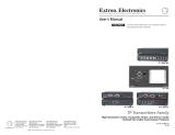
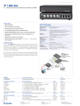
This figure shows the RGB 164xi rear panel. The features of the RGB 160xi rear panel are
similar except there is no Output 2 (
l
).
Step 7 — Connect video output(s)
Connect the RGBHV, RGBS, or RGsB video displays to Output 1 (
k
) and,
if required, Output 2 (
l
— RGB 164xi only), as shown in the figure at
right.
Step 8 — Connect audio output
Connect an audio device to the five-pole, 3.5 mm captive screw connector
(
m
). Follow the wiring diagram below for unbalanced or balanced stereo
output.
Unbalanced Stereo Output
Tip
NO GROUND HERE.
Sleeve(s)
Tip
NO GROUND HERE.
Balanced Stereo Output
Tip
Ring
Sleeve(s)
Tip
Ring
L R
L R
Left
Right
Left
Right
CAUTION
For unbalanced audio, connect the sleeve(s) to the center contact ground.
DO NOT connect the sleeve(s) to the negative (-) contacts.
Step 9 — Connect power
Connect a standard IEC AC power connector (100-240 VAC, 50-60 Hz) to this socket (
i
).
Power on input and output devices.
Step 10 — Set rear panel DIP switches
The first three rear panel DIP switches (
j
) control:
Sync on Green (SOG) — Set to on (up) for RGsB output; set to off for RGBHV or
RGBS output.
Digital Display Sync Processing (DDSP
™
) — Set to off (down) for sync processing; set to on
(up) for no sync processing (may be needed for some LCD and DLP plasma displays) .
Serration Pulses — Set to on (up) to keep serration pulses; set to off to remove them. If there is
flagging or bending at the top of the video image, set this switch to off.
N
Turning on the DDSP switch disables the horizontal shift.
Step 11 — Set rear panel Gain/Peak switch
This rear panel switch (
i
) can be set to Unity (no gain and no peaking), gain with 50%
peaking, gain with 100% peaking. For cable runs of 125 feet or less, use the Unity setting.
Step 12 — Set front panel DIP switches
These front panel ID bit termination DIP switches (
d
) must both be set to on (up) if using a
laptop and no local monitor. Both switches must be set to off if using a local monitor.
Step 13 — Adjust horizontal shift
This front panel knob (
f
) adjusts the horizontal shift of the remote output display device(s).
RGBS
Video
R
H
G
V
B
S
RGBHV
Video
R
H
G
V
B
S
RGsB
Video
R
H
G
V
B
S
SOG
DDSP
SERR
SPARE
-
 1
1
-
 2
2


Ask a question and I''ll find the answer in the document
Finding information in a document is now easier with AI
Related papers
-
Extron electronics RGB 160 User manual
-
-
Extron SMD 202 Owner's manual
-
Extron RGB 168xi User manual
-
Extron electronics RGB 192V User manual
-
-
-
 Extron electronics Network Router RGB 440 User manual
-
Extron RGB 468xi User manual
-
Extron electronics RGB 109xi User manual

Other documents
-
 Extron electronics Matrix 12800 Series User manual
-
 Extron electronics P/2 User manual
-
Extron electronic SW2 User manual
-
 Extron electronics TP T 15HD A User manual
-
 Extron electronics TP R BNC A User manual
-
-
 Extron electronics SW6 RGBHV User manual
-
-
 Extron electronics Stereo Receiver MTP R 15HD RSA D User manual
-
 Extron electronics DA4 User manual


