Gigabyte AGP 4X/8X User manual

Category
Motherboards
Type
User manual
When you installing AGP card, please make sure the following
notice is fully understood and practiced. If your AGP card has
"AGP 4X/8X (1.5V) notch"(show below), please make sure your
AGP card is AGP 4X/8X (1.5V).
Caution: AGP 2X card is not supported by Intel
®
845(GE/PE) / 845(E/
G) / 850(E) / E7205 / 865(G/PE/P) / 875P. You might experience system
unable to boot up normally. Please insert an AGP 4X/8X card.
Example 1: Diamond Vipper V770 golden finger is compatible with 2X/4X
mode AGP slot. It can be switched between AGP 2X(3.3V) or 4X(1.5V)
mode by adjusting the jumper. The factory default for this card is
2X(3.3V). The GA-8IPE775 Series (or any AGP 4X/8X only)
motherboards might not function properly, if you install this card without
switching the jumper to 4X(1.5V) mode in it.
Example 2: Some ATi Rage 128 Pro graphics cards made by "Power Color",
the graphics card manufacturer & some SiS 305 cards, their golden finger
is compatible with 2X(3.3V)/4X(1.5V) mode AGP slot, but they support 2X
(3.3V) only. The GA-8IPE775 Series (or any AGP 4X/8X only)
motherboards might not function properly, If you install this card in it.
Note : Although Gigabyte's AG32S(G) graphics card is based on ATi Rage
128 Pro chip, the design of AG32S(G) is compliance with AGP 4X(1.5V)
specification. Therefore, AG32S(G) will work fine with Intel
®
845(GE/PE) /
845(E/G) / 850(E) / E7205 / 865(G/PE/P) / 875P based motherboards.
Before you install PCI cards, please remove the Dual BIOS label from
PCI slots if there is one.
AGP 4X/8X notch
00
00
0 The author assumes no responsibility for any errors
or omissions that may appear in this document nor
does the author make a commitment to update the
information contained herein.
00
00
0 Third-party brands and names are the property of
their respective owners.
00
00
0 Please do not remove any labels on motherboard, this
may void the warranty of this motherboard.
00
00
0 Due to rapid change in technology, some of the
specifications might be out of date before publication
of this booklet.
May 14, 2004
Mother Board
GA-8IPE775 Pro/GA-8IPE775-G/GA-8IPE775
FCC Part 15, Subpart B, Section 15.107(a) and Section 15.109
(a),Class B Digital Device
DECLARATION OF CONFORMITY
Per FCC Part 2 Section 2.1077(a)
Responsible Party Name:
Address:
Phone/Fax No:
hereby declares that the product
Product Name:
Conforms to the following specifications:
This device complies with part 15 of the FCC Rules. Operation is
subject to the following two conditions: (1) This device may not
cause harmful and (2) this device must accept any inference received,
including that may cause undesired operation.
Representative Person’s Name:
Signature:
Eric Lu
Supplementary Information:
Model Number:
17358 Railroad Street
City of Industry, CA 91748
G.B.T. INC. (U.S.A.)
(818) 854-9338/ (818) 854-9339
Motherboard
GA-8IPE775 Pro/GA-8IPE775-G
/GA-8IPE775
Date:
ERIC LU
May 14, 2004
USER'S MANUAL
GA-8IPE775 Series
Intel
®
Pentium
®
4 Socket 775 Processor Motherboard
Pentium
®
4 Processor Motherboard
Rev. 1004
12ME-8IPE775-1004
- 2 -
GA-8IPE775 Series Motherboard
English
Table of Content
Warning ................................................................................................... 4
Chapter 1 Introduction ............................................................................. 5
Features Summary ...................................................................................... 5
GA-8IPE775 Series Motherboard Layout .................................................... 7
Block Diagram ............................................................................................. 8
Chapter 2 Hardware Installation Process ............................................. 11
Step 1: Install the Central Processing Unit (CPU)..................................... 12
Step 1-1: Installation of the CPU .................................................................................... 12
Step 1-2: Installation of the Heatsink .............................................................................. 13
Step 2: Installation of Memory ................................................................... 13
Step 3: Install expansion cards ................................................................. 16
Step 4: Install I/O Peripherals Cables ....................................................... 17
Step 4-1: I/O Back Panel Introduction ............................................................................ 17
Step 4-2: Connectors Introduction .................................................................................. 19
Chapter 3 BIOS Setup .......................................................................... 31
The Main Menu (For example: BIOS Ver. : 8IPE775 Pro.D4) .................. 32
Standard CMOS Features......................................................................... 34
Advanced BIOS Features .......................................................................... 37
Integrated Peripherals .............................................................................. 39
Power Management Setup ....................................................................... 43
Table of Content
English
- 3 -
PnP/PCI Configurations ............................................................................. 45
PC Health Status........................................................................................ 46
Frequency/Voltage Control ........................................................................ 48
Load Fail-Safe Defaults ............................................................................. 50
Load Optimized Defaults ........................................................................... 50
Set Supervisor/User Password .................................................................. 51
Save & Exit Setup ....................................................................................... 52
Exit Without Saving ................................................................................... 52
Chapter 4 Technical Reference ............................................................ 53
Flash BIOS Method Introduction............................................................... 53
2- / 4- / 6- / 8- Channel Audio Function Introduction ................................. 67
Jack-Sensing and UAJ Introduction .......................................................... 73
Xpress Recovery2 Introduction ................................................................. 75
Chapter 5 Appendix .............................................................................. 79
- 4 -
GA-8IPE775 Series Motherboard
English
Computer motherboards and expansion cards contain very delicate Integrated Circuit (IC) chips. To
protect them against damage from static electricity, you should follow some precautions whenever you
work on your computer.
1. Unplug your computer when working on the inside.
2. Use a grounded wrist strap before handling computer components. If you do not have one,
touch both of your hands to a safely grounded object or to a metal object, such as the power
supply case.
3. Hold components by the edges and try not touch the IC chips, leads or connectors, or other
components.
4. Place components on a grounded antistatic pad or on the bag that came with the components
whenever the components are separated from the system.
5. Ensure that the ATX power supply is switched off before you plug in or remove the ATX power
connector on the motherboard.
If the motherboard has mounting holes, but they don't line up with the holes on the base and there
are no slots to attach the spacers, do not become alarmed you can still attach the spacers to the
mounting holes. Just cut the bottom portion of the spacers (the spacer may be a little hard to cut off, so
be careful of your hands). In this way you can still attach the motherboard to the base without worrying
about short circuits. Sometimes you may need to use the plastic springs to isolate the screw from the
motherboard PCB surface, because the circuit wire may be near by the hole. Be careful, don't let the
screw contact any printed circuit write or parts on the PCB that are near the fixing hole, otherwise it
may damage the board or cause board malfunctioning.
Installing the motherboard to the chassis...
Warning
Introduction
English
- 5 -
CPU y Supports the latest Intel
®
Pentium
®
4 Socket 775 CPU
y Supports 533/800MHz FSB
y L2 cache varies with CPU
Motherboard y GA-8IPE775 Series Motherboard:
GA-8IPE775 Pro/GA-8IPE775-G/GA-8IPE775
Chipset y North Bridge: Intel
®
865PE
y South Bridge: Intel
®
ICH5
Memory y 4 184-pin DDR DIMM sockets
y Supports Dual channel DDR400/DDR333/DDR266 DIMM
y Supports 128MB/256MB/512MB/1GB unbuffered DRAM
y Supports up to 4GB DRAM (Max)
(Note 1)
Slots y 1 AGP slot supports 8X/4X(1.5V) mode
y 5 PCI slots
On-Board IDE y 2 IDE bus master (UDMA33/ATA66/ATA100) IDE ports for up to
4 ATAPI devices
y Can connect up to 4 IDE devices
On-Board Floppy y 1 Floppy port supports 2 FDD with 360K, 720K,1.2M, 1.44M and
2.88M bytes
On-Board Peripherals y 1 Parallel port supports Normal/EPP/ECP mode
y 2 Serial ports (COMA & COMB)
y 8 USB 2.0/1.1 ports (4 x Rear, 4 x Front by cable)
y 1 IrDA connector for IR/CIR
y 3 IEEE1394 (by cable)
y 1 Front Audio connector
y 1 PS/2 keyboard port
y 1 PS/2 mouse port
to be continued......
Chapter 1 Introduction
Features Summary
Due to chipset (Intel 865PE) architecture limitation, a FSB 800 Pentium 4
processor will support DDR400/DDR333/DDR266 memory module. A FSB 533 Pentium 4
processor will support DDR333 and DDR266 memory module.
(Note 1) Due to standard PC architecture, a certain amount of memory is reserved for system
usage and therefore the actual memory size is less than the stated amount.
For example, 4 GB of memory size will instead be shown as 3.xxGB memory
during system startup.
Only for GA-8IPE775 Pro.
- 6 -
GA-8IPE775 Series Motherboard
English
On-Board LAN y Build in Marvell 8001 Chipset (10/100/1000 Mbit)
y 1 RJ45 port
On-Board IEEE1394
y Ti TSB43AB23
On-Board Sound y ALC850 CODEC (UAJ)
y Supports Jack Sensing function
y Supports 2 / 4 / 6 / 8 channel audio
y Supports Line In / Line Out / MIC connection
y Surround Back Speaker (use of Surround-Kit to select)
y SPDIF In / Out
y CD In / Game connector
Serial ATA y 2 Serial ATA connectors (SATA0/SATA1)
y Controlled by ICH5
Hardware Monitor y CPU/Power /System Fan Revolution detect
y CPU/Power
/System Fan Fail Warning
y CPU Overheat Warning
y System Voltage Detect
I/O Control y IT8712
PS/2 Connector y PS/2 Keyboard interface and PS/2 Mouse interface
BIOS y Licensed AWARD BIOS
y Supports Dual BIOS /Q-Flash
Additional Features y Supports EasyTune
y Supports @BIOS
y Supports CPU Smart Fan Control function
Overclocking y Over Voltage (DDR/AGP/CPU) by BIOS
y Over Clock (DDR/AGP/CPU/PCI) by BIOS
Form Factor y ATX size form factor; 30.5cm x 24.4cm
Only for GA-8IPE775 Pro.
Only for GA-8IPE775-G.
Introduction
English
- 7 -
Only for GA-8IPE775 Pro.
Only for GA-8IPE775-G.
CD_IN
GA-8IPE775 (Pro/-G)
KB_MS
COMA
LPT
USB
LAN
ATX_12V
SOCKET 775
CPU_FAN
FDD
IDE1
IDE2
DDR2
COMB
PWR_LED
BAT
PCI1
PCI2
F_USB1
IT8712
MAIN
BIOS
CODEC
PWR_FAN
DDR3
F_USB2
INFO_LINK
F_AUDIO
IR_CIR
BACKUP
BIOS
DDR4
ATX
SYS_FAN
CI
DDR1
SPDIF_IO
SUR_CEN
R_USB
AUDIO
F_PANEL
GA-8IPE775 Series Motherboard Layout
GAME
P4 Titan
AGP
Intel
®
865PE
DUAL CHANNEL DDR
PCI3
Marvell
8001
PCI4
PCI5
SATA
F2_1394
F1_1394
TSB43AB23
CLR_CMOS
ICH5
SATA1
SATA0
- 8 -
GA-8IPE775 Series Motherboard
English
Block Diagram
Serial ATA
Channels
LGA 775
Processor
Intel 865PE
AC97
CODEC
ICH5
CPUCLK+/- (200MHz)
System Bus
800MHz
266/333/400MHz
ZCLK (66MHz)
HCLK+/- (200MHz)
66MHz
33 MHz
14.318 MHz
48 MHz
24 MHz
33 MHz
LPC BUS
AGP 8X/4X
AGPCLK
(66MHz)
5 PCI
PCICLK
(33MHz)
AC97 Link
MIC
LINE-IN
LINE-OUT
8 USB
(2.0/1.1)
Ports
ATA33/66/100
IDE Channels
Floppy
LPT Port
PS/2
KB/Mouse
COM
Ports
CLK GEN
ZCLK (66MHz)
CPUCLK+/- (200MHz)
AGPCLK (66MHz)
HCLK+/- (200MHz)
PCICLK (33MHz)
USBCLK (48MHz)
14.318 MHz
33 MHz
IT8712
Game Port
Marvell 8001
RJ45
24 MHz
ICH3V66 (66MHz)
DDR
TSB43AB23
IEEE 1394
Dual BIOS
Only for GA-8IPE775 Pro.
Only for GA-8IPE775-G.
Introduction
English
- 9 -
- 10 -
GA-8IPE775 Series Motherboard
English
Hardware Installation Process
English
- 11 -
To set up your computer, you must complete the following steps:
Step 1- Install the Central Processing Unit (CPU)
Step 2- Install memory modules
Step 3- Install expansion cards
Step 4- Install I/O Peripherals Cables
Chapter 2 Hardware Installation Process
Congratulations! You have accomplished the hardware installation!
Turn on the power supply or connect the power cable to the power outlet. Continue with
the BIOS/software installation.
Step 2
Step 1
Step 4
Step 3
Step 4
Step 4
- 12 -GA-8IPE775 Series Motherboard
English
Step 1: Install the Central Processing Unit (CPU)
Step 1-1: Installation of the CPU
Before installing the CPU, please comply with the following conditions:
1. Please make sure that the motherboard supports the CPU.
2. Please take note of the one indented corner of the CPU. If you install the CPU in the wrong
direction, the CPU will not insert properly. If this occurs, please change the insert direction
of the CPU.
3. Please add an even layer of heat sink paste between the CPU and heatsink.
4. Please make sure the heatsink is installed on the CPU prior to system use, otherwise
overheating and permanent damage of the CPU may occur.
5. Please set the CPU host frequency in accordance with the processor specifications. It is
not recommended that the system bus frequency be set beyond hardware specifications
since it does not meet the required standards for the peripherals. If you wish to set the
frequency beyond the proper specifications, please do so according to your hardware
specifications including the CPU, graphics card, memory, hard drive, etc.
HT functionality requirement content :
Enabling the functionality of Hyper-Threading Technology for your computer system requires
all of the following platform components:
- CPU: An Intel
®
Pentium 4 Processor with HT Technology
- Chipset: An Intel
®
Chipset that supports HT Technology
- BIOS: A BIOS that supports HT Technology and has it enabled
- OS: An operation system that has optimizations for HT Technology
Fig. 1
Gently lift the metal
lever located on the
CPU socket to the
upright position.
Metal Lever
Fig. 2
Remove the plastic
covering on the CPU
socket.
Fig. 3
Notice the small gold
colored triangle located
on the edge of the CPU
socket. Align the
indented corner of the
CPU with the triangle
and gently insert the
CPU into position.
Fig. 4
Once the CPU is
properly inserted,
please replace the
plastic covering and
push the metal lever
back into its original
position.
Hardware Installation Process
English
- 13 -
Step 1-2: Installation of the Heatsink
Fig.1
Please apply an even
layer of heatsink paste
on the surface of the
installed CPU.
Fig. 3
Please attach the power connector of the heatsink to the CPU fan header
located on the motherboard. Installation is complete.
Fig. 2
Place the heatsink atop
the CPU and then
secure each of the four
heatsink clips by
pressing downwards.
The heatsink may adhere to the CPU as a result of hardening of the heatsink paste. If the heatsink
is removed when this occurs, the CPU may become pulled from its socket with the metal lever
still in its locked position and result in damage to the processor pins. To prevent such an
occurrence, it is suggested that either thermal tape rather than heat sink paste be used for heat
dissipation or using extreme care when removing the heatsink.
(for detailed installation instructions, please refer to
the heat sink installation section of the user manual)
Before installing the memory modules, please comply with the following conditions:
1. Please make sure that the memory used is supported by the motherboard. It is
recommended that memory of similar capacity, specifications and brand be used.
2. Before installing or removing memory modules, please make sure that the computer
power is switched off to prevent hardware damage.
3. Memory modules have a foolproof insertion design. A memory module can be installed in
only one direction. If you are unable to insert the module, please switch the direction.
Step 2: Installation of Memory
- 14 -GA-8IPE775 Series Motherboard
English
1. The DIMM socket has a notch, so the DIMM memory
module can only fit in one direction.
2. Insert the DIMM memory module vertically into the DIMM
socket. Then push it down.
3. Close the plastic clip at both edges of the DIMM sockets to
lock the DIMM module.
Reverse the installation steps when you wish to remove
the DIMM module.
The motherboard supports DDR memory modules, whereby BIOS will automatically detect memory
capacity and specifications. Memory modules are designed so that they can be inserted only in one
direction. The memory capacity used can differ with each slot.
DDR
Notch
DDR Introduction
Established on the existing SDRAM infrastructure, DDR (Double Data Rate) memory is a high
performance and cost-effective solution that allows easy adoption for memory vendors, OEMs, and
system integrators.
DDR memory is a great evolutionary solution for the PC industry that builds on the existing SDRAM
architecture, yet make the awesome advances in solving the system performance bottleneck by doubling
the memory bandwidth. Nowadays, with the highest bandwidth of 3.2GB/s of DDR400 memory and
complete line of DDR400/333/266/200 memory solutions, DDR memory is the best choice for building high
performance and low latency DRAM subsystem that are suitable for servers, workstations, and full range
of desktop PCs.
Hardware Installation Process
English
- 15 -
GA-8IPE775 Series supports the Dual Channel Technology. After operating the Dual Channel Technology,
the bandwidth of Memory Bus will add double up to 6.4GB/s.
GA-8IPE775 Series includes 4 DIMM sockets, and each Channel has two DIMM sockets as following:
Channel A : DIMM 1, DIMM 2
Channel B : DIMM 3, DIMM 4
If you want to operate the Dual Channel Technology, please note the following explanations due
to the limitation of Intel
®
chipset specifications.
1. Only one DDR memory module is installed: The Dual Channel Technology can't operate
when only one DDR memory module is installed.
2. Two DDR memory modules are installed (the same memory size and type): The Dual
Channel Technology will operate when two memory modules are inserted individually into
Channel A and B. If you install two memory modules in the same channel, the Dual Channel
Technology will not operate.
3. Three DDR memory modules are installed: Please note that The Dual Channel
Technology will not operate when three DDR memory modules are installed; part of
them will not be detected.
4. Four DDR memory modules are installed: If you install four memory modules at the same
time, the Dual Channel Technology will operate only when those modules have the same
memory size and type.
We'll strongly recommend our user to slot two DDR memory modules into the DIMMs with the same color
in order for Dual Channel Technology to work.
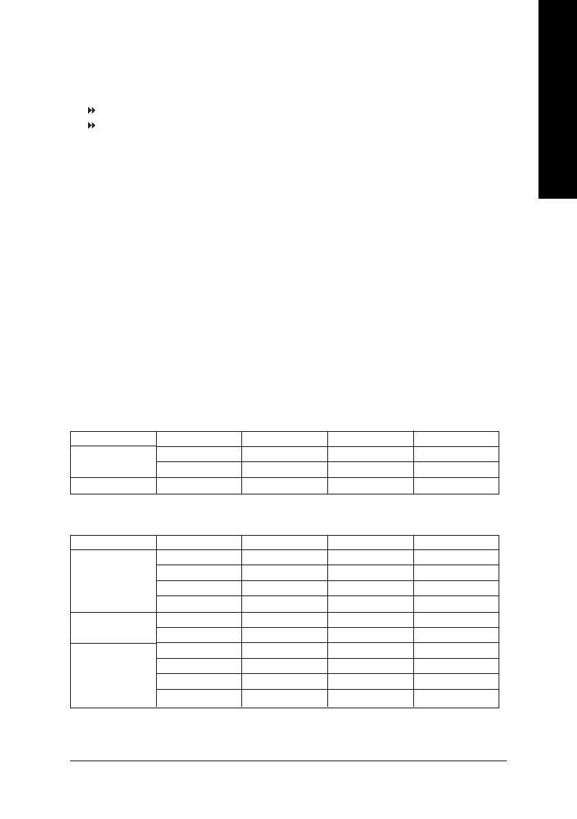
The following tables include all memory-installed combination types:
(Please note that those types not in the tables will not boot up.)
2 memory modules
4 memory modules
DIMM 1 DIMM 2 DIMM 3 DIMM 4
DS/SS X DS/SS X
X DS/SS X DS/SS
DS/SS DS/SS DS/SS DS/SS
z Figure 1: Dual Channel Technology (DS: Double Side, SS: Single Side)
1 memory module
2 memory modules
3 memory modules
DIMM 1 DIMM 2 DIMM 3 DIMM 4
DS/SS X X X
X DS/SS X X
X X DS/SS X
X X X DS/SS
DS/SS DS/SS X X
X X DS/SS DS/SS
DS/SS DS/SS DS/SS X
DS/SS DS/SS X DS/SS
DS/SS X DS/SS DS/SS
X DS/SS DS/SS DS/SS
z Figure 2: Don't operate Dual Channel Technology (DS: Double Side, SS: Single Side)
- 16 -GA-8IPE775 Series Motherboard
English
Step 3: Install expansion cards
1. Read the related expansion card's instruction document before install the expansion card into the
computer.
2. Remove your computer's chassis cover, screws and slot bracket from the computer.
3. Press the expansion card firmly into expansion slot in motherboard.
4. Be sure the metal contacts on the card are indeed seated in the slot.
5. Replace the screw to secure the slot bracket of the expansion card.
6. Replace your computer's chassis cover.
7. Power on the computer, if necessary, setup BIOS utility of expansion card from BIOS.
8. Install related driver from the operating system.
AGP Card
Please carefully pull out the small white- drawable
bar at the end of the AGP slot when you try to install/
Uninstall the AGP card. Please align the AGP card
to the onboard AGP slot and press firmly down on
the slot .Make sure your AGP card is locked by the
small white- drawable bar.
  • Page 1 1
  • Page 2 2
  • Page 3 3
  • Page 4 4
  • Page 5 5
  • Page 6 6
  • Page 7 7
  • Page 8 8
  • Page 9 9
  • Page 10 10
  • Page 11 11
  • Page 12 12
  • Page 13 13
  • Page 14 14
  • Page 15 15
  • Page 16 16
  • Page 17 17
  • Page 18 18
  • Page 19 19
  • Page 20 20
  • Page 21 21
  • Page 22 22
  • Page 23 23
  • Page 24 24
  • Page 25 25
  • Page 26 26
  • Page 27 27
  • Page 28 28
  • Page 29 29
  • Page 30 30
  • Page 31 31
  • Page 32 32
  • Page 33 33
  • Page 34 34
  • Page 35 35
  • Page 36 36
  • Page 37 37
  • Page 38 38
  • Page 39 39
  • Page 40 40
  • Page 41 41
  • Page 42 42
  • Page 43 43
  • Page 44 44
  • Page 45 45
  • Page 46 46
  • Page 47 47
  • Page 48 48
  • Page 49 49
  • Page 50 50
  • Page 51 51
  • Page 52 52
  • Page 53 53
  • Page 54 54
  • Page 55 55
  • Page 56 56
  • Page 57 57
  • Page 58 58
  • Page 59 59
  • Page 60 60
  • Page 61 61
  • Page 62 62
  • Page 63 63
  • Page 64 64
  • Page 65 65
  • Page 66 66
  • Page 67 67
  • Page 68 68
  • Page 69 69
  • Page 70 70
  • Page 71 71
  • Page 72 72
  • Page 73 73
  • Page 74 74
  • Page 75 75
  • Page 76 76
  • Page 77 77
  • Page 78 78
  • Page 79 79
  • Page 80 80
  • Page 81 81
  • Page 82 82
  • Page 83 83
  • Page 84 84
  • Page 85 85
  • Page 86 86
  • Page 87 87
  • Page 88 88
  • Page 89 89
  • Page 90 90
  • Page 91 91
  • Page 92 92
  • Page 93 93
  • Page 94 94
  • Page 95 95
  • Page 96 96

Gigabyte AGP 4X/8X User manual

Category
Motherboards
Type
User manual

Ask a question and I''ll find the answer in the document

Finding information in a document is now easier with AI