Page is loading ...

463241904 • 80001018 • 12-11-03

2 • 463241904
FOR YOUR SAFETY
1. Do not store or use gasoline or other
flammable vapors and liquids in the
vicinity of this or any other appliance.
2. An LP tank not connected for use shall
not be stored in the vicinity of this or any
other appliance.
FOR YOUR SAFETY
If you smell gas:
1. Shut off gas to the appliance.
2. Extinguish any open flame.
3. Open lid.
4. If odor continues, immediately call your
gas supplier or your fire department.
WARNING
CAUTION
For residential use only. Do not use for commercial
cooking.
Installation Safety Precautions
•
Not for use with LP gas.
•
National Fuel Gas Code, NFPA 54 / ANSI
Z223.1
National Electrical Code, ANSI / NFPA 70.
This grill is designed for natural gas use at 7 inch water column
supply pressure. Verify supply pressure with your local gas
company. If supply pressure is different than 7 inch, contact a
certified plumber for assistance.
Grill installation must conform with local codes, or in their
absence with
. Grill is not for use in or on recreational vehicles and/or
boats.
• All electrical accessories (such as rotisserie) must be
electrically grounded in accordance with local codes, or
Keep any
electrical cords and/or fuel supply hoses away from any hot
surfaces.
• This grill is safety certified for use in the United States only. Do
not modify for use in any other location. Modification will result
in a safety hazard.
DANGER
Safety Symbols
The symbols and boxes shown below explain what each heading
means. Read and follow all of the messages found throughout
the manual.
DANGER: Indicates an imminently hazardous situation
which, if not avoided, will result in death or serious injury.
WARNING
WARNING: Be alert to the possibility of serious bodily injury
if the instructions are not followed. Be sure to read and
carefully follow all of the messages.
CAUTION
CAUTION: Indicates a potentially hazardous situation which,
if not avoided, may result in minor or moderate injury.
Call Grill Service Center For Help And Parts
• If you need help or warranty parts call 1-800-241-7548 or send
a FAX to 1-706-576-6355.
Business hours: Open 24 hours – Seven days a week.
• To order non-warranty replacement parts or accessories (
) call 1-800-993-2677 or send a FAX to
1-706-565-2121.
grill
cover, cleaners, paint
WARNING
Combustion by-products produced when using this
product contain chemicals known to the State of
California to cause cancer, birth defects, and other
reproductive harm.
Model Number
Serial Number
Date Purchased
IMPORTANT: Fill out the product record information below.
See rating label on grill for serial number.

TABLE OF CONTENTS WARRANTY
For Your Safety ......................................2
Grill Service Center...................................2
Product Record Information ............................2
Installation Safety Precautions ..........................2
Safety Symbols......................................2
Warranty ...........................................3
Parts List...........................................4
Parts Diagram.......................................5
Assembly ........................................6-15
Use and Care ...................................16-23
Manufacturer warrants to the original consumer-
purchaser that this product shall be free from defects in
workmanship and materials under normal and reasonable
use and correct assembly (if assembled by consumer-
purchaser), from date of purchase.
Manufacturer will, at its option, refinish or replace any
product or part found to be defective during the warranty
period. Manufacturer will require you to return the part(s)
claimed to be defective, for its inspection, freight or postage
prepaid.
If you wish to obtain performance of any obligation under
this limited warranty, you should write to:
Manufacturer may require reasonable proof of purchase
and we suggest you keep your receipt. In the state of
California only, if refinishing or replacement of the product is
not commercially practicable, the retailer selling this product
or Manufacturer will refund the purchase price paid for the
product, less the amount directly attributable to use by the
original consumer-purchaser prior to discovery of the
nonconformity. In addition, in the state of California only, you
may take the product to the retail establishment from which it
was purchased or to any retail establishment selling this
product in order to obtain performance under this warranty.
This warranty does not include the cost on any
inconvenience or property damage due to failure of the
product and does not cover damage due to misuse, abuse,
accident, damage arising out of transportation of the product,
or damage incurred through commercial use of the product.
This express warranty is the sole warranty given by the
manufacturer and is in lieu of all other warranties, express or
implied, including implied warranty of merchantability or
fitness for a particular purpose. Neither Manufacturer dealers
nor the retail establishment selling this product has any
authority to make any warranties or to promise remedies in
addition to or inconsistent with those stated above.
Manufacturer's maximum liability, in any event, shall not
exceed the purchase price of the product paid by the original
consumer-purchaser. Some states do not allow the exclusion
or limitation of incidental or consequential damages. So the
above limitations or exclusions may not apply to you. This
warranty gives you specific legal rights and may also have
other rights which vary from state to state.
Brass burners - Lifetime
Stainless steel and die cast parts - 99 years
Electronic ignition - 10 years
Remaining parts - 2 years
Consumer Warranty / P.O. Box 1240
Columbus, GA 31902-1240
463241904 • 3

4 • 463241904
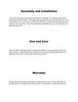
PARTS LIST – Model No. 463241904
Key Qty Description Part #
1 Grill Lid Assembly ...............80000414
A 1 Lid Insert........................80000415
B 1 Lid End Cap - Left ................80000416
C 1 Lid End Cap - Right ...............80000417
D 1 Lid Handle ......................80000418
E 1 Thermometer ....................80000096
F 1 Logo Plate ......................80000330
G 1 Grill Bottom Front Assembly.........80000688
H 1 Lower Grill Bottom Rear Assembly....80000423
I 1 Upper Grill Bottom Rear............80000425
J 1 Bottom End Cap - Right ............80000428
K 1 Bottom End Cap - Left .............80000429
L 4 Main Burner .....................80000431
M 1 Burner Brace/Carryover ............80000689
N 1 Manifold Heat Shield ..............80000437
O 1 Ignitor System Assembly ...........80000690
P 1 Control Panel ....................80001630
Q 5 Control Knob ....................80000354
R 1 Manifold/Hose/Regulator Assembly . . . 80000848
S 1 Wind Reflector Baffle ..............80000829
T 1 Sideburner Frame ................80000447
U 1 Sideburner Lid ...................80000316
V 1 Sideburner Pan ..................80000051
W 1 Sideburner Electrode ..............80000055
X 1 Sideburner Control Panel...........80001631
Y 2 Towel Bar .......................80000460
Z 1 Sideburner Assembly ..............80001035
AA 1 Side Shelf.......................80000457
BB 1 Side Shelf Panel..................80000459
1 Grill Bottom Assembly............80001635
1 Sideburner Shelf Assembly........80000446
1 Side Shelf Assembly .............80000456
Key Qty Description Part #
CC 1 Cart Side Panel Left ...............80000462
DD 1 Cart Side Panel Right..............80000467
EE 1 Cart Back Panel ..................80000469
FF 1 Bottom Shelf.....................80000847
GG 1 Bottom Rail......................80000472
HH 1 Door Assembly - Left ..............80000476
I I 1 Door Assembly - Right .............80000479
JJ 1 Door Brace ......................80000473
KK 2 Condiment Basket ................80000482
LL 2 Locking Caster ...................80000268
MM 2 Fixed Caster.....................80000269
NN 1 Grease Tray .....................80000483
OO 1 Grease Cup .....................80000270
PP 1 Grease Clip .....................80000271
QQ 1 SwingAway Warming Rack .........80000421
RR 3 Cooking Grate ...................80000445
SS 1 Sideburner Grate .................80000282
TT 1 Match-Lighting Stick...............80000274
UU 5 Knob Bezel......................80000034
VV 1 Caster Wrench ...................80000283
WW 1 AA Battery ......................80000284
XX 1 Sideburner Valve Clip..............80000455
YY 1 Natural Gas Hose.................80001030
1 Hardware Pack...................80001636
1 Product Guide ...................80001018

PARTS DIAGRAM – Model No. 463241904
463241904 • 5
A
B
C
D
E
F
G
H
I
J
K
L
L
M
N
O
P
P
Q
Q
R
T
U
V
W
X
Y
Y
Z
AA
BB
DD
CC
EE
DD
DD
CC
CC
FF
GG
HH
II
JJ
KK
KK
LL
LL
MM
MM
NN
OO
PP
QQ
RR
SS
TT
UU
Q
VV
WW
XX
S
YY
UU
UU
UU
Z

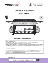
ASSEMBLY – Model No. 463241904
1
2
Assemble the two side panels to the bottom shelf using eight .
Leg braces must face inward toward each other. Front legs have two holes on the back side
just above the side panel. Secure legs beneath shelf with eight ,
, and .
1/4-20x2-3/8” bolts (DDD)
7mm flat washers (EEE)
7mm lock washers (FFF) 1/4-20 hex nuts (GGG)
Assemble back panel between rear legs using four ,
, and . Attach door brace to back side of
front legs using four .
#10-24x3/8” screws (HHH) 5mm
lock washers (III) 5mm flat washers (JJJ)
4.2x10mm self-tap screws (KKK)
6 • 463241904
Right
rear leg
EEE
FFF
GGG
CCC
Braces face inward
Bottom shelf
Door
brace
Back
panel
Right
side
panel
Back panel
HHH
JJJIII
KKK
Door
brace
Left
front
leg
Rear view
Vent holes to
right side.
Front
Front leg
Front leg
Holes here
No holes here
Vent holes to
right side.

3
4
463241904 • 7
Caster
wrench
Locking casters
on front legs.
Attach , non-locking
casters to rear legs. Tighten casters using the
caster wrench provided.
locking casters to front legs
This step requires two people to lift and position grill
head onto cart.
Carefully lower the grill head onto the cart between the
two braces. Align the two holes on each side of the grill
head with the two holes on each brace.

5
6
8 • 463241904
Secure grill head to leg braces using four ,
, and . Screws
must be attached from of grill head into brace.
1/4-20x3/4” screws (LLL)
7mm lock washers (FFF) 7mm flat washers (EEE)
inside
Do not fully tighten screws until side shelf and sideburner shelf
are assembled.
FFF
EEE
LLL
Place side shelf over right cart legs. Lip of shelf should fit between grill bottom and leg
brace. Secure shelf brackets to cart legs using two ,
, and on each bracket.
1/4-20x3/4” screws (LLL) 7mm
lock washers (FFF) 7mm flat washers (EEE)
CAUTION
SHARP EDGES! Wear gloves if necessary.
Side shelf
FFF
EEE
Repeat on front bracket
LLL

7
8
463241904 • 9
CAUTION
SHARP EDGES! Wear gloves if necessary.
Place sideburner shelf over left cart legs. Lip of shelf should fit between grill bottom
and leg brace. Secure shelf brackets to cart legs using two ,
, and on each bracket.
1/4-20x3/4” screws (LLL)
7mm lock washers (FFF) 7mm flat washers (EEE)
Fully tighten screws inside grill bottom at this time.
FFF
Repeat on front bracket
EEE
LLL
Sideburner
shelf
Remove the two screws (M4x10mm) and washers (4mm) from the
sideburner valve bracket.
Place sideburner valve under front of sideburner control panel so
that valve stem comes through large hole. Place sideburner bezel
over valve stem. Secure bezel to panel and valve using the two
screws and washers you removed from the valve bracket. Press
control knob onto valve stem.
Sideburner
valve
First, remove
screws and
washers from
bracket.
Valve stem
Sideburner bezel

10 • 463241904
9
10
Valve clip
Insert valve clip into small hole in bottom of burner, then snap other end of clip over sideburner valve. Place brass top on
sideburner, then place sideburner grate onto shelf.
Insert sideburner into shelf, placing end of burner over sideburner
valve. Valve should be in center hole of burner tube.
. Make
sure pin on bottom of burner is in center hole in shelf bracket.
Insert through holes in bracket and
into burner. Wrench-tighten. Attach ignitor wire to sideburner
electrode. Align cup cut-out with sideburner tube and holes in cup
bottom with double-sided screws.
Secure with
, and .
See
illustration below for correct burner-to-valve engagement
double-sided screws (MMM)
Place ignitor wire through
burner tube cutout in cup. 5mm flat washers
(JJJ) 5mm lock washers (III) #10-24 hex nuts (KKK)
Sideburner
Correct
burner-to-valve
engagement
Valve should be in center
hole in burner tube.
Ignitor
Wire
JJJ
III
KKK
MMM

11
12
Place cooking grates into grill bottom.
Grate wires running front to back
should be facing upward...side to
side wires downward.
Remove screws and washers from ends of towel bars. Insert screws from beneath shelf, through shelf holes and into ends
of towel bar. Repeat procedure on sideburner shelf.
Lock
washer
463241904 • 11
Flat
washer
Side-to-side
wires on bottom.

13
14
To assemble SwingAway, first insert
pivot wire into holes in side of grill lid.
Second, insert leg wires into holes in
sides of grill bottom.
Insert bottom door pin into hole in bottom
shelf. Press the top door pin down, align
with hole in door brace, release door pin.
Repeat procedure on remaining door.
SwingAway
CAUTION
SHARP EDGES! Wear gloves if necessary.
Press pin
on door top
12 • 463241904
Pivot
wire
Leg wire

15
16
Slide condiment baskets into brackets on back of both doors.
Hang the match-lighting stick and chain from the small
hook on the right side panel.
Condiment
basket
463241904 • 13

17
18
Slide grease tray into back of grill.
Place grease cup into grease clip. Hang grease clip from bottom of grease tray.
• Failure to install can in clip will cause hot grease to
drip from bottom of grill with risk of fire or property
damage.
CAUTION
Make sure drain hole
is on left side
14 • 463241904

Unscrew ignitor cap and place AA battery into ignitor slot with
positive end (+) facing outward. Screw ignitor cap onto ignitor.
+
–
AA Battery
19
20
463241904 • 15
Beneath sideburner control panel, thread the natural gas hose onto the fitting near the sideburner valve and wrench-tighten
the connection.
Natural
Gas Hose
Natural
Gas Hose
NOTE: Sideburner
control panel not
shown for clarity.
See Use & Care section for important
safety instructions. Please read “Connecting
Your Grill to the Natural Gas Source”, “Leak
Test”, and “Burner Flame Check” before
using grill.

16 • 463241904
USE AND CARE
DANGER
Connection should be made by a certified plumber. Supply the
plumber with a copy of these instructions. Incorrect
connection can result in a gas leak with possibility of fire.
WARNING
This grill is designed for natural gas use at 7 inch water
column supply pressure. Verify supply pressure with your
local gas company. If supply pressure is different than 7 inch,
contact a certified plumber for assistance. Not for use with
LP gas.
Connecting Your Grill to the Natural Gas Source
1.
2.
Figure A
A professionally-installed shut-off valve between the supply
piping and the socket is recommended, but not required, by
the National Fuel Gas Code. Socket connection must be made
outdoors.
Coat the gas supply pipe nipple with gas resistant dope or
teflon tape. Screw socket onto gas supply pipe (house gas
source) as shown in below, and wrench-tighten.
Quick disconnect socket
House piping
Figure A
Natural Gas Connections and Service Regulators
Above 1/2 psi.
Prior to 1998, all residual gas service regulators were
set with an outlet pressure of 7 inches water column.
In the 1998 edition of NFPA 54, the National Fuel Gas
Code, a change was made allowing service regulators
of 2 and 5 psi.
With this change it was also required that an in line
regulator be connected between the service regulator
and the appliance regulator if the 2 or 5 psi system is
used. This additional regulator is not supplied with the
product.
It is possible for a consumer, making the connection
themselves, or a plumber, not checking, to tap into a 2
or 5 psi line. If a pressure of 2 psi or greater is supplied
to the appliance regulator on certain grills it will shut
down and not deliver any gas to the grill. Other
concerns are the quick disconnect socket and hose
which are only rated to 1/2 psi.
If the quick disconnect socket, hose, and grill are
properly connected and still not getting gas, delivery
pressure needs to be verified. If pressure is greater
than 1/2 psi, make sure that an in line regulator is
present.
Once the grill has been over-pressured, the regulator
may or may not have been damaged. The best practice
is to replace the regulator.
3.
Figure B
Pull back the sleeve on the quick disconnect socket and insert
the unattached end of the gas hose into the socket. Release
the sleeve and continue pushing the hose into the socket until
the sleeve snaps into the locked position. See .
Figure B
Gas hose Sleeve
4.
Figure C
When the quick disconnect socket and the gas hose are
connected, a valve in the socket opens automatically to permit
full gas flow. When the gas hose is disconnected, the valve in
the socket instantly and positively shuts off the flow of gas.
Because the valve in the socket positively shuts off the flow of
gas, the grill can be disconnected from the gas source by
disconnecting the gas hose from the quick disconnect socket.
The socket should be left attached to the gas source (house
piping). , on the following page, shows properly
connected hose and socket.

463241904 • 17
Figure C
If a coupling is supplied with your gas hose, do not
attach the coupling to the quick disconnect socket for
connection to your house piping. Use of the coupling
will alter the gas flow, which may be a safety concern
under some circumstances. See Figure D.
The quick disconnect socket should never be connected
to the grill. Direction of gas flow is indicated on the
socket.
CAUTION
Figure D
With proper assembly, the gas hose cannot be removed
without pushing the quick disconnect sleeve back.
Please Note: Hose and assembly are C.S.A. listed for
natural gas, manufactured gas, mixed gas and for liquefied
petroleum and for LP Gas-Air mixtures on basis of 0.64
specific gravity for 1000 BTU’s per cubic foot of gas at 0.3
in. water column pressure drop. Only ANSI Z21.54 approved
hoses should be used with this grill.
To
disconnect, push sleeve back and pull plug out of sleeve (this
automatically shuts off gas).
The appliance and its individual shut off valve must be
disconnected from the gas supply piping system during any
pressure testing on that system at test pressures in excess
of 1/2 psig (3.5kPa).
The appliance must be isolated from the gas supply piping
system by closing its individual manual shutoff valve during
any pressure testing of the gas supply piping system at test
pressures equal to or less than 1/2 psi (3.5kPa).
WARNING
Do not use hard metal piping of any kind to connect this
type of grill to natural gas source. Use only hose
specified by manufacturer. Using hard metal piping or
convoluted metal tubing is an unsafe practice. Movement
of the grill can cause breakage of metal pipe.
Leak Testing
1. Turn all grill control knobs to OFF.
2.
3.
Correct before proceeding
4.
Be sure gas hose is tightly connected to gas source.
Completely open gas source. If you hear a , turn
gas off immediately. There is a major leak at the connection.
.
Brush soapy solution onto area circled below.
rushing sound
5. If “growing”
If leaks cannot
be stopped do not try to repair.
6.
bubbles appear, there is a leak. Close gas
source immediately and retighten connection.
Call for replacement parts.
Order new parts by giving the serial, model number and name
of items needed to the Grill Service Center at 1-800-241-7548.
Always close gas source after performing leak test.
NOTE: Sideburner
control panel not
shown for clarity.

18 • 463241904
WARNING
Ignitor Lighting
s
Turn on gas at gas source.
To ignite, turn left or right center knob to HI, push and hold
ELECTRONIC IGNITOR button.
If ignition does NOT take place within 5 seconds, turn all
burner valves to OFF, wait 5 minutes, then repeat lighting
procedure.
To ignite other burners, turn knob to HI adjacent to a lit burner.
Do not lean over grill while lighting.
1. Open lid.
2.
3.
4.
Lighting instructions continued on next page.
For Safe Use Of Your Grill And To Avoid Serious
Injury:
•
•
•
•
•
•
• Use grill at least 3 ft. from any wall or surface.
• Apartment Dwellers:
• NEVER attempt to light burner with lid closed. A buildup
of non-ignited gas inside a closed grill is hazardous.
Do not let children operate or play near grill.
Keep grill area clear and free from materials that burn.
Do not block holes in bottom or back of grill.
Check burner flames regularly.
Use grill only in well-ventilated space. NEVER use in
enclosed space such as carport, garage, porch, covered
patio, or under an overhead structure of any kind.
Do not use charcoal or ceramic briquets in a gas grill.
(
Maintain
10 ft. clearance to objects that can catch fire or sources of
ignition such as pilot lights on water heaters, live electrical
appliances, etc..
Check with management to learn the requirements and fire
codes for using a gas grill in your apartment complex. If
allowed, use outside on the ground floor with a three (3) foot
clearance from walls or rails. Do not use on or under
balconies.
Unless briquets are supplied with your grill.)
Safety Tips
s
s
s
s
s
s
s
s
s
When grill is not in use, turn off all control knobs and gas
source.
Never move grill while in operation or still hot.
Use long-handled barbecue utensils and oven mitts to avoid
burns and splatters.
Maximum load for sideburner and side shelf is 10 lbs.
The grease cup be attached to grease clip and emptied
after each use. Do not remove grease cup until grill has
completely cooled.
If you notice grease or other hot material dripping from grill
onto valve, hose or regulator, turn off gas source at once.
Determine the cause, correct it, then clean and inspect valve,
hose and regulator before continuing. Perform a leak test.
Keep ventilation openings in grill cart free and clear of debris.
The regulator may make a humming or whistling noise during
operation. This will not affect safety or use of grill.
If you have a grill problem see the .
must
"Troubleshooting Section"
CAUTION
• Putting out grease fires by closing the lid is not
possible. Grills are well ventilated for safety reasons.
• Do not use water on a grease fire. Personal injury may
result. If a grease fire develops, turn knobs and gas
source off.
• Do not leave grill unattended while preheating or
burning off food residue on HI. If grill has not been
regularly cleaned, a grease fire can occur that may
damage the product.

463241904 • 19
CAUTION
If burner does not light, turn knobs to , wait 5
minutes, and try again. If the burner does not ignite with
the valve open, gas will continue to flow out of the burner
and could accidently ignite with risk of injury.
OFF
Ignitor Lighting The Sideburner
Match Lighting
s Do not lean over grill while lighting.
1.
2.
3.
1.
2.
3.
To ignite sideburner, open sideburner cover.
Turn sideburner knob to HI, push and hold ELECTRONIC
IGNITOR button.
If sideburner does NOT light, turn knob to OFF, wait 5 minutes,
then repeat lighting procedure or use match.
To match light sideburner, open sideburner cover.
Place lit match near burner.
Push in and turn sideburner
knob counterclockwise.
Be sure burner lights
and stays lit.
Match-Lighting
s Do not lean over grill while lighting.
1. Open lid.
2.
3.
4.
Turn on gas at gas source.
Place lit match into match lighting stick, then into lighting hole
on right side of grill.
Push in and turn far right burner knob to HI. Be sure burner
lights and stays lit.
Light adjacent burners in sequence by pushing knobs in and
turning to HI.
Burner Flame Check
• Remove cooking grates. Light burner, rotate knobs from HI to
LO. You should see a smaller flame in LO position than seen
on HI. Always check flame prior to each use. Perform flame
check on sideburner. If only low flame is seen refer to "Sudden
drop or low flame" in the .Troubleshooting Section
HI
LO
Turning Grill Off
Ignitor Check
Valve Check
Hose Check
General Grill Cleaning
• Turn all knobs to position. Turn gas OFF at gas source.
Press and hold electronic ignitor
button. "Click" should be heard and spark seen each time
between collector box or burner and electrodes. See
if no click or spark.
. Knobs lock in position. To check
valves, first push in knobs and release, knobs should spring
back. If knobs do not spring back, replace valve assembly
before using grill. Turn knobs to position then turn back to
position. Valves should turn smoothly.
Before each use, check to see if hoses are cut or worn.
Replace damaged hoses before using grill. Use only parts
specified by manufacturer.
• Do not mistake brown or black accumulation of grease and
smoke for paint. Interiors of gas grills are not painted at the
factory . Apply a strong solution
of detergent and water or use a grill cleaner with scrub brush
on insides of grill lid and bottom. Rinse and allow to completely
air dry.
• Wash with warm soapy water and wipe dry.
Do not use citrisol, abrasive cleaners, degreasers or a
concentrated grill cleaner on plastic parts. Damage to and
failure of parts can result.
Because of glass-like composition, most
residue can be wiped away with baking soda/water solution or
specially formulated cleaner. Use nonabrasive scouring powder
for stubborn stains.
Wash with mild detergent or nonabrasive
cleaner and warm soapy water. Wipe dry with a soft
nonabrasive cloth.
To maintain your grill’s high quality
appearance, wash with mild detergent and warm soapy water
and wipe dry with a soft cloth after each use. Baked-on grease
deposits may require the use of an abrasive plastic cleaning
pad.
• Turn gas off at gas source.
• Important: Make sure gas is off at gas source before
checking valves
LO
•
(and should never be painted)
Do not apply a caustic grill/oven cleaner to painted
surfaces.
Plastic parts:
• Porcelain surfaces:
• Painted surfaces:
• Stainless steel surfaces:
"Troubleshooting"
s
OFF
OFF
OFF

20 • 463241904
Burner Valve
CAUTION
FACT: Sometimes spiders and other small insects climb into
the burner tubes attached to the burners. The spiders spin
webs, build nests and lay eggs. The webs or nests
can be very small, but they are very strong
and can block the flow of gas. Clean
burners prior to use after storing, at the
beginning of grilling season or after a period
of one month not being used.
NATURAL HAZARD • SPIDERS
Spider guards are on the air intakes in an effort to reduce this
problem, but it will not eliminate it! An obstruction can result
in a "flashback" (a fire in the burner tubes). The grill may still
light, but the obstruction does not allow full gas flow to the
burners.
Smell gas.
Burner(s) will not light.
A small yellow flame from burner (should be blue).
Fire coming from around or behind control knob.
Follow the “ ” instructions.
Clean burners often. Use a 12” pipe cleaner to clean out the
burner tubes. You may also force a stream of water from a
hose nozzle through burner tubes to clean them.
IF YOU EXPERIENCE THE FOLLOWING:
1.
2.
3.
4.
STOP!
Immediately turn off gas at gas source!
SOLUTION:
Wait for grill to cool.
Cleaning The Burner Assembly
Cleaning The Burner Assembly
Follow these instructions to clean and/or replace parts of burner
assembly or if you have trouble igniting grill.
1.
2. Remove cooking grates, grease tray and grease cup.
3. Remove cotter pins from beneath each burner "foot" using a
screwdriver or needle nose pliers.
4. Carefully lift each burner up and away from valve openings.
We suggest three ways to clean the burner tubes. Use the one
easiest for you.
Bend a stiff wire (a light weight coat hanger works well)
into a small hook. Run the hook through each burner
tube and burner several times.
Use a narrow bottle brush with a flexible handle (do not
use a brass wire brush), run the brush through each
burner tube and burner several times.
Use an air hose to force air into
the burner tube and out the burner ports. Check each
port to make sure air comes out each hole.
5. Wire brush entire outer surface of burner to remove food
residue and dirt.
6. Clean any blocked ports with a stiff wire such as an open
paper clip.
7. Check burner for damage, due to normal wear and corrosion
some holes may become enlarged. If any large cracks or
holes are found replace burner.
8. Carefully replace burners.
9. Replace cotter pin beneath each burner.
10. Replace grease tray, grease cup, and cooking grates.
Turn gas off at control knobs and gas source.
(A)
(B)
(C) Wear eye protection:
VERY IMPORTANT: Burner tubes must reengage valve
openings. See illustrations below.
Storing Your Grill
• Clean cooking grates.
• Store in dry location.
• Cover grill if stored outdoors. Choose from a variety of grill
covers offered by manufacturer.
• Store grill indoors ONLY if gas source is disconnected.
• When removing grill from storage, follow “
” instructions before starting grill.
Cleaning the Burner
Assembly
/