113201392

Craftsman 113201392, 113.201392 Owner's manual

  • Hello! I am an AI chatbot trained to assist you with the Craftsman 113201392 Owner's manual. I’ve already reviewed the document and can help you find the information you need or explain it in simple terms. Just ask your questions, and providing more details will help me assist you more effectively!
Serial
Number ............
ModeJ and serial
number may be found
at the rear
of the cabinet.
You should record both
model and serial number
in a safe place for
future use.
CAUTION:
Read
SAFETY
iNSTRUCTIONS
carefully
CRRFTSMRHo
295 AMP
DUAL RANGE
ARC WELDER
® assembly
® operating
repair parts
Sold by SEARS, ROEBUCK AND CO., Chicago, IL 60684 U,S.A.
Part No. 61341 _ :'_ ' . _ _,
SAFETY iNSTRUCTiONS TO OPERATOR
For your own protection, read and observe all instructions
mcluded nn this manual as well as the following specific
safety precautions.
1. PROTECTION FROM ELECTRICAL SHOCK
a. Do not let bare skin or wet clothing come between
the following combnnatlons
Electrode and Electrode Holder
Work Clamp Work Piece Metal Work Table
80 volts exast between these parts
when welder is onq I
Wear dry hole-free, clothing, gloves and shoes to
protect and insulate the body.
b Take special care to insulate yourself from ground
using dry =nsulatuon (such as dry wood} of adequate
s=ze when welding m damp Iocat,ons, on metal floors
or gratings, and in positions (such as s_tting or lying)
where parts or large areas of your body can be in
contact w_th possible grounds.
c. Manntain the electrode holder, work clamp, welding
cable and welding machine in good, safe operating
condition.
d. Do not use welding electrode as a cigarette hghter
e Connect the welder only to a source of electrical
power meeting the requ,rements, including
grounding, of the National Electrical Code (ANSI C1)
and local codes
f. Electrode coating may be eleetncaUy conductnve-
use welding gloves when ehangnng electrodes.
2. EYE AND BODY PROTECTION
a Use helmet, filter, and cover plate complytng with
ANSI Z87 1 to protect your eyes and face from
sparks and the rays of the arc when welding or
obserwng open arc weld=rig
b Always wear safety goggles with side shields
complying with ANSI Z87 1 when Jn a welding area,
or when near slag chipping operation
c. Wear od free protective garments, such as leather
gloves, heavy shirt, cuffless trousers and high shoes
d. Protect other near-by personnel w_th suitable
non flammable screening.
e Provide ddequdte ventilation in the welding area,
particularly when welding on galvanized, lead or
cadmeum plated steel, and other metal whtch produce
toxic fumes
f When worktng above floor level, protect yourself
from a fall should you get a shock. Never wrap the
electrode cable around any part of your body
g Do not weld m Iocat=ons close to chlorinated
hydrocarbon vapors com=ng from degreasmg.
cleaning, or sprawng operations The heat of the rays
of the arc can react with solvent vapors to form
phosgene, a highly toxic gas, and other irritating
products.
h. Unprotected specators must be kept clear of the
welding area doe to the harmful nature of ultra-wolet
and infra-red arc rays, welding sparks, and welding
fumes and gases
3. FLAMMABLE AND EXPLOSIVE MATERIALS
a. Remove flammable and explosive mater_al at least 35
feet from the welding arc to prevent welding sparks
or molten metal from starting a fire. Keep a type
ABC f_r_ extinguisher within easy reach
b,
Welding on or near containers wh,ch hold combustibles
can cause an expiosmn, even when they have been
cleaned For =nforn_atcon purchase "Safe Practtces for
Welding and Cutting Containers that Have Held
Combustrbles" (A6.0-65} from the Amerfcan Welding
Society 2501 Northwest Seventh St, Mnam_ FJorlda
33125
C.
When not welding, place the electrode holder where it
is _nsulated from the work clamp, work p=ece, or
work table. Accidental grounding can cause
overheating of the cables and wetder, creating a fire
hazard
d
Never connect the work cable or clamp to any object
but the work piece or metal work table. Connectnng
to other objects such as budding ground can create a
fire hazard
4. PREVENTATIVE MAINTENANCE
a,
Never apply power to the welder wnth any part of the
"cabinet" removed. Position on-off switch in "Off"
posltnon and disconnect welder from the power
supply before donng maintenance work inside the
machine. Removal of the welder cabinet should be
done only by a qualifned servnce techmcran
b. Before connecting the welder power cord to the
receptacle, check the following
1 Inspect the power cord and welding cables for cuts
or burns and make sure blades and ground pm on
the plug are stranght
2 Inspect "On-Off" sw_tch fever for cracks or broken
parts.
3 Inspect electrode holder law insulators for cracks
or broken parts
e. Never weld anything on or to the welder cabinet, as a
burn through may cause transformer failure
d
For additional safety information, purchase copies of
"Practice for Occupational and Educational Eye and
Face Protection" (ANSI Z87.1), "Safety _n Welding
and Cutting" (ANSI Z49.1), and "F_re Protection in
Use of Welding and Cutting Processes" (ANSI'NFPA
No 51B) from the Amerncan Natnonal Standards
[nstntute, 1430 Broadway, New York, N Y 10018
2
READ AND OBSERVE THE INSTRUCTIONS
APPEARING ON THE WARNING LABELS FOUND ON
THE INSIDE OF THE WELDING HELMET, SELECTOR
PLATE, AND CABINET,
_ARNIrJG Pro_e_t _ou,_lf and _ther_ R_d and
un_,stalld thl_ Idbel
_U',IES _rJD GASE_ _arl be _l_r,ge,v_s to _,l_r ne_h_
_pC RA' g _an 1nitre eves _nd bdrr, ,kin _LECTRIC
SHOCK, n r,ll
_ead _rd understand the m=m_fJ_l_r_, ,n,tr_¢tlons
n_ y_ur enlp_owr _fet, praCtl_eS
Feep y_ur he_d our _t th_ f_,,_es
U,e en_o@h vent,lab,on eqhust _ tb_ _rc o_ _oth
ro keep fu,_e_ and qase, rr_nl y_r ble_th,ng _one
and th_ _ner_l are_
Wea_ correct eye eor _ml uauy protect,on
See Am=r,_n p_uonal Sl_n_rJ Z49 I S_fel_ ,n
¢,eld, l_ _,1_ (urr,,_g m,_h,hall b, the ,_er,c_n
'_eld,nc Society 2501 _ 71h St "1_,_, FL_r,da
_3125 OSH& S,r_t_ a,lo H_lhh _ta_cla,_, ?gCFR
_910 _,l_b_e Tr_rn U _ D_pJrtn,e_l_ _f L_bar
,_asn,_l_n DC 2O210
O0 NOT _E_O. E THIS L_BEL
_AFTSMRn
12_ 0_fy for €_c1_ _ _ Pr_ecb0n
a_,_hr_l _nlU_o_ rays from _C _dhng
_,hPn _m_ lil_S _v_ce _mpacl re
3rid serI_L_SI_ reduce pt01_CllOn--
Inspe_l rr_quenll 7 ,_nd _mm_al_l_
_NOT REMOVE THiS L_L
LENS @
SHADENO
WARNING -- FOR YOUR SAFETY
REGARD;NG 80 VOLT pO'_ENTIAL
_HOCK AT ELECTRODE
R£GARDING POTENTIAL SHOCK 0_ CABI¢_ET
, _ u _ _ , _ ,. _ _ _
REGARDI_IG EYE _NJU_y
FIEGARDFNG F_ItE
WARNING" ARC WELDING CAN BE INJURIOUS TO OPERATOR AND PERSONS IN WORK AREA -
READ AND UNDERSTAND OWNERS MANUAL BEFORE OPERATING WELDER
FULL ONE YEAR WARRANTY ON CRAFTSMAN ELECTRIC WELDER
If this Craftsman Electrm Welder fails to perform properly, due to a defect in material or workmanship,
within one year from the date of purchase, Sears wdl repair It, free of charge
Warranty service is available by simply returning the welder to the nearest Sears store or Serwce Center
throughout the United States.
Th_s warranty gives you specific legal rights, and you may also have other rights which vary from state to
state.
SEARS, ROEBUCK AND CO
BSC 41-3
SEARS TOWER
CHICAGO. IL 60684
MATERIAL
;ELECTOR LOCKING KNOB
LECTRODE DIAMETER GAUGE
GETTING TO
KNOW YOUR
ARC WELDER
DUAL RANGE OUTLET JACKS
:TRODE CABLE AND
ELECTRODE HOLDER
WELDING
WORK CABLE AND
OPERATING INSTRUCTIONS
Safety Instructions to Operator
Warranty
Getting to Know Your Welder
Unpacking and Check m_ Contents
Assembly
TABLE OFCONTENTS
2
3
3
4
4
Operating Controls
Operating Instructions
Trouble Shooting
ARC WELD IT YOURSELF MANUAL
WELDING ROD SPECIFICATIONS
REPAIR PARTS
6
7
1-1
2-1
2=5
3
SPECIFICATIONS
Welding Range .............. 30 - 295 amps Hertz .............................. 60
Primary Volts (AC) ........ 230 Open C=rcult Volts (Max.) ................. 80
Amps Input (Max.) ................... 60 Duty Cycle ..................... 20% to 100%
Fuse Requ=red (Delayed Act=on Type) ......... 60 Etectrode Capacity .......... 1/16" thre 1/4"
Phase ....................... Single Over-all Dimensions .......... 21" x 14'" x 15"
UNPACKING AND CHECKING CONTENTS
SET-UP INSTR UCTIONS
Th_s Craftsman welder =s sh_pped complete _n one carton
In order to facd=tate packaging, certain =terns have been
removed at the factory and must be assembled when
received by the purchaser Remove all =terns from the
carton and =dent=fy =tern as shown m the exploded view
If'_l
,,,4:,:
1 2
WELDER _'_""'_ 4 5
_llustratton These "Loose Parts" should be accounted for
before discarding any packaging matertal
LOOSE PARTS LIST
Key
No. PartName Qty.
1
2
3
4
5
Welding Helmet(Partraflyassembled) .....
Helmetbandassembly{NotAssembled) . .
Electrodecableassembly .......
OwnersManual ..............
LoosePartsBag- Containingthefollowmg ttems
ElectrodeHolder .....
1/4" Hex"'L" Wrench .........
Work Clamp . ....
ElectrtaalOutletBox
Screw.Pan Hd Ty "AB" N'O"10x'1"/2 " ""
Outlet Box Cover ......
GroundTerminal
Screw,PanHd 10-32 x 1/2 ....
Lockwasher,No. 10 ....... :
Nut, Hex 10-32 ....
Connection Label .....
1
1
1
1
]
1
!
1
2
!
1
1
1
1
1
ASSEMBLY
TOOLS NEEDED
7/16-inch wrench Screwdriver (medluml
_r
ATTACHING ELECTRODE HOLDER
TO ELECTRODE CABLE
1. Grasp the electrode holder and locate the slotted head,
handle locking screw near the rind-point of the insulating
handle. Loosen th_s screw approximately two terns, or
until the handle can be shpped off the electrode holder.
DO NOT REMOVE THIS SCREW COMPLETELY
2. Sbde the handle off electrode holder and insert end of
electrode cable assembly through the handle.
The electrode cable =s the one with insulation stopped
from one end
3 Using the socke[he_d wrench Isupphedl back oet the
Hex head set screw, Ioca[ed near the end of electlode
holder untd the end of screw does not protrude into the
wire socket m the end of holder.
4. Make sure the wire strands on stopped end of electrode
cable have not been "frayed" Twist together with
fingers _f necessary.
5. Insert end of electrode cable into electrode holder and
tighten the socket-head set screw very hrmly usmg the
1/4" Hex "L'" Wrench furnished
4
6 Slide the handle back into place on electrode holder and
pos_t_on tt untd the hole m handle _s d_rectly over the
head of handle locking screw TLghten the screw
clockwise _ lust enough to secure the handle on
electrode holder
ATTACHING THE WORK CLAMP
TO THE WORK CABLE
1 Attach the terminal on the end of the work cable to the
work clamp•
2 Do not use e_ther of the holes m handle ends of work
clamp.
3 T_ghten the screw hrmly enough to insure good contact
and prevent the cable terminal from shppmg on the
clamp.
4 Remove octagon shaped electrical box from Loose Parts
Bag
Attach _he box to the rear of the we_det cabinet _th
the two sheet metal screws provided These screws must
be bght
Attach the ground terminal to the wall of the electrical
box as shown using zhe 10-32 nut, screw and Iockwasher
provided This connection must be t_ght
%
CONNECTING WELDER TO POWER SOURCE
CAUTION: 0o not attempt to connect this
welder to a regular household outlet. Make sure
the power-line voltage and frequency agree with
ratings shown on the selector plate attached to
top of cabinet.
Electrical connections between the welder and 230-volt,
single-phase, 60-cycle AC power source should be made by
a qualified electrician, A_| wiring must comply with the
National Electrical Code (ANSI C1) and The Local
Electrical Code,
1. install an individual (separate) line for the we[der with a
fuse block m the hne. For best results, this circuit should
be as short as possible. The size of the leads will depend
upon their length as shown in the table below
Supply Conductor (incl. Extension Cords)
Up to 50 feet ................. No. 8 AWG Copper
Over 50 feet ................. No. 6 AWG Copper
NOTE: -- These conductor sizes are for use with _ wP]der
having a rated input not more than 60 amps at 20% duty
CONNECT rO GROUND BURS
IN POWER £ANEL.
CONNECT TO HOT WIRES OF
A SINGLE PHASE SYSTEM, ONLY,
MAKE CONNECTIONS INSIDE
OUTLET BOX AND INSULATE
pERkY IN ACCORDANCE '/ITH
LOCAL CODE. INSTALL COVER,
cycle in accordance with Article 630 of the Nat_ona{
Electrical Code (ANSi CI) and may not be adequate for
other loads. Consult a quahfled electrician before us=ng for
other loads.
2, install 60 ampere fuses, of the delayed-action type such
as "Fustat'" or "Fusetron", m the fuse block
3. Connect 230-volt power hnes and ground as shown.
iii, ...............
OPERATING CONTROLS
The name "Dual Range" arc welder tsderwed from the fact
that your new arc welder =s equtpped with two separate
welding ranges.
?he be_jinner or less-experienced welder will f_nd the
30-200 amp range easier to use because it provides extra arc
stabdlty when welding with some of the "more d_fhcult to
weld with specralty rods" which are prone to pop-outs
The 40-295 amp range requires less line (input current)
draw for any given amp setting and permits the use of the
maximum amp settings w=th minimal effect on other
electncal appliances, motors, and hghts, on your electrtcal
system.
Either range may be used, depending on operator
preferences when the electrode diameter permits
REGARDING FIRE
KEEP C_tBU_TIBLES _JT OF RA_JGE _F V ELDI_G _FC_K_
USE FOR MINIMUM US_ FOR MAXIMUM
CONNECTING ELECTRODE
AND WORK CABLES
Insert the tapered plug on the end of the electrode cable
into the proper outlet jack depending on amperage required
or operato_ preference
To Insure a good electrical connectFon always twist the
electrode plug slightly whde inserting. To remove the plug
twist in the opposite direction whde removing.
NOTE: If you extend the welding cables beyond those
already supphed, they must be No 3 AWG or larger to
avoid an undue drop in welding current Do not extend
cables over 50 feet
%
Connect the work clamp to the mece to be welded, (to
complete the electrical circuit) or to the welding table rtself
provided it rs metalhc or wdl conduct electncl ty r
OPERATING iNSTRUCTiONS
We feel that weldtng wtth your new Craftsman dual range
arc welder isas s_mple as A B. C.
A Determine what diameter electrode should be used by
gauging the piece to be welded on the material thickness
gauge. The fractional number d_rectly beneath the bar
chart d_ctates what the proper electrode d_ameter is for
g_ven thicknesses of metals You wgl note that a specific
diameter of electrodes can be used on varying
thicknesses of mater_al, Th_s _s accomphshed by
adlustmg the heat selector for more or less amperage
/
B Next verdy the electrode diameter, by placing the bare
porbon of the electrode into the electrode d_ameter
gauge on the right s_de of the cabinet
Because electrodes are mass produced, there may be
smag burrs on the bare end of the electrode Make sure
the bare end of the rod _s as clean as possible for
accurate sizing
C Finally, determine the type of electrode by the
tdent_ficatlon on the package or by the American
Welding Soctety number stenctlled on the coated portion
of the electrode, bearing in m_nd the type of electrode
you have chosen - E6013 or E7014, and also _ts'
diameter (as prewously determtned)
Locate that band on the amp scale There are two E6013
bands and two E7014 bands, use the band which
coordinates w_th the amp range you have selected.
Now loosen the heat selector knob and move [he
pointer untd the fractional number matching your
electrode diameter appears m the pointer window.
Tighten the heat seEector knob
Insert the electrode cable mto the proper tack
(dependmg on the range selected) Connect the work
clamp to the work
Wear Welding Helmet.
Turn the On-Off swttch to the "ON" positron and you
are ready to weld.
Because metals vary m their make up and the techntque
of each operator [s different, you may find _t necessary
to increase or decrease the amperage output accordingly
CAUTION. Do not loosen and move heat selector whde
welding.
The duty cycle ratings bracketing the amperage scales are
provided for your convenience and protection of your new
welder Duty cycle is the performance level of the welder
based on a 10 m4nutehrnespan Fo_ example wetdlng for 6
minutes out of 10 minutes _s a 60% dut,, c,,,ele Tc a,c !
possible overheatlr_g of _he _e_dlng tTal,s{o_q_',_ ' _ h _'
could shorten the hfe of your ,velde_, Dc [.Jo7 v<.-._,J tr
duty c,/c_es t_ied ON "h_ r-213 _D'3_ _"
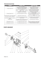
TROUBLE SHOOTING
WARNING:REMOVAL OF THE WELDER CABINET TOP FOR ANY
REASON MUST BE DONE BY A QUALIFIED SERVICE
TECHNICIAN.
TROUBLE PROBABLE CAUSE SUGGESTED REMEDY
1.
Fan and welder do not
operate, or continually
blow fuses.
Welding current low
or weak.
Can't hold an arc.
1. Improperly fused or
protected.
2. Blown fuse, or opeR
circuit breaker.
3. "ON-OFF" sw=tch not "ON".
1. Low line voltage.
2. Welding current
setting too low.
3. Poor connections.
1. Using a D,C, welding
rod
2. Low hydrogen rod.
2.
3
Use 60 ampere fuses of the delayed
action type such as "'Fusetron" or
"'Fustat" or 60 ampere 240 volt
mrcutt breaker.
Replace fuse, or reset the ctrcu_t
breaker
Turn switch "ON".
1. Have a voltage check performed by
the local power company.
2. Check current recommended for
the electrode being used.
3 Check electrode holder, work and
electrode cable connections.
1. Use ACor AC-DC rods
2. Use rod of 3!16-inch maximum
d=ameter, or smaller on 30-200
amp range or lower
SERVICE TIPS
FAN MOTOR:
No provision has been made for lubricating the fan
motor, as extra large otl reservoirs provide lubrication
for the hfe of the motor.
SELECTOR PLUGS OR CONTACTS:
WARNING: BE POSITIVE YOU HAVE DISCONNECTED
THE POWER SUPPLY TO THE WELDER.
DO NOT REMOVE CABINET TOP OR
SELECTOR PLATE.
If for any reason the selector plugs or mating contacts
become burned or pitted, they should be cleaned with a
fine grade of emerycloth or dressedvery bghtly w=th a
fine file.
8
t:RRFTSMRNo
A COMPREHENSIVE
GUIDE FOR YOUR
NEW CRAFTSMAN
ARC WELDER AND
WHAT iT WiLL DO
CONTAINS:
INFORMATION ABOUT
VARIOUS TYPESOF RODS
USEFUL ACCESSORIES
TIPS ON CUTTING° WELDING
AND BRAZING
J
Form No. SP574-4 _'_
r.._o_.;__ _,_ __ ,_j_ ___,_ ,L_ .
TABLE OF CONTENTS
Page
Your Welder and What It Will no ............. 1-3
How the Craftsmen Contact Rod Simplifies Welding 1-3
Wkat Happens When You Weld? .............. 1-3
Read Before Welding ...................... 14
Learn By Doing .......................... 1-5
Position Welding ......................... t-t 1
Cest-lron Welding ........................ 1.14
Hsrd Surfacing Worn Cutting Edges .......... 1-15
The Twin Carbon Arc Torch .............. 1-16
Cutting and Other Milcellaneo=JsOperations , .. !-17
Inert-Gas Metal*Arc Welding ................ 1-19
Read this Manual carefully for additional welding information.
SEARS, ROEBUCK AND COMPANY
AND SIMPSONS-SEARS LIMITED
1-2
YOUR WELDER and what it will do..,
Your CRAFTSMANArc Welderisasturdilyconstructedandthoroughlytestedmachineengineeredto
give many years of efficient trouble-free service.It is listed by Underwriters' Laboratories,
incorporated,which meansthat it passesall requirementsof safety, fire hazardandtemperaturerise
limitsasspecifiedintheir Standardfor Transfer-TypeArc-WeldingEquipment.
HOWTHE CRAFTSMAN ELECTRODE
SIMPLIFIES WELDING
Craftsman Contact Electrode is self-starting--plusautomatic
restarting... The electrodestartsoncontact.
CraftsmanContact Electrode is self-cleaning ... Under nnrmai
conditionsthe slagremovesitselfastheweld cools.Spatterisalmost
non-existent. Craftsman Contact Electrode has an exceptionally
good appearance .., With fine ripple, unusually clean,smooth
appearance,and reducedslaginclusions.
CraftsmanContact Electrodedepositsmoremetalfaster.., Because
the powderedironin theflux goesintothe weld.
W H AT H A P P m=N S VHEN YOU WELD?
1 Beth edges of the metal
are heated by the arc,
until --
3 more molten metal and
flux is added from the
rod, which--
2 they melt and flow te-
EetherforminE onepiece,
instantly--
4[ fills the crater and covers
the top of the weld with
slag.
5 This process continues the entire length of the weld,
Arc Welding is the process of fusing two or more pieces of
metal together to form one piece. It is c=ccompiished by
heating adjacent metal surfacesto the melting point with an
electric arc, then adding o sufficient amount of molten
metal to provide reinforcement and fill any vacant space
between the parts being joined, as shown in the accompany-
ing illustrations.
The arc is created when an etectrlc current, regulated by
a welding transformer, flows across an air gap between an
electrode and the work being welded. The intense heat
generated by the arc is ideally suited for welding, c=sit
can be directed to affect only the part of the metal to be
welded. Uniform heat from the arc, isacquired by keeping
its length the samefor a given rod size and current setting.
At the instant an arc is "struck", a portion of the base
metal directly beneath it, is melted, resulting in a small
pool of molten metal, some of which is forced out by the
blast of the arc and deposited along the weld path. The
depth of the crater thus formed, is the distance the weld
will extend into the base metal and is referred to as the
penetration of the weFd.
Some of the electrode (which consists of o metal rod sur-
rounded by a flux coating) is melted simultaneously with
the base metal and is carried by the arc to the liquid pool
This added metal combines with the base metat to form
the deposited weld.
During this operation a part of the flux coating burns off
and forms a gaseous smoke screen that completely en-
velops the arc, protecting the molten meta_ from harmful
effects of oxygen and nitrogen in the surrounding atmos-
phere. The remainder of the flux coating that melts is
carried to the molten pool where it mixes with the metal
to combine with various impurities. It then floats to the
surfaces to form a coating of slag which covers the de-
posited weld metal, protecting it from the atmosphere and
retarding its cooling.
_3
READ BEFORE /VELD|NG
o
_ AiUSTABLE SPECIAL
_ HEA, D LENS
BAND GASKET
CET_R
HEb_ET
LEATHER GLOVES
SPECTACLE TYPE
GOGGLES
SHOES
W1RE BRUSH
1/4-INCH
STEEL
SAW
HORSE
When operating a welder, certain precautions must
be taken to prevent minor injuries to yourself and
others. Although injuries may not be serious or per-
manent, knowing how to use the protective equip-
ment to safeguard against them is the first step in
learning to weld.
,/
/
HELMET SWINGS
UP TO
CLEAR THE FACE
C-CLAMP
GROUND
CABLE
The effects of heat and light given off by the arc, whde
electric welding, may be compared to that of the sun's rays.
Even greater precautions are necessary for electric arc
welding. Before starting a weld, caution anyone in the
immediate vicinity against looking at the arc. In case of
accidental eye iniury, contact a physician immediately
To protect the face and eyes a heat-resisting, hbreglass
helmet is used. The special lens, which allows the user
to view the arc safely, is inserted rata the framed opening
of the helmet The dear glass, which should be replaced
from t_me to t_me, protects the expensive special lens
from breakage and weld spatter. The _elmet is held firmly
_nplace on the head with an adjustable head band, thereby
leaving both hands free. A close-fittlng skuff cap should
be worn w_th the helmet. As the he)met _sused only when
actually welding, a t_ltmg arrangement permits _t to be
swung up clear of the face. When the welding _sresumed
a s|ight nad of the head tips the helmet down over the Face.
To protect the eyes further wh_le cleaning the weld, goggles
should be worn by the welder and others working around
him. Animals are also affected by the rays and should be
kept at a safe distance.
To safeguard the hands against heat and weld spatter,
gauntlet-type leather gloves s_ould be worn. A leather
jacket will give beiCer protection against the shower of
sparks than ordinary clothing. H_gh top shoes(not oxfords)
should be worn. If a great deal of welding is to be done,
foundrymen's shoes are best.
Precautions must also be taken to protect property and
equipment against fire. A large fire extinguisher shouTdbe
within easy reach. The we_dingarea should have a concrete
or cinder floor, kept dry and dear of inflammable rubbish.
Sometimes, it _s necessary to weld close to a fuel tank. If
practical, remove the part to be welded If not, dram the
tank and completely fill it w_th water.
Few tools, in addition to those supplied w_th the welding
machine, are needed and most of them can be found in
the average shop Two sawhorses supporting a 1/4-inch
steel plate makes an excellent welding table A permanent
bench, using the same steel plate, can be made of angle
iron or p_pe. A ch_pping hammer is used to clean slag off
a weld and phers will be useful for handling hot metak A
w_re brush _sused to dean the work before welding and
remove small pieces of slag after chipping.
Small pieces of todd-steel scrap iron, reasonably free of
rust and paint, should be used for prachce welding. Angle
iron, bar stock or plate steel are good examples. Do not
_ssescrap cast iron, high carbon or hardened steel as these
rneta|s require special electrodes and welding techniques.
These should be set aside for future practice after com-
pleting elementary practice lessons
LEARN BY DOING
OiRECTIOH
OF WELO
Expe_ience has proven that short periods of practice at
regular intervals are the best way to teach yourself how
to weld. As learning to weld is simply a process of trial
and error, all practice work should be done on scrap metal
that can be discarded. Do not attempt to make repairs on
valuable equipment until you have satisfied yourself that
your practice welds are of good appearance and free of
slag or gas inclusions. Remember, what you fail to learn
while practicing, must be learned through a series of
mistakes and rewelds later on.
A comfortable body position is important when learning,
as tensed muscles will result in fatigue and lack of contro].
Sit on a low stool and grasp the electrode holder in one
hand with the cable drawn across the lap. Allow enough
slack to move the holder freely and yet keep the weight
and drag of a long length of cable from becoming tiring•
The ground connection is as much a part of the welding
circuit as the cable and electrode holder. A poor ground
connection can render the best welding equipment ineffi-
cient. When using a table with a steel top, fasten the lug of
the ground cable toit securely with a bolt or C-damp, so that
any piece of iron placed on the table top will be propedy
grounded. If a steel table is not used, connect the ground
cable dlrecfly to the work wlth a ground clamp or bolt.
Select a fairly large piece of steel plate approximately
1/4-inch thick and clamp it to the table top to prevent it
from lifting, should the electrode stick or "freeze" when
Figure 1
To strike an arc, scratch the
end of the rnd on the plate
and then quickly raise ap-
proximately 1/8-inch.
90
first attempting to weld. Insert a small, mgd-steel welding
electrode in the electrode holder and connect the welding
cables to produce the heat specified by the CONTROL
panel. Connect the ground cable to the work and set the
indicator in the current range recommended for the
diameter of rod used.
Any method of bringing the tip of the rod in contact with
the work, then quickly raising it until there isapproximately
a 1/8*inch gap between the rod and the work, will start an
arc. The easiest way for a beginner to strike an arc is to
scratch the tip of the rod a short distance on the surface of
the work, as you would a match, then lift it (qulckly) the re-
quired 1/8-inch (fig. 1). Another method isto strike the work
a hard blow with the tip of the rod and allow it to bounce
up to form the arc gap. The important thing is to strike
the arc quickly and not al]ow the rod to remain in contact
with the work.
A common mistake often made by a beginner is to point
the rod toward the work and, after lowering the helmet,
feel slowly about until the tip of the rod touches the work.
This always results in sticking or "freezing" of the rod
which produces a direct short circuit. When this occurs the
rod can be loosened by bending it from side to side while
pulling on the holder (fig. 2). If this fails, turn the welder
off. The electrode must be released in a matter of seconds
to avoid unnecessary heating of the welder or damage to
the flux coating on the rod.
Figure 2
Should the rod stick or
"freeze" bend it from side
to side while puHingupward
on the rod holder.
\
\
\
\
_5
I I t_ *_ _._ _
// //
X.,'///J//I///'/f////_
F_ger_3"
To layaweldbeadonlytwo
movementsare used,down-
wardandinthe directionthe
weldisth be laid.
Figure 4
Watch the Weld puddle to
keep the slag from flowing
in front of it, causing inclu-
sions and gas pockets.
Figure 5 Figure 6
Fill the crater, when starting
a new rod by striking the
arc at A thee movng to B
and backto C position•
Te widenthe bead. work the
rod from si[le to side slight-
ly, with a slow. zigzagging
crescent-shaped motion.
If difficulty is experienced offer repeated attempts to
maintain an arc check the ground connection for proper
contact with the work. If this does not help, increase the
welding current. Also check the rod size, as larger rods
require higher current settings.
Practice striking and maintaining an arc for a few seconds,
then snap it out by rapidly pulling the rod away from the
work. Repeat this operation until the arc can be started
and the gap maintained as uniformly as possible. In a
short time you will find the arc length can be controlled by
the crackling or "frying" sound which may be recognized
by gradually shortening the arc until it sputters irregularly
as though it were going to "choke out" and stlck--then
slowly lengthening the arc by pulling the rod away from
the work until it snaps out. Somewhere between these two
extremes the steady crackling sound of a proper arc tength
will be heard.
To lay a weld bead, only two movements are used., o
steeay downward feeding of the rod to maintain the correct
arc length and a slow travel in the direction in which the
weld is to be lald (fig, 3). _/atch the weld puddle and
arc length, and move the rod steadily in a straight llne as
the back end of the crater fills up (fig. 4), The slight c=ngle
of the rod will keep the flux or slag flowing over the
deposited weld metal to form a protective coating. If the
rod is moved too slowly the slag will flow in front of the
puddle and be trapped in the weld, producing inclusions
and gas pockets.
Lay a bead approximately four incheslong. After allowing
it to coot slightly, remove the slag coating, which covers the
top of the weld, by scraping along each edge of the weld
with a cold-chisel to]owed by wire brushing until it is bright
and clean, inspect the surface of the weld carefully before
starting another. The surface of a good weld is rippled
uniformly, which results from o steady rate of travel and
uniforrr arc length.
If the scrap plate usedis small, it will become very hot after
laying a few beads. This will alter welding conditions
which could be very confusing to a beginner. Have several
scrap pieces handy so each mc_ybe allowed to cool before
laying a second bead.
When starting with a new rod, chip slag from the crater
and strike 'i-he arc at the forward end as shown at "A'" in
figure 5. Then move the rod to B and back to C, a
about twi_e _ fi0t_ai raf_ of travel to give the rod a_d
base _et_l tim_ t0:_f up T0r proper fusion.
After laying a number of beads, try "working" the rod
from side to side slight y (fig. 6). This movement should
be slow and not wider thcsnthe diameter of the rod being
used. Experiment with different current settings, rod sizes
and rates of travel. Compare results with welds shown in
the diagrams (fig. 9).
Too low a current setting tends to deposit the bead on top
of the plate with very little penetration. The arc sound wi[[
be an intermittent crackle with irregular sputtering. Too
high a current setting (for the size of the rod oeing used)
will provide sufficient penetration but the bead will be thin
ana undercut in places. The arc makes a hissing sound and
the rod becomes red hot before it is half used.
If travel is too slow it will pile up a wide, heavy bead with
good penetration but with overlap of the weld metal on
sideswithout fusion. A large area surrounding the weld is
heated to a high temperature which produces distortion,
even on a stmple weld. If the rod is moved too fast the
small bead will result with little more thor melted base
metal. An extremely"long arc causes the rod to melt off in
globules, with litrle or no penetration, and a very irregular
weld surface. The arc produces a hissing sound.
A good weld laid with correct current setting, speed and arc
length will produce a surface that is rippled uniformly, with
the same width throughout its length, and well formed
crater. The cross-sectlonal view shows it to have good pene-
tratlon and no undercut or overlap.
Figure 7
Lay the weld beads about
one inch apart, gemove the
slag and examineeach wed
before starting the nexL
Figure 8
A pad of welfl metal isbuilt
up by running a series of
beads in layers at right
angtes to each other.
CURRENTTOOLOW
Arcis difficult to maintain.
Verylittle penetration.High
bead.
T_AVELTOO FAST
Sman bead undercut in
some p_aces. Rough top
and little penetration.
CUREEHTTOO HIGH
Wide thin head, undercut.
Crater pointed and long,
Rod burns elf very fast.
ARC TOO LONG
Surface ef weld rough.
Rod melts off in globules.
Are makes hissing sound.
TRAm/ELTOOgLOW
Metal piles up, making a
wide heavy bead, over-
tapped at sides in places.
NORMAL CONDtTIONS
Uniform ripples on su_ane
of weld. Arc makes steady
crackling sound.
Figure 9
Practice laying beads approximately one inch apart until
a good we_d can be produced with all the different rod
sizes the welder wilt handle (fig. 7). After becoming pro_
ficlent in running a bead, build up a pad of weld metal
Clean each bead before laying the next and make sure
they are fused together (fig. 8). Run the second layer at
right angles to the first and the third at right angles to the
second, etc.,.until a pad approximately 1/2-inch thick has
been built up. This type of welding _sused to build up
round or flat surfaces or reinforce parts that are rusted thin.
To avoid distortion when building up the end of a shaft,
run the beads paralle! to the axis and lay each successive
bead on the opposite slde asshown by the numbered steps
in figure 10. Cover the entire shaft with weld metal for
the desired length. If the place to be welded is not at the
end of the shaft, weld around it and turn the shaft slowly
to keep the we|d puddle tn the flat position _fig. 11). Clean
off the slag after each bead, then machine the shaft to
proper size.
Figure 10
17
FLAT WELDING
nff 'lffiff.g_
vrt19
Figurel i
i ]lr
f p,.JLETWIELD
LAPWELD
TACK
WELOS
Fiat welding includes all types of joints in which the weld
ishorizontal, and the electrode isfed down as m the practice
welds of previous pages. The five types of joints in figure 1
can be welded in the flat position.
Butt welds on light material should be practiced first on
scrap stock. Use 16-gauge mild steel sheet metal (approxi-
mately 1/16-inch thick) and 5/64-inch rods wqththe welder
set at approximately 30 to 50 amperes. Butt edges of metal
together and tack-weld approximate]y every three inches
(fig. 2). (Tack welds are small beads 1/4 to 3/8-inches in
length.) Place bars of scrap iron under ends of the work to
provide an air space above the table. Simply move the rod
in a straight line directly above the edges to be (greed
If the weld burns through in places, reduce the welding cur-
rent or increase the rate of travel. Some difficulty may be
experier_ced in starting the arc at these low current settings.
However, once the arc Js started, there will be sufficient
heat to make a sound weld. After laying a bead, turn the
work over and inspect the underside which should also have
a small uniform bead. To prevent burning through where
the edges are not butted t_ghtly together, move the rod back
and forth with short quick strokes in the dlrechon of the
weld to brTdge the gap and give the metal in the crater a
chance to solidify (fig. 3).
Butt welds on sheet metal hghter than 18 gauge should
not be attempted by the beginner without the use of a
back-up strip (fig 4) This consists of a bar of copper
clamped tightly against the underside ofthe seam to absorb
the heat of the arc and prevent the weld from burmng
through. To assure complete penetrahon with butt welds
on 8-gauge metal or heavier, a 1/16 to 3/32-inch gap
should be altowed between them (fig 5) Insert a wedge or
screwdriver between the plates when tack-welding to mare-
tam the gap, then turn the piece over, so the tack welds are
on the underside
Use enough current to melt edges of ploFes to o depth of
at least one-half their thickness Clean off the slag and
respect it for smoothness, penetration and height of rem-
forcernent A good weld should have a reinforcement shghtly
more than flush with the surface (f_g 6)- Turn the plate
SLIGHT
GAP
SHEET
METAL
L____I\
RACK-UP
STRIP
Frgure 4
Figure 3
Fcgure 5
Figure 7
t-.t-- GAP
FIRSTPASS
T_IRDPASS_ SECONDPA_S
REIHFORCING_ (WEAVE)
_PAS$BlrffWELD
Figure 8
E V-WELD
Figure 9
E-BEVELW£LO
Figure 10
over and weld a slm_iar bead on the other side (fig 71 A
hEgher welding current can be used on this s_de as there ws
no danger of burning through and fusion with the first
bead will be assured
Although butt welds can be made on steel plates up to
3/8-inch thick, with a 295-ampere machine using 1/4-inch
rod, the same results can be obtained with the 180 and
230-ampere machines if edges of plates are beveled (fig B)
Metal of almost any thickness can be welded m th_smanner
by depositing a number of beads, one on top of the other
until the groove _scompletely filled. If the plate can be
welded from both sides, always use a double bevet (fig. 9)
]f only one plate _sbeveled, the angle should be at 45 de-
grees fflg. 10).
1-8
UNDERCUT GASPOCKET
ENT
PENETRATION
Figure 11
Figure 12
Figure 13
Run the first pass on beveled plates with a 5/32-inch rod
and Jse as high a current as you can handle to obtain a
small bead on the underside. If this is not done, insufficient
penetration will result, as shown in figure 11. Be sure to
clean each pass before laying on the next. All beads are
laid by mowng the rod in a straight line with no weaving
or side-to-slde movement. On the last or reinforcing pass,
a weaving motion must be used to obtain a wide weld that
will completely cover oreceding beads. For the beginner,
the side-to-side movement .with a slight hesitation at each
end) will produce a smooth too without undercut or overlap.
Select several practice welds of different thicknesses and
cut them into 1-1/2-1nch strips. Clamp each strip in a vise
and bend it at the weld (fig. 12). If it breaks through the
weld, study it to find the cause of failure.
Corner welds are made on light sheet metal by running
a single bead along the top, after tack-welding at three-
inch intervals to prevent warping (fig. 13). If numerous gaps
are present, a back-up strip may be used. On heavier
metal two passes may be necessary and, if the design
permits, a smaller pass can be laid on the underside.
Beveling may be used to advantage on the thicker metals.
FILLET WELDS
WELD
II
BREAKING
THE WELD
Figure 4
Figure 6
Fillet welds are used to join two pieces of metal with sidesor
edges at right angles to each other. The size of such a
weld isbased on the leg length of the largest isoscelesright
triangle that can be inscribed within the cross sectional
area, as shown by the dotted-llne triangle (fig. 1). The
size of a fillet weld may also be measured with a square
and ruler, subtracting 1/32-inch from all dimensions under
3/16-inch and 1/16-inch from all over 1/4-inch (fig. 2).
For example, a 1/4-inch fillet weld should measure 5/16-
inch. This will offset any inaccuracy due to the slight radius
at the toe of the weld and allow for concavity of the bead.
When csfillet weld ]s stressed to its maximum capacity,
failure will usually occur through the throat section (fig. 3).
Therefore, the strength is determined by the throat dimen-
sion multiplied by the length of the weld. Finished welds of
this type should always be at least four times their size in
length; that is, a 1/4-inch fillet weld should never be less
than one inch long. The direction in which the load is applied
to a weld greatly affects its strength, which can be dearly
demonstrated by breaking the weJd (fig. 4). A ioint so
loaded should always be welded on both sides with fillets
equat to the plate thickness (fig. 5). If this cannot be done,
bevel the plate to assure complete penetration and position
the work at a 45*degree angle if possible.
For practice, tack-weld three pleces of scrap iron together
toform a cross (fig. 6). Use a 5/32-inch rod with high curren_
and hold it as indicated in the front and side views. Move
the rod at a steady even pace along the seam without any
slde-to-side movement and deposit one inch of weld for
each inch of rod melted. The surface contour of a good we_d
lr?
Figure 11
Figure 8
Figure 9
Figure tO
_UTTING
Figure 12
_ _ EXCESSWELD_
Figure 13
LAPWELDS
LAPWELDS
Figure 14 Figure 15
Figure+ 16
INTERMITTENT
WELOS
STAGGEREO
iNTER+
WELDS
Figure 17
WELD_'\OHBOTHSIRES
ATENDOFJOINT
should be nearly flat with a slight radius at the sides or
toes. Avoid excessive concave or convex surfaces of the
fillet (fig. 7). Undercuts and cold-laps are caused by not
holding the rod in the center of the seam (fig. 8). If the
desired fillet weld cannot be made with a single pass,
several passesare usedto build it upto required size(fig. 9).
Slag must be cleaned from each pass before depositing
the next. Fillet welds over 1/2-inch in size are rarely used
because ioints requiring more strength can be made more
economically by beveling and groove+welding, followed
by a small concave fillet weld to provide a radius in the
corner,
Horizontal fillet welding is used when the side or edge of
one member of the joint isinthe vertical positionparticularly
for small single-pass welds where the work cannot be tilted.
For practice, tack+weld two pieces of scrap together to
form a tee-jolnt (fig. 10). Use a 5/32-inch rod held at
angles indicated, and direct the arc into the corner ot the
joint. The arc length should be somewhat shorter than for
flat fillet welding. To assure penetration at the root, use the
highest welding current that ca_ be handled (fig. 11).
Good penetration is of prime importance and appearance
will come with experience. If the arc is advanced too fast,
or held too close to the vertical plate, undercutting may
result (fig. 12). Too slow travel will cause overlapping and
an extremely close arc or low current will produce a bead
with a convex surface (fig. 13). To check the penetration and
soundnessof the bead, break some of the welds for inspec-
tion, as shown in figure 4+
When making a lap weld, care should be taken not to mett
too much of the upper corner on the top plate (fig. 14).
Some melting will take place, but proper advance of the
rod will causethe weld metal to build up and blend into the
top surface. On sheet metal, hold the 3/32-inch rod almosl
perpendicular and move the arc rapidly. Welds of this
type should be wider than they are high, somewhat like a
flat beacJ(fig. 15). A sfight discoloration on the underside
of the lower sheet indicates good penetration. On heavy
metal, a 3/8+inch fillet weld can be laid in one pass with a
1/4-inch rod using a 295-ampere machine. However, with
smaller machines, the same weld or larger can be made by
building up with a number of passes (fig. 16). When
welding long narrow pieces, stagger the welds in short
intermittent beads, first on one side then on the other side,
to minimize distortion (fig. 17).
t-)O
POSUTION WELDING
WELD
In order to derive the greatest benefits from your welder,
you should practice until you can make a welded joint
in almost any conceivable position. The ability to do this
is especially useful when making repairs on machinery as
the amount of welding in most cases is small and does not
warrant disassembling the parts to weld them in the flat
position. Welds of this type have been classified into three
groups according to their location and are referred to as
vertical, horizontal and overhead welds (fig. 1). Of the
three positions,vertical welding will be used the most and
should be practiced first. Skill gained in this type of weld
will make horizontal and overhead welding easier.
VERTICAL WELDING
The two methods of welding in the vertical position are
commonly known as "vertlcal-down" and "'vertical-up"
welding (fig. 2). In the former the bead is started at the
top and welded in a straight line downward. In the latter
the bead is started at the bottom and welded up, usually
with a weaving motion.
The chief difficulty encountered with any position weld is
keeping the molten metal in the puddle from falling out,
To prevent this the arc mustbe held as short as possible and
the weld puddle kept fairly small so it will solidify rapidly.
Vertical-down welding isthe easiest to perform and is used
on material upto l/B-inch thick. Before attempting a vertical
weld, run a few practice beads to get the "feel" of the
arc. Tack-weld a piece of scrap iron to an old practice plate
so it is positioned vertically (fig. 3). Use 1/8-inch rods for
the first welds and a current of about 75 to 115 amperes.
Experiment with various amperage settings until you are
using the highest current you can handle. Hold the rod at
right angles to the plate laterally, with the tip pointed up
at the angle shown in figure 3. Start the weld at the top
of the plate and move the rod in a straight line downward.
The correct rate of travel can be determined by gradually
reducing the speed until molten metal in the puddle can no
longer be kept in place. Then, increase the speed slightly
while watching the puddle, arc length and angle of the rod.
A short arc provides better control of the molten metal.
Follow the same procedure with 3/32 and 5/32-inch rods.
It will be noted that the larger the rod the more difficult it
is to control the puddle. For this reason smaller diameter
rods are always used for position welding.
Lap or tee-joints are made by simply directing the arc into
the corner of the joint as in flat welding and moving the
rod down the seam at a steady pace. Butt welds may require
more practice, as there is a tendency to burn through on
light gauge material. If this occurs, continue until the seam
is completed and patch the hole by chipping the slag and
wire brushing until clean. Then, with slightly lower current,
strike an arc on the weld directly above the hole and quickly
bring the rod down to the lower rim of the hole to deposit
a small amount of metal. Raise the rod for an instant to
let the metal solidify and repeat until the hole is welded.
Hold a long arc when raising, so there will be no metal
deposited except when the rod is lowered. Any hesitation
in the rate of travel will cause a "burn through." If this
happens repeatedly, lower the welding current.
Leave a slight gap between pieces for butt welds on material
over 3/32-inch thick. Inspect the back side after welding
for small bead along the seam, indicating complete pene-
tration (fig. 4). Butt joints on material around 3/16-inch
thick should be welded on both sides.
Vertical-down welds may be made on heavier material by
laying in a number of passes (fig. 5), however, this practice
isnot recommended as ittakes longer than a heavier single-
pass weld made by the vertical-up method.
DOWNWELD
IRSD£_
VERTICAL-DOWN9_
_ure 3
/3RO PASS
-2gB PSi;
ASM,ALLS_ OP4
g_K SiDE|IIOBAWN
COIIPLET_P£WET_Tt0g
Figure 4
Figure 5
iii
VERTICAI..UP
WELDING
90°
Figure 6
Figure 7
Figure 8
r_
F;gure TO
Use 1/8 and 5/32-inch rods for all verticabup welds and
sta_" by running practice beads from bottom to top of a
3/16 or 1i4-1nch plate, tack-welded in a vertical position
Hold the rod as shown in figure 6, noting that the angle
of the rod is not as steep as for vertlcal-down welding, but
tdted just slightly (approximately five degrees) so the tip
of the electrode points upward. Strike and hold a short arc
until a small amount of metal _s deposited, then quickly
raise the rod upward w_th a wrist movement to increase the
length of the arc at the top of the stroke (fig. 7). As soon
os the metal deposited in the crater hessolidified, bring the
rod down and deposit more metal. Keep repeating this
whipping motion, while gradually moving the rod upward
and toward the plate as the electrode burns off. The length
of the stroke will depend upon the amount of metal de_
posited and the welding current used. Keep the rod in
constant motion once it has left the crater. The purpose
of a long arc is to prevent any metal from being deposited
except when the rod is held at the crater. If globules of
molten metal drop from the tip of the rod when the arc is
lengthened, either the current is too high or the rod has
remained away from the crater too lang. Care should be
taken not to break the arc Qt the top of the stroke. Do not
deposit too much metal at one time as this will cause the
weld to sag and result in a high narrow bead undercut
along the sides• Better penetration can be had by the
vertical-up method• This can be demonstrated by joining
two pieces of 3/16-inch metal with a butt weld, using the
whrpping motion. Leave a gap between the plates and use
a 5/32-inch rod with a fairly high current, determined by
experimenting. The whipping motion wifl melt the corners of
the plate and form a pocket in wh]ch to deposit the weld
metal (fig. 8).
Burn the rod in deep so the crater extends through to the
back side. After completing the weld, inspect the back
side for the smalt bead, whLch indicates 100-percent pene-
tration Buff welds on heawer materials should be welded
on both sides.
On materials up to 1/4-1nch thick, usethe whipping motion
on small single-passfillet welds for lap and tee-joints. Larger
single-pass fillet welds can be made by the whipping motion
with a slight slde-to-slde weave added and combined with
the up and down movement to make a triangular shaped
weave (fig. 9). This will produce a "shelf" upon which
additional metal is deposited intermLttentlyas the welding
progresses•There should be a slight pause in the weaving
mot_an at the toes of the weld to avoid making a bead that
is too convex. Materials 1/4-inch and thicker must be bev-
eled on one or both sides, depending upon the joint.
Practice making a wide bead using a side-to.side weaving
motion with a very shght whipping action at each end to
give the metal at each end a chance to solidify and avoid
undercutting along the sidesof the weld (fig. 10). This type
of bead is used on welds that require more than one pass
and iscolTed the finish bead or "wash" pass. Hold a short
arc, making the bead approximately 3/4-inch wide and
fairly hght, Multiple verticoLwelds may be made as shown
in the series of diagrams, figure 11.
÷
TOP_ I$!
Frgure I 1
r pASS
/