Amana ADW862EAB User manual

Category
Dishwashers
Type
User manual
BUILT- N DISHWAS
iNSTALLATION iNSTRUCT!ONS
LEAVEINSTALLATIONINSTRUCTIONSAND
USER'S GUIDEWITH OWNER
ALLELECTRICWIRINGANDPLUMBINGMUST BEDONE
IN ACCORDANCEWITH NATIONALANDLOCALCODES.
PRINTED]INUSA © 1999 - Maytag Corporation 6 915126B
TOOLSRECKSSAR¥FOR |NSTAL T|ON*
(2)RATCHET
O 3/16", 1/4", 5/16" SOCKETS
O PHILLIPSSCREWDRIVER
O STANDARDSCREWDRIVER
© WIRE CUTTERS
© CRESCENTWRENCH
© ADJUSTABLEPLIERS
© LEVEL
* (NotindMed: Toolsieqoitedfbr preparing
the cabi_et ope_ing).
UNCRAT|NG
SUPPORTACCESSORIES:
0 3/4" ULApproved Strain Rdief (proqded)
O 2 Appropriate Sized Wire Nuts
O 3/8" Male (NZT.) Compression Elbow
or Flare Elbow
O Thread Sealing Tape or Pipe Thread Compound
O Appropriate Sized Hoseqamp
O 2 Wood Mounting Screws (provided)
Water Hook-Up Kits Available:
(l_atel line wattl vane fitting Teflol_TM mile, tee valve litting)
5' BraidedStainless Stee! Part #19950153
5' Copper Part #19950152
Availablethroughan autlmrizedMaymgParts Retailer
Remove access and toe panels before beginning installation.
Remove bolts from the crate base brackets, _lsing 5/16" socket with ratchet. Remove crate base and
discard base and packaging. Until distlwasher is permanently instaDd, beware of opening the
door as the onk may tip forward.
Open the door and remove accessory package from silverware basket.
Remove any extra packing material from outside and inside the distlwasher This would include plug in water valve inlet.
Loosen front leg bolts wittl a crescent wrench. Adjust rear leg bolts in same mannei;
NOTE:Make sure you have everything
necessary for proper installation before
going to step 2.
_:: cmcal and watei facd_t_es should enter cabinet o_enm on the flooi o* th*ou ht]lle.,_ "1 " ' ...... ' " "' ' [ ' g ", " " g back or side walls,
?_< as shown in the shaded _ortion of the drawino. PreDrred drain outlet is shown in the _m_er _mrtion of the cabinet in drawing below.
Care should be taken to route phm*bing away from the motor and blower (if equipped). DONOT make connections until dishwasher
is in poskton Care should be taken to make sure cabinet hales for power cord and hoses have no sharp edges.
cabinet opening dishwasher dimensions
Preferred
DrainArea
Keel*back free
ofdrainwater& [
electricalSUl)!)ly Pt]eferred
I}ljailtArea
24" [
nn
33 3/4" (Min)
35 1/4" (Max)
CUSTOMPANELSAVAILABLEDishwasherscom_ with pre-instaHed pands. Custom pands are avaflaMe: stainDss steal and
trims kits for wood pands. See your authorized selling deMer for a complete list of products
available
WATER VALV
O Remove shipping plug from water hflet valve,
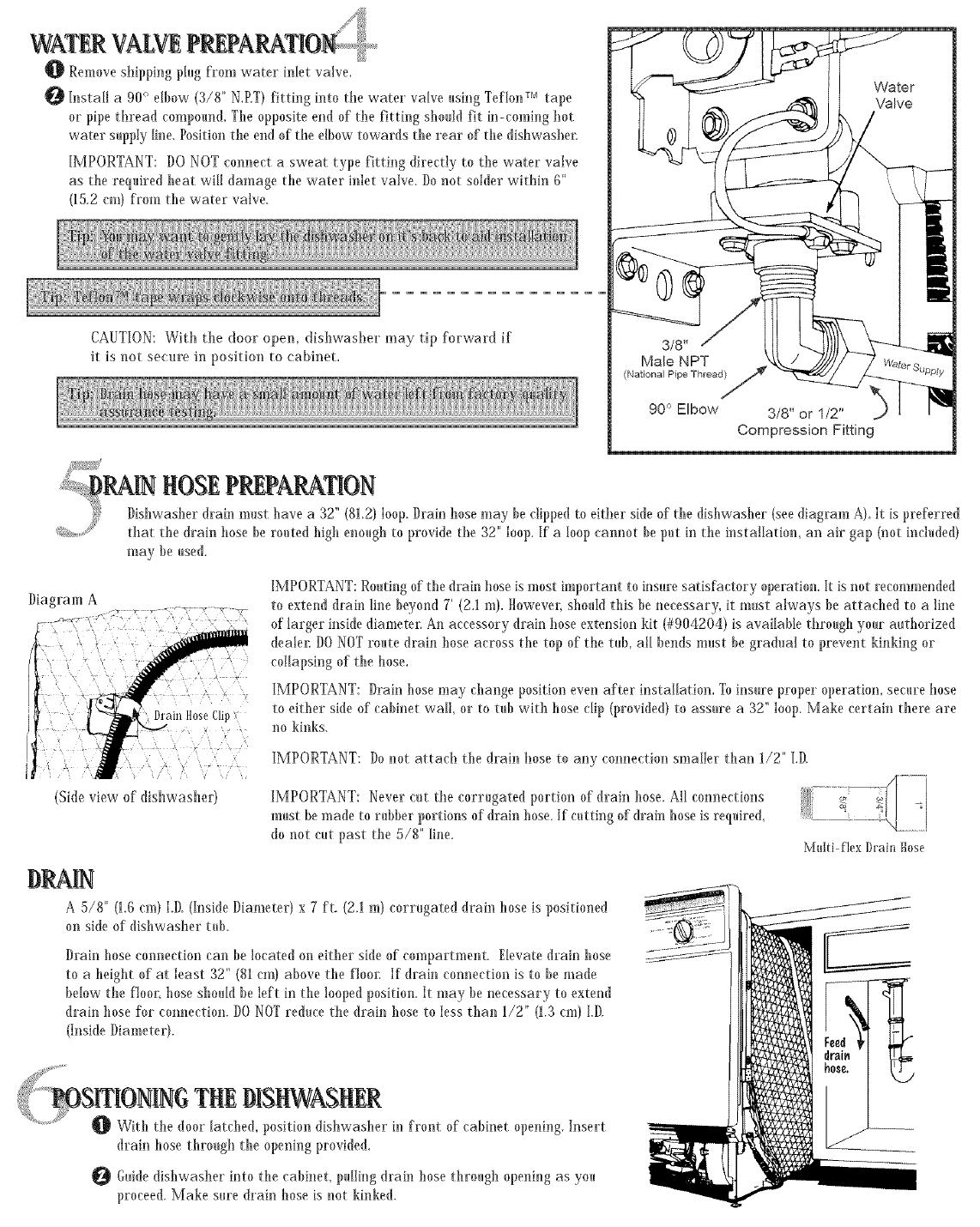
O Install a 90° elbow (3/8" N,P.T)fitting h,to the water valve using Teflon r'_ tape
or pipe thread compound. The opposite end of"the fitth*g should fit h_-eoming hot
water supply line. Position the end of the elbow towards the rear of the dishwasher
IMPORTANT: DO NOT connect a sweat type fitting directly to the water valve
as the required beat will damage the water inlet valve. Donot solder within 6"
(15.2 era) from the water valve.
CAUTION:With the door open, dishwasher may tip forward if
it is not se<ure in position to cabinet,
:, RAIR ROSEPREPARATION
_} Dishwasher drain must bave a 32" (812) loop. Drain hose may be clipped to either skle of the disbwasber (see diagram A) It is preferred
_,:_:.. that the drain bose be routed high enough to provide the 32" loop. If a loop eammt be put in the installation, an air gap (not included)
may be used.
Diagram A
IMPORTANT: Routing of the drain hose is most important to insure satisfactory operation. It is not recommended
to extend drain line beyond 7' (2.1 m). Howevei; sbou[d this be necessary, it must always be attached to a hne
of larger inside diametel: An accessory drain hose extension kit (#904204) is available through your autborized
dealel: DONOT route drain hose across the top of the tub, all bends must be gradual to prevent kinking or
co!lapsing of the hose,
IMPORTANT: Drain bose may change position even after installation, Toinsure proper operation, secure hose
to either side of cabinet wail, or to rob with bose dip (provided) to assure a 32" loop. Make certain there are
no kinks.
(Shleview of dishwasher)
IMPORTANT: I)o not attach the drain bose to any connection smaller than 1/2" I.D.
IMPORTANT: Never cut the corrugated portion of drain hose. All connections
must be made to rubber portions of drain hose. If cutting of drain bose is required,
do not cut past the 5/8" line.
-- .............. \
Mtflti flex Drain Hose
DRA|N
A 5/8" (1.6 era) LD (Inside Diameter) x 7 ft. (2.1 m) corrugated drain hose is positioned
on side of dishwasher tub.
Drain hose connection can be located on either Mde of compartment. Elevate drain hose
to a height of at least 32" (81 era) above the f'loox: If drain connection is to be made
below the floor; bose sbouM be left in the looped position. It may be necessary to extend
drain bose for connection. DONOT reduce the drain hose to less than 1/2" (1.3 cm) I.D.
(Inside Diameter).
+d+++_........
{ ' smoRIRG TRtDISRWASRtR
_1_ With the door latched, position dishwasher h* front of cabinet opening. Insert
drain bose through the opening provided_
Guidedisbwasher into the cabinet, puHh_gdrah_ hose through opening as you
proceed. Make sure drain bose is not kinked.
|OR|NG THEDISHWASHER(conUnued)
and horizontally. A combination of these
two adjustments are necessary to properly position the dishwasher and insure proper fit
of door m_d latch. Dishwasher must be LEVEL, solid, m_d square.
SECURINGTRE
Make pilot holes in the underside of counter and drive wood screws, provided in the
accessory paekag< through holes in the dishwasher mounting bracket. If part of
the bracket extends beyond the cabinet front, they may be trimmed with wire
cutters, provided sufficient material is left to support dishwasher mounting
Note: Dishwasher must be secured properly to
eountertop to avoid tipping when the door is open and
to prevent the tub from twisting,
It may be necessary to provide an additional
anehoring souree for mounting screws. Wood
strips across the top of dishwasher opening can be
used for solid surface or granite type eounte_s to secure the dishwas/[let_
D |N ROSE
If draining into the dispose_; check to make sure disposal plug has been removed.
If not, remove as shown,
With dishwasher in permanent position, damp drain hose to a properly sized
drain line.
THEF_CTREALCONNECF|ONS
SEE THE ELECTRICAL REQUIREMENTS SECTION
CAUTION: Verify power to dishwasher is off at source.
O Remove terminal box covet:
Ix order to secure the power supply cable, a ULlisted strain relief nmst be used to secure
the power supply to the back of tet'mina[ box,
Q Strip approximatdy 3/8" (.09 em) of"insulation fl'om incoming power supply wires. Connect
n ....... 27- ZZ
.2-_--_ ol
O Terminal I_o_
these wires to wires from dishwasher wire ]harness located in the terminal box. Connect
wires using the appropriate size wire nuts, twisting and tightening securely over the wire
connections. Connect white to white and black to black. Black to Black
Attach external grom)d wire frmn be]hindwasher of greet) grmmding screw. If an external
groundwh'e is used. insert the wire through the cable clamp and attach behind washer of
the green gro,nding screw. Attach the other end of external gro,nd wire to a s,itabie
external ground. If a question arises, refer to yore' local
electrical codes,
to White
Seem'e the strain relief and replace the termina! box covet:
StraiJJ Relief
IIOORUP
CHECKLOCALPLUMBINGCODESFORAPPROVEDPLUMBING
......... =PROCEDURESANDACCESSORIES.ALLPLUMBINGSHOULDBEDONE
IN ACCORDANCEWITH NATIONAL AND LOCAL CODES.
Connect water supply line to water valve, Minimum 3/8" 0.D.copper tubing or equivalent.
S}I[UTOFFVALVE:Instal[ a hand shutoff valve it) the water supply line ix an accessible location, such as m)der the sink The shutoff is optional,
but recmnmended and may be req_fired by local codes. Connections are pt'eferab[e located toward the left side of dishwasher: Care should be taken
to route plumbing away frmn motor and blower (if equipped), DONOT make these connections until the dishwasher is it) position,
Care s]houldbe taken to protect dishwas]herand water lines leading to dishwasher frmn freezing, Damagefrom freezing is not coveredby the
warranty.
C]Mckdrain hose cmmection for leaL
CAUTION:Disconnect dectricN power before you start!
ALL ELECTRICALWIRING AND GROUNDING
SHOULD BE DONE IN ACCORDANCE WITH
NATIONAL AND LOCALCODES.
This dishwasher is designed for
operation on an adequately
wired individual 120 VAC,
60 Hz approved electrical
circuit. Use required fl_se (15
amp) or comparable circ1_it
breaker. Two wire with grolmd
service to the dishwasher
is recommended for connection
at the terminal box and for
gro@ding.
GROUNDING INSTRUCTIONS
Thisappliance must beconnected to a groundedmetal, permanent wiring system; or an equipment-groundingconductor
must be rim with the ckcilit conductopsand connected to the equipment-grolmdNgterminal or lead on the appliance.
Dishwas÷r Sid÷View
CAUTION:Disconnectelectrical power to dishwasher before you start!
CHECK LOCAL PLUMBING CODES FOR APPROVED PLUMBING
PROCEDURESAND ACCESSORIES°ALL PLUMBINGSHOULDBEDONEIN
ACCORDANCEWITH NATIONALAND LOCALCODES.
DOORSPRINgADJUSTMENT
For heavy wood panels, an auxiliary booster spring kit is available.
1 / 1

Amana ADW862EAB User manual

Category
Dishwashers
Type
User manual

Ask a question and I''ll find the answer in the document

Finding information in a document is now easier with AI

Ask the document