
High Speed Dome
User Manual

Table of Contents
Preface
Chapter 1: General Information
Chapter 2: Specifications
Chapter 3: Connection
Chapter 4:Protocol and Camera ID Setting
Chapter 5:Installation
Chapter 6: Speed Dome Control by Keyboard
Chapter 7: Speed Dome Control by OSD
Chapter
Chapter 9: Accessories List
8: Trouble Shooting Guide
1
2
3
14
16
39
40
50
51
10

All safety and operation instructions should be read and followed before operating the unit. Retain instructi-
ons for future reference.
Heed Warnings - Adhere to all warnings on the unit and in the operating instructions.
Installation Cautions - Do not place this unit on an unstable stand, tripod, bracket, or mount. The unit may fall,
causing serious injury to a person and serious damage to the unit.
Cleaning - Unplug the unit from the outlet before cleaning. Follow any instructions provided with the unit. G-
enerally, using a damp cloth for cleaning is sufficient. Do not use liquid cleaners or aerosol cleaners to prot-
ect unit from liquid has been spilled or an object has fallen into it.
Don't please mount the unit on the unstable bracket, wall or ceiling to avoid accidence happening.
Service- Do not attempt to service this unit yourself as opening or removing covers may expose you to dange-
rous voltage or other hazards. Refer all servicing to qualified service personal.
No matter camera is on or under working, never to expose the camera to sun light or strong illuminate object
otherwise the permanent damage will be caused to its CCD.
Please don't repair unit parts optionally when it is wrong. First referring to operation instruction to find out de-
fect or call for the qualified service personnel authorized by our company.
The equipment can't endure big shock or placed on the vibrating platform.
This equipment shouldn't be exposed in the moisture in the long run or in the surrounding full of incentive or
caustic gas.
Preface
1

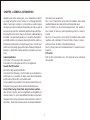
CHAPTER 1: GENERAL INFORMATION
Intelligent speed dome camera gives you a comprehensive view that
you simply can't get from a fixed camera. Our technology delivers the
details of your target, zooming in or out in less than a second to capture
the image you need. Zoom-Adjusted Programming (ZAP) lets you pan, tilt
and zoom in every direction, automatically adjusting the pan and tilt spe-
ed in proportion to the zoom so that you don't have to. Additional features
like Pattern, Group and Swing enable you to conduct a virtual patrol of
your facility whether or not someone is manning the controls. Auto-focus
with manual override renders a clear picture every time. From the most
distant corner of a parking garage to the maze of hallways throughout a
building, our speed dome cameras will take you everywhere you need
to see.
Camera Specification
CCD Sensor: 1/4" Sony Super HAD or Exview CCD
Zoom Ratio: 27X or 18X optical zoom 10X or 12X digital zoom
Powerful Pan/Tilt Functions
Max. 400/sec high speed Pan/Tilt Motion.
Using Vector Drive Technology, Pan/Tilt motions are accomplished in a
shortest path. As a result, time to target view is reduced dramatically
and the video on the monitor is very natural to watch.
For jog operation using a controller, since ultra slow speed 0.05/sec can
be reached, it is very easy to locate camera to desired target view.
Preset, Pattern, Swing, Privacy Mask, Group Functions and More
Max. 128 sets of position and zoom magnification are designated and
stored as Presets. For each Preset,additional information such as Dwell
time (pause time in Group action when camera reaches to a certain Pre-
set position), Alarm action and area Label can be assigned independen-
tly to meet to your requirements.
Max. 8 set of Swing action can be stored. This enables to move camera
repetitively between two preset positions with designated speed.
Max. 4 of Patterns can be recorded and played back. This enables to
move camera to follow any actions operated by joystick as closely as
possible.
Max. 8 set of Group action can be stored. This enables to move camera
repetitively with combination of Preset or Pattern or Swing. A Group is
composed of max. 20 entities of Preset/Pattern/Swings.
Max. 8 of Privacy masks can be located wherever it is required to protect
private life.
PTZ Control
With RS-485 communication, max. 255 of cameras can be controlled at
the same time
2

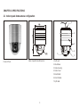
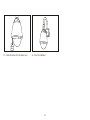
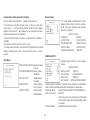
2.1 Indoor speed dome camera configuration
Product Photo
1
2
3
4
5
6
1. Rj45 Jack
2. Mount Base
3. Dome Housing
4. Dom Cover
5. Black Shield
6. Zoom Camera
7. Rj45 cable
e
Indoor Speed Dome Dimension
7
CHAPTER 2: SPECIFICATIONS
3

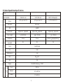
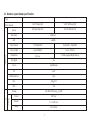
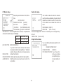
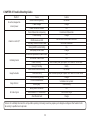
2.2 Indoor Speed Dome Specifications
Type
Zoom module
CNB 22X color
SONY 18X Day/night
1/4"Super Had CCD
1/4"IT EXVIEW CCD
1/4"Super Had CCD
Camera
Sensor
Resolution
S/N
Zoom Ratio
Focal Length
Illumination
Day/Night
Focus
Iris
White Balance
BLC
AGC
Optical 22X Digital10X
f 3.9-85.8mm
0.5Lux
No
Optical 18X Digital12X
f 4.1-73.8mm
0.7Lux
No
Optical 18X Digital 12X
f 4.1-73.8mm
0.002Lux Day/Night Mode
Yes
Auto/Manual
Auto
Auto
ON OFF
ON
480 Lines
48dB
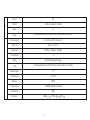
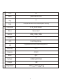
P/T
Speed
Range
Preset
Manual
Swing
oo
Pan 360 Continuous Tilt 90
o
400 /sec
oo
0.1 180 /sec
oo
15 60 /sec
SONY 18X color
4

P/T
128
4 Patterns and each 1 minute
8
8Groups and each with 20 action like preset,pattern and swing.
Preset
Pattern
Swing
Group
Communication
Protocol
Baud Rate
Privacy Mask
Alarm
OSD
Blower/Heater
Temperature
Moisture
RS-485 Max 255 Camera ID
Pelco-D Pelco-P
2400bps 4800bps 9600bps
8
8Input/4Output Optional
Programmable OSD for Pan/Tilt,Zoom Camer,Pattern etc. setting
No
oo
0 C+50 C
95%
Power Suplly
Consumption
Dimension
110-240VAC Input/12V DC Output
20W
215mm L 175mm W 235 H
5

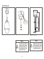
3.Outdoor Speed Dome configuration
Product Photo
Outdoor speed dome dimension
(with Sunshield)
Outdoor speed dome dimension
6

3.1 Outdoor speed dome specification
Type
Zoom moudle
Camera
Sensor
Resolution
S/N
Zoom module
Focal Length
Illumination
Day/Night
Focus
Iris
White Balance
BLC
AGC
Yes
Auto/Manual
Auto
Auto
ON OFF
ON
480Lines
48dB
P/T
Speed
Range
Preset
Manual
Swing
oo
Pan 360 Continuous Pan90
o
400 /sec
oo
0.1 180 /sec
oo
15 60 /sec
LG 27X Day/night
1/4"Super Had CCD
SONY 18X Day/night
1/4"IT EXVIEW CCD
27X Digital10X
f 3.25-88mm
0.01Lux
Optical18X Digital12X
f 4.1-73.8mm
0.002Lux Day/Night mode
7

P/T
128
4patterns and each 1 minute
8
8Groups and each with 20 actions,like preset,pattern and swing
Preset
Pattern
Swing
Group
Communication
Protocol
Baud Rate
Privacy Mask
Alarm
OSD
Blower/Heater
Temperature
Moisture
RS-485 Max 255 Camera ID
Pelco-D Pelco-P
2400bps 4800bps 9600bps
8
8Input/4Output Optional
Programmable OSD for Pan/Tilt, Zoom Camera,pattern etc .
Built in
oo
-35 C+50 C
95%
Power Supply
Consumption
Package Dimension
20W
215mm L 175mm W 235 H
110-240VAC Input/12V DC Output
8

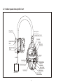
3.2 Outdoor speed dome profile Chart
Heater
Termostat
Blower
Termostat
Shield Mount
Tilt Motor
Black Shield
Zoom Module
Dome Cover
Pan Motor
Sunshield
Dome Housing
Bracket Mount
Base
Bracket Upper
Cover
Housing Upper Cover
Bracket Joint
Rs485
Alarm Box
Power Box
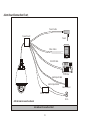
9

Monitor
Video
Controller
Alarm Input Cable
RS-485 Cable
Video Cable
Alarm Board connection Drawing
Siren
Alarm Sensor
220VAC/12VDC
Alarm Output Cable
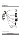
Alarm Board connection
10
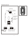
CHAPTER 3:Alarm Board connection
ACB
Power
ACB=Alarm & Connection Board

Monitor
Video
Controller
Power
RS-48 5Cable
Video Cable
Alarm Input Cable
Power Cable
Alarm Sensor
Alarm Board Connection Chart
Alarm Board Connection Chart
Siren
Alarm Output Cable
Power Board
220VAC 12VDC
11
ACB=Alarm & Connection Board

Alarm Board Connection (ACB)
NO NC
B A
O1 O2 O3 O4
A2A1 A3A4 G
B A
A6
A5
A7
A8
G
S1
S2
NC NO
120 Terminal Resistor
RS485
12V Power Input
Alarm Input 1-8
Alarm Output 1-4
G
1
2
3
4
Alarm Input 1-4
G
12VG
5 6 7 8
Alarm Input5-8
Alarm Output4
Alarm Output3
No.3Alarm Output Choice
NC off NO on
No.4 Alarm Output Choice
NC off NO on
ON
1
Alarm Output2
Alarm Output1
12

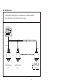
Rs485 Resistor
OFF
Rs485 Resistor
ON
#1
RS-485
Controller
#2
#N
OFF
Rs485 Resistor
.RS-485 Resistor
Jumper switch of terminal resistor is on the Alarm and Connection Board(ACB).
Just simply make it on "on" state for the last one camera.
13

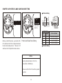
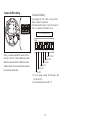
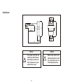
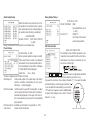
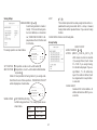
CHAPTER 4:PROTOCOL AND CAMERA ID SETTING
ONON
ID Dip
Protocol
Before you install the camera, you should set the
DIP switches on the PCB to configure the camera
ID and communication protocol. There are 2 DIP
switches on the PCB,positions shown as above.
ON
Protocol and Baud Rate Setting
Notice
Factory default protocol is PELCO-D
Baud Rate is 2400bits/sec,
Please confirm if the DIP reach the signated
position.
1 2 3 4 5 6
ON
ON
PRO0
PRO1
PRO2
ZM0
ZM1
NT/PAL
PRO0
PRO1
(Pin1)
(Pin2)
OFF
OFF
ON
OFF
OFF
ON
ON
ON
PELCO-D, 2400 bps
PELCO-D, 9600 bps
PELCO-P, 4800 bps
PELCO-P, 9600 bps
Protocol Setting
Protocol and
Baud Rate
Protocol Setting
1 2 3 4 5 6
ON
ON
PRO0
PRO1
PRO2
ZM0
ZM1
NT/PAL
Protocol/Baud
Switch State
14
Reserved

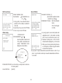
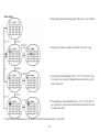
Camera ID DIP setting
Camera ID DIP
ON
When you want to operate the camera. The Ca-
mera ID in this DIP switch setting must be inde-
ntial to the camera ID of the controller.If you have
multiple cameras, it is recommended to memorize
the camera IDs and location
Camera ID Setting
By changing the DIP switch, you can set the
binary number for camera ID.
ON state of switch means '1' and OFF means '0'.
Ex) If you want to set camera ID as 10.
1 2 3 4 5 6 7 8
ON
32 (if 'ON')
16(if 'ON')
8(if 'ON')
4(if 'ON')
2(if 'ON')
1(if 'ON')
ID : 0+2+0+8+0=10
1. You can assign camera ID in the rage 1~255.
Do not use ID '0'.
2. Factory default of Camera ID is '1'.
15

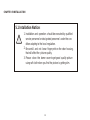
CHAPTER 5:INSTALLATION
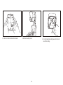
Installation and operation should be executed by qualified
service personnel or designated personnel under the con-
dition adapting to the local regulation.
Be careful and not leave finger print on the clear housing,
that will affect the picture quality.
Please clean the dome cover to get good quality picture
using soft cloth when you find the picture is getting dim.
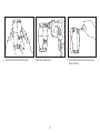
5.1 Intallation Notice:
1.
2.
3.
16

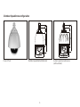
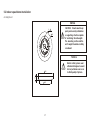
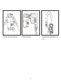
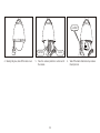
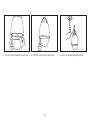
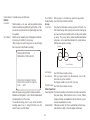
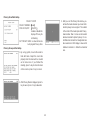
5.2 Indoor speed dome Installation
A.Ceiling Mount
109
30
180
140
22
5
127EQS
4 -
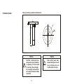
Notice
CAUTION: Mounts must be pr-
operly and securely installed on
a supporting structure capable
of sustaining the unit weight.
The mounting surface and the
unit's weight should be carefully
considered
Notice
Before install, please wear
attached white glove to avoid
blur or pull dome cover so as
to effect quality of picture.
17

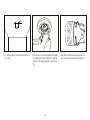
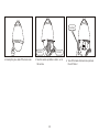
32
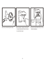
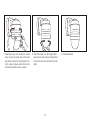
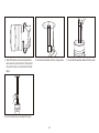
1. For cabling,make a hole sized ablout 32mm on
the celing.
2.If necessary, use a wood board to strengthen
the ceiling and fix the ceiling mount onto the
surface of the ceiling using the screws includ-
ed.
18
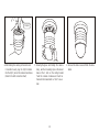
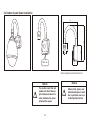
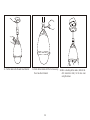
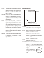
3. Take off the dome cover by turning anticlock-
wise and set up the camera ID and protocol.
Steel wire
Page is loading ...
Page is loading ...
Page is loading ...
Page is loading ...
Page is loading ...
Page is loading ...
Page is loading ...
Page is loading ...
Page is loading ...
Page is loading ...
Page is loading ...
Page is loading ...
Page is loading ...
Page is loading ...
Page is loading ...
Page is loading ...
Page is loading ...
Page is loading ...
Page is loading ...
Page is loading ...
Page is loading ...
Page is loading ...
Page is loading ...
Page is loading ...
Page is loading ...
Page is loading ...
Page is loading ...
Page is loading ...
Page is loading ...
Page is loading ...
Page is loading ...
Page is loading ...
Page is loading ...
Page is loading ...
-
 1
1
-
 2
2
-
 3
3
-
 4
4
-
 5
5
-
 6
6
-
 7
7
-
 8
8
-
 9
9
-
 10
10
-
 11
11
-
 12
12
-
 13
13
-
 14
14
-
 15
15
-
 16
16
-
 17
17
-
 18
18
-
 19
19
-
 20
20
-
 21
21
-
 22
22
-
 23
23
-
 24
24
-
 25
25
-
 26
26
-
 27
27
-
 28
28
-
 29
29
-
 30
30
-
 31
31
-
 32
32
-
 33
33
-
 34
34
-
 35
35
-
 36
36
-
 37
37
-
 38
38
-
 39
39
-
 40
40
-
 41
41
-
 42
42
-
 43
43
-
 44
44
-
 45
45
-
 46
46
-
 47
47
-
 48
48
-
 49
49
-
 50
50
-
 51
51
-
 52
52
-
 53
53
-
 54
54


Ask a question and I''ll find the answer in the document
Finding information in a document is now easier with AI
Related papers
Other documents
-
Sibell HDOB-AL2IR550ZW User manual
-
ICRealtime ICR-100X User manual
-
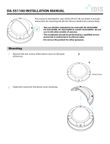 IDIS DA-SS1100 Technical Manual
-
Northern PTZWP12X Operating instructions
-
-
Mace MVC-PTZ-23X User manual
-
-
CNB SxB2xZ12F N User manual
-
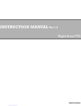 Rugged CCTV Night Scout TVI User manual
-
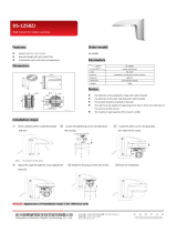 Kenuco DS-1258ZJ User guide


