Page is loading ...

1 - ENG
BEFORE OPERATING THIS TOOL, ALL OPERATORS SHOULD STUDY THIS MANUAL
TO UNDERSTAND AND FOLLOW THE SAFETY WARNINGS AND INSTRUCTIONS. KEEP
THESE INSTRUCTIONS WITH THE TOOL FOR FUTURE REFERENCE. IF YOU HAVE ANY
QUESTIONS, CONTACT YOUR STANLEY TOOLS REPRESENTATIVE OR DISTRIBUTOR.
ANTES DE OPERAR ESTA HERRAMIENTA, TODOS LOS OPERADORES DEBERÁN
ESTUDIAR ESTE MANUAL PARA PODER COMPRENDER Y SEGUIR LAS ADVERTENCIAS
SOBRE SEGURIDAD Y LAS INSTRUCCIONES. MANTENGA ESTAS INSTRUCCIONES
CON LA HERRAMIENTA PARA FUTURA REFERENCIA, SI TIENE ALGUNA DUDA,
COMUNÍQUESE CON SU REPRESENTANTE DE STANLEY TOOLS O CON SU
DISTRIBUIDOR.
LIRE ATTENTIVEMENT LE PRÉSENT MANUEL AVANT D’UTILISER L’APPAREIL. PRÉTER
UNE ATTENTION TOUTE PARTICULIÈRE AUX CONSIGNES DE SÉCURITÉ ET AUX
AVERTISSEMENTS. GARDER CE MANUEL AVEC L’OUTIL POUR FUTUR RÉFÉRENCE.
SI VOUS AVEZ DES QUESTIONS, CONTACTEZ VOTRE REPRÉSENTANT OU VOTRE
CONCESSIONNAIRE STANLEY TOOLS
9R197955RA 12/12
OPERATION AND MAINTENANCE MANUAL
MANUAL DE OPERACIÓN Y DE MANTENIMIENTO
MANUEL D’INSTRUCTIONS ET D’ENTRETIEN
FMFP12703
FRAMING NAILER
CLAVADORA PARA ESTRUCTURAS
CLOUEUSE DE CHARPENTE
2 - ENG
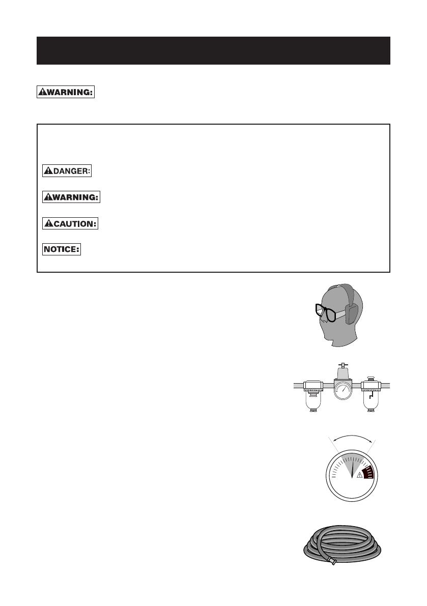
• Actuating tool may result in flying debris,
collation material, or dust which could harm
operator’s eyes. Operator and others in work
area MUST wear safety glasses with side
shields. These safety glasses must conform to
ANSI Z87.1 (CAN/CSA Z94.3) requirements (approved
glases have “Z87” printed or stamped on them). It is
the employer’s responsibility to enforce the use of eye
protection equipment by the tool operator and other
people in the work area. (Fig. A)
• Tominimizeflyingdustanddebrisrotateexhaust
deflectorawayfromyouandothersinthework
area.
• Always wear appropriate personal hearing
and other protection during use. Under some
conditionsanddurationofuse,noisefromthis
productmaycontributetohearingloss.(Fig. A)
• Useonlyclean,dry,regulatedair.Condensation
fromanaircompressorcanrustanddamagethe
internalworkingsofthetool.(Fig. B)
• Regulate air pressure. Use air pressure
compatiblewithratingsonthenameplateofthe
tool.[Not to exceed 120 psi (8.3 bar).] Do not connect
the tool to a compressor rated at over 200 psi. The tool
operating pressure must never exceed 200 psi even in
the event of regulator failure. (Fig. C)
Fig.B
Fig.A
Fig.D
IMPORTANTSAFETYINSTRUCTIONS
FORPNEUMATICTOOLS
SAVE THESE INSTRUCTIONS
When using any pneumatic tool, all safety precautions, as outlined
below, should be followed to avoid the risk of death or serious injury. Read and
understand all instructions before operating the tool.
DEFINITIONS-SAFETYGUIDELINES
The definitions below describe the level of severity for each signal word. Please read
the manual and pay attention to these symbols.
Indicates an imminently hazardous situation which, if not avoided,
willresult in deathorseriousinjury.
Indicates a potentially hazardous situation which, if not avoided,
could result in deathorseriousinjury.
Indicates a potentially haz ard ous situation which, if not avoided,
mayresult in minorormoderateinjury.
Used without the safety alert symbol indicates a situation which, if not
avoided,may result inpropertydamage.
120 psi
8.3 bar
Fig.C
3 - ENG
• Onlyuseanairhosethatisratedforamaximum
workingpressure ofatleast 150 psi(10.3 bar)
or 150% of the maximum system pressure,
whicheverisgreater.(Fig. D)
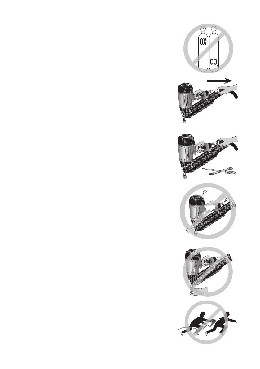
• Do not use bottled gases to power this tool.
Bottledcompressedgasessuchasoxygen,carbon
dioxide,nitrogen,hydrogen,propane,acetylene
or air are not for use with pneumatic tools.
Never use combustible gases or any other reactive gas
as a power source for this tool. Danger of explosion
and/or serious personal injury may result. (Fig. E)
• Use couplings that relieves all pressure from
the tool when it is disconnected from the
power supply. Use hose connectors that shut
offairsupplyfromcompressorwhenthetoolis
disconnected.(Fig. F)
• Disconnect tool from air supply when not in
use. Always disconnect tool from air supply
and remove fasteners from magazine before
leavingtheareaorpassingthetooltoanother
operator.Donotcarrytooltoanotherworkarea
inwhich changing locationinvolvesthe useof
scaffoldings,stairs,ladders, and thelike, with
airsupplyconnected.Donotmakeadjustments,
removemagazine,performmaintenanceorclear
jammed fasteners while connected to the air
supply. If the contact trip is adjusted when the tool
is connected to the air supply and nails are loaded,
accidental discharge may occur. (Fig. G)
• Connect tool to air supply before loading
fasteners to prevent an unintentional fastener
discharge during connection.The tool driving
mechanismmaycyclewhenthetoolisconnected
to the air supply. Never load fasteners with the
trigger or the contact trip depressed to prevent
unintentional driving and possibly causing injury.
• Donotremove,tamperwith,orotherwisecause
the tool, trigger, or contact trip to become
inoperable.Donottapeortietriggerorcontact
tripintheonposition.Do not remove spring from
contact trip. Make daily inspections for free movement
of trigger and contact trip. Uncontrolled discharge
could result possibly causing injury.
• Inspect tool beforeuse.Do not operate a tool
if any portion of the tool, trigger, or contact
tripisinoperable,disconnected,altered,ornot
working properly. Leaking air, damaged parts or
missing parts should be repaired or replaced before
use. Refer to Repairs. (Fig. H)
• Donotalterormodifythetoolinanyway.(Fig.I)
• Alwaysassumethatthetoolcontainsfasteners.
Fig.E
Fig.F
Fig.I
Fig.J
Fig.G
Fig.H

4 - ENG
• Donotpointthetoolatco-workersoryourself
atanytime.Nohorseplay!Work safe! Respect the
tool as a working implement. (Fig. J)
• Keep bystanders, children, and visitors away
while operating a power tool. Distractions can
causeyoutolosecontrol.When tool is not in use,
it should be locked in a safe place, out of the reach of
children.
• Remove finger from trigger when not driving
fasteners.
• Never carry tool with finger on trigger. Using
the trigger lock-off will prevent accidental
discharge.Accidental discharge could result.
• Do not overreach.Maintain proper footingand
balance at all times. Loss of balance may cause
personal injury. (Fig. K)
• Makesurehoseisfreeofobstructionsorsnags.
Entangled or snarled hoses can cause loss of
balanceorfooting.
• Use the tool only for its intended use. Do not
discharge fasteners into open air, concrete,
stone, extremely hard woods, knots or any
materialtoohardforthefastenertopenetrate.
Do not use the body of the tool or top cap as a
hammer. Discharged fasteners may follow unexpected
path and cause injury. (Fig. L)
• Always keep fingers clear of contact trip to
preventinjuryfrominadvertentreleaseofnails.
(Fig.M)
• Referto the Maintenanceand Repairs sections
for detailed information on the proper mainte-
nanceofthetool.
• Alwaysoperatethetoolinaclean,lightedarea.
Besuretheworksurfaceisclearofanydebris
andbecarefulnottolosefootingwhenworking
inelevatedenvironmentssuchasrooftops.
• Do not drive fasteners near edge of material.
Theworkpiecemaysplitcausingthefastenerto
ricochet, injuring you or a co-worker. Be aware
that the nail may follow the grain of the wood (shiner),
causing it to protrude unexpectedly from the side of
the work material. Drive the nail perpendicular to the
grain to reduce risk of injury. (Fig. N)
• Do not drive nails onto the heads of other
fastenersorwiththetoolattoosteepanangle.
Personal injury from strong recoil, jammed
fasteners,orricochetednailsmayresult.(Fig. O)
• Beawareofmaterialthicknesswhenusingthe
nailer.Aprotrudingnailmaycauseinjury.
Fig.K
Fig.L
Fig.M
Fig.N
Fig.O

5 - ENG
• Be aware that when the tool is being utilized
at pressures on the high end of its operating
range, nails can be driven completely through
thinorverysoftworkmaterial.Makesurethe
pressureinthecompressorissetsothatnails
are set into the material and not pushed com-
pletelythrough.(Fig. P)
• Keephandsandbodypartsclearofimmediate
work area. Hold workpiece with clamps when
necessarytokeephandsandbodyoutofpotential
harm. Be sure the workpiece is properly secured
before pressing the nailer against the material. The
contact trip may cause the work material to shift
unexpectedly. (Fig. Q)
• Do not use tool in the presence of flammable
dust,gasesorfumes.Thetoolproducessparks
thatcouldignitecausingafire.Driving a nail into
another nail may also cause a spark. (Fig. R)
• Keep face and body parts away from back of
thetoolcapwhen workinginrestricted areas.
Suddenrecoilcanresultinimpacttothebody,
especially when nailing into hard or dense
material.(Fig. S)
• Grip tool firmly to maintain control while
allowingtooltorecoilawayfromworksurface
as fastener is driven. In bump action mode
(contact actuation mode) if contact trip is
allowed to recontact work surface before
triggerisreleasedanunwantedfastenerwillbe
driven.
• Choiceoftriggeringmethodisimportant.Check
themanualfortriggeringoptions.
BUMPORCONTACTACTUATIONTRIGGER(RED)
• Whenusingthebumpactiontrigger,becareful
of unintentional double fires resulting from
toolrecoil.Unwantedfastenersmaybedriven
if the contact trip is allowed to accidentally
re-contacttheworksurface,whilethetrigger
is still being held in the actuated position.
(Fig. T)
TOAVOIDDOUBLEFIRES:
• Donotengagethetoolagainsttheworksurface
with a strong force.
• Allowthetooltorecoilfullyaftereachactuation.
• Usesequentialactiontrigger.
• Whenbumpactuatingthenailer,alwayskeep
toolin control.
Inaccurateplacement of tool
can result in misdirected discharge of a
fastenerpossiblycausinginjury.
Fig.Q
Fig.R
Fig.S
Fig.P
Fig.T
FIG.U

6 - ENG
SEQUENTIALACTIONTRIGGER(GREY)
• When using the sequentialaction trigger, do not actuate the tool
unlessthetoolisplacedfirmlyagainsttheworkpiece.
• DEPTHADJUSTMENT:Toreduceriskofseriousinjuryfromaccidental
actuationwhenattemptingtoadjustdepth,ALWAYS:
• Disconnectairsupply.
• Avoidcontactwithtriggerduringadjustments.
• Do not drive nails blindly into walls, floors or other work areas.
Fastenersdrivenintoliveelectricalwires,plumbing,orothertypesof
obstructionscanresultininjury.(Fig. U)
• Stayalert, watch what you are doing and use common sense when
operating a power tool. Do not use tool while tired or under the
influence of drugs or alcohol. A moment of inattention while operating
power tools may result in serious personal injury.
Some dust created by power sanding, sawing, grinding, drilling, and
other construction activities contains chemicals known to the State of California to
cause cancer, birth defects or other reproductive harm. Some examples of these
chemicals are:
• lead from lead-based paints
• crystalline silica from bricks and cement and other masonry products
• arsenic and chromium from chemically-treated lumber
Your risk from these exposures varies, depending on how often you do this type
of work. To reduce your exposure to these chemicals: work in a well ventilated
area, and work with approved safety equipment, such as those dust masks that
are specially designed to filter out microscopic particles.
Use of this tool can generate and/or disburse dust, which may cause
serious and permanent respiratory or other injury. Always use NIOSH/OSHA
approved respiratory protection appropriate for the dust exposure. Direct particles
away from face and body. Always operate tool in well-ventilated area and provide
for proper dust removal. Use dust collection system wherever possible.
ALWAYS USE SAFETY GLASSES. Everyday eyeglasses are NOT
safety glasses. Also use face or dust mask if operation is dusty. ALWAYS WEAR
CERTIFIED SAFETY EQUIPMENT:
• ANSIZ87.1eyeprotection(CAN/CSAZ94.3),
• ANSIS12.6(S3.19)hearingprotection,
• NIOSH/OSHArespiratoryprotection.
Before operating this tool, carefully read and understand all instructions
in Important Safety Instructions.
NAILSPECIFICATIONS
FMFP12703
Nails 0.113" – 0.131" (2.87–3.33 mm) diameter,
papertape collated clipped head framing nails
Lengths 2"–3-1/2" (50–90 mm)
Angle 34º
AirInlet 1/4"NPT(6.4mm)

7 - ENG
TOOLPARTS
Fig.1
A. Exhaust deflector
B. Trigger (contact or sequential)
C. Air Inlet with quick
connect coupler
D. Magazine
E. Nail stop
F. Contact trip with No-mar pad
G. Depth adjustment wheel
H. Pusher
I. Pusher release
ASSEMBLY
Disconnect air line from tool and remove fasteners from
magazinebeforemakingadjustmentsorpersonalinjurymayresult.
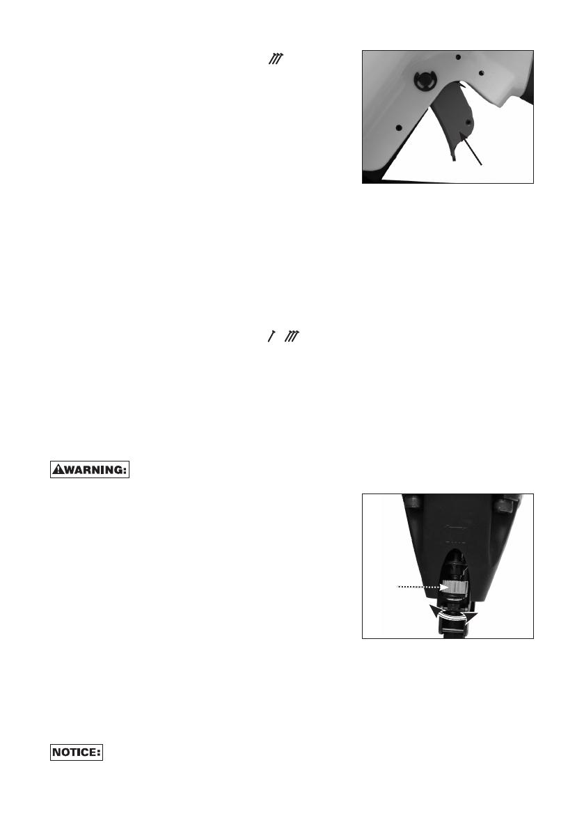
TRIGGER
Keep fingers AWAY from the trigger when not driving fasteners to
avoid accidental actuation. Never carry a tool with your finger on the trigger. In
bump action mode (contact actuation mode), the tool will drive a fastener if the
contact trip is bumped while the trigger is depressed.
SEQUENTIALTRIP(Graytrigger):
The Sequential Trip requires the operator to hold the tool against the work surface
before pulling the trigger. This makes accurate fastener placement easier, for
instance on framing, toe nailing and crating applications.The Sequential Trip
allows exact fastener placement without the possibility of driving a second
fastener on recoil, as described under “Contact Trip”. The Sequential Trip Tool has a
positive safety advantage because it will not accidentally drive a second fastener
if the tool is contacted against the work – or anything else – while the operator is
holding the trigger pulled.
CONTACTTRIP(Redtrigger):
The common operating procedure on “Contact Trip” tools is for the operator to
contact the work surface to actuate the trip mechanism while keeping the trigger
pulled, thus driving a fastener each time the work is contacted. This will allow
rapid fastener placement on many jobs, such as sheathing, decking and pallet
assembly. All pneumatic tools are subject to recoil when driving fasteners. The
tool may bounce, releasing the trip, and if unintentionally allowed to re-contact
the work surface with the trigger still actuated (finger still holding trigger pulled)
an unwanted second fastener will be driven.
A
C
B
EDH I
G
F

8 - ENG
AIRFITTING
A3/8"(9.5mm)malequickconnectorcouplingmaybeusedwhena1/4"(6.4mm)
supply line is not available.
Always use couplings that relieve all pressure from the tool when it
is disconnected from the power supply. Always use hose connectors that shut off
air supply from compressor when the tool is disconnected.
Toinstallanairfitting
1. Wrap the male end of the fitting with thread seal tape prior to assembly to
eliminate air leaks.
2. Toinstalla1/4"(6.4mm)fitting:screwitdirectlyintotheairinletandtighten
firmly. NOTE: If an adapter is in the air inlet, remove it prior to inserting the
fitting.
3. To install a 3/8" (9.5 mm) fitting: screw the fitting into the 3/8" (9.5 mm) adapter
and then into the air inlet of the tool and tighten firmly.
OPERATION
PREPARINGTHETOOL
Read the section titled Important Safety Instructions for
PneumaticTools at the beginning of this manual. Always wear eye and ear
protection when operating this tool. Keep the nailer pointed away from yourself
and others. For safe operation, complete the following procedures and checks
before each use of the nailer.
To reduce the risk of damage to the tool, only use a non-detergent SAE
20 weight oil.
1. Before you use the nailer, be sure that the compressor tanks have been
properly drained.
2. Lubricate tool:
a. To reduce the risk of damage to the tool, only use a non-detergent SAE 20
weight oil
b. Use a filter when possible.
c. Add 5 to 7 drops of oil in the air fitting a least twice a day.
3. Always wear eye and ear protection.
4. Ensure magazine is empty of all fasteners.
5. Check for smooth and proper operation of contact trip. Do not use tool if
assembly is not functioning properly. NEVER tamper with the contact trip.
NEVER use a tool that has the contact trip restrained in the actuated position.
6. Check air supply: Ensure air pressure does not exceed recommended
operating limits; 70 to 120 psi, (4.9 to 8.3 bar, 5 to 8.5 kg/cm
2
).
7. Keep tool pointed away from yourself and others.
8. Connect air hose.
9. Check for audible leaks around valves and gaskets. Never use a tool that leaks
or has damaged parts.
Toreducetheriskofpersonalinjury,alwaysdisconnecttool
from air supply before performing maintenance, clearing a jammed
fastener,leavingworkarea,movingtooltoanotherlocationorhanding
thetooltoanotherperson.

9 - ENG
LOADINGTHETOOL(FIG.1–4)
Keep the tool pointed away from
yourself and others. Serious personal injury may
result.
Never load nails with the contact trip
or trigger activated. Personal injury may result.
1. Read all SafetyWarnings before using tool.
2. Connect the air supply to the tool.
3. Insert fasteners (L) into T-slot (K) on end cap
of magazine (J) past the nail stop (E). NOTE:
Magazine will hold two full fastener strips.
4. Pull pusher (I) back until the nail stop (E) falls behind the fasteners.
NOTE: Do not allow the pusher to snap forward against the nail strip, allowing this
to happen could damage the nail collation.
ACTUATINGTOOL
To reduce the risk of injury, ALWAYS wear proper eye ANSI Z87.1
(CAN/CSAZ94.3)andhearingprotectionANSIS12.6(S3.19)whenoperatingthis
tool. The tool can be actuated using one of two modes: single sequential actuation
trigger mode and contact actuation trigger mode.
Sequentialactuationtrigger(gray)- (Fig.5)
Allow the tool to recoil off the work surface after actuation. If the
contact trip remains depressed a nail will be driven each time the trigger is
released and pulled, which could result in accidental actuation, possibly causing
injury.
The sequential actuation trigger’s intended use is
for intermittent fastening where accurate fastener
placement is desired.
To operate the tool in sequential actuation
mode:
1. Depress the contact trip firmly against the
work surface.
2. Pull the trigger.
3. Allow the tool to recoil from the work surface.
Fig.3
L E
Fig.4
H
I
L
Fig.2
E
J
K
L
Fig.5
Gray-sequential
10 - ENG
Contactactuationtrigger(red)- (Fig.6)
The contact actuation trigger is intended for rapid
fastening on flat, stationary surfaces.
Using the contact actuation trigger, two methods
are possible: place actuation and contact
actuation.
TooperatethetoolusingthePLACE
ACTUATIONmethod:
1. Depress the contact trip against the work
surface.
2. Pull the trigger to drive the fastener.
3. Allow the tool to recoil off the work surface and release the trigger after each
actuation.
TooperatethetoolusingtheCONTACTACTUATIONmethod:
1. Pull the trigger.
2. Depress the contact trip against the work surface. As long as the trigger is
pulled, the tool will drive a fastener every time the contact trip is depressed.
This allows the user to rapidly drive multiple fastener in sequence.
ChangingtheActuationMode-
1. Remove E-Ring
2. Remove the trigger pin and trigger
3. Select the appropriate trigger based on your needs and trigger operation
modes
4. Install the trigger and install the trigger pin
5. Test nailer and verify function
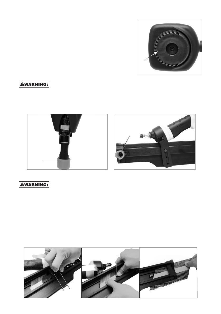
ADJUSTINGDEPTH(FIG.7)
To reduce risk of serious injury from accidental actuation when
attempting to adjust depth, ALWAYS:
• Disconnectairsupply.
• Avoid contact with trigger during
adjustments.
The depth that the fastener is driven can be
adjusted using the depth adjustment wheel (G).
The depth of drive is factory adjusted. Test
drive a fastener and check depth. If a change is
desired:
1. To drive the nail shallower, rotate the depth
setting wheel (G) to the left.
2. To drive a nail deeper, rotate the depth setting wheel (G) to the right.
The adjustment knob has detents every full turn. Test drive another fastener and
check depth. Repeat as necessary to achieve desired results. The amount of air
pressure required will vary depending on the size of the fastener and the material
being fastened. Experiment with the air pressure setting to determine the lowest
setting that will consistently perform the job at hand.
Air pressure in excess of that required can cause premature wear and/or
damage to the tool.
Fig.7
G
Fig.6
Red-Contact
11 - ENG
DIRECTIONALEXHAUSTDEFLECTOR
(FIG.8)
Adjust directional exhaust deflector (A), so the
exhaust air blast will be directed away from the
operator. The exhaust deflector provides twelve
detented positions for directing the exhaust blast
away from the operator. Grasp the deflector and
rotate it to the desired position for the current
application.
NO-MARPAD(FIG.9,10)
Disconnect tool from air supply before removing or re-installing
no-mar pad.
The no-mar pad (F) is provided to reduce marring of the work surface. The no-mar
pad can be removed, and stored on the End Cap, Magazine (M), to provide increased
depth-of-drive for toe-nailing applications.
CLEARINGAJAMMEDNAIL(FIG.1,11–13)
Alwaysdisconnectairlinefromtoolandremovefasteners
frommagazinebeforemakingadjustmentsorpersonalinjurymayresult.
If a nail becomes jammed in the nosepiece, keep the tool pointed away from you
and follow these instructions to clear:
1. Disconnect the air supply from the tool.
2. Depress pusher release (I) and slide pusher (H) all the way to the front of the
magazine.
3. Depress nail stop (E) and slide fasteners from magazine.
4. If nail is jammed between the driver and nose casting force driver blade back
tothetopusinga1/4"(6.4mm)punchandhammer.Whenthenailisreleased
it will fall free or can be removed using pliers.
Fig.9
F
Fig.10
M
Fig.11
I
H
E
Fig.8
A

12 - ENG
5. If nail still can not be removed,
remove the magazine:
a. Remove screws (N).
b. Remove magazine.
c. Remove bent nail.
d. Reassemble in reverse order.
6. Verifyfunction.
NOTE: Should nails continue to jam
frequently in nosepiece, have tool
serviced by an authorized Stanley Black
and Decker service center.
COLDWEATHEROPERATION
When operating tools at temperatures below freezing:
1. Make sure compressor tanks have been properly drained prior to use.
2. Keep tool as warm as possible prior to use.
3. Make certain all fasteners have been removed from magazine.
4. Put 5 to 7 drops of non-detergent SAE 20 weight pneumatic tool oil in the air
inlet.
5. Lower air pressure to 80 psi (5.5 bar) or less.
6. Reconnectairandloadnailsintomagazine.
7. Actuatethetool5or6timesintoscraplumbertolubricateO-rings.
8. Turn pressure up to operating level (not to exceed 120 psi) and use tool as
normal.
9. Re-lubricate at least once daily.
10. Always drain the compressor tanks daily or after each use.
HOTWEATHEROPERATION
Tool should operate normally. However, keep tool out of direct sunlight as
excessive heat can deteriorate bumpers, O-rings and other rubber parts resulting
in increased maintenance.
Fig.12
Fig.13
N
N

13 - ENG
MAINTENANCE
Alwaysdisconnectairlinefromtoolandremovefasteners
frommagazinebeforemakingadjustmentsorpersonalinjurymayresult.
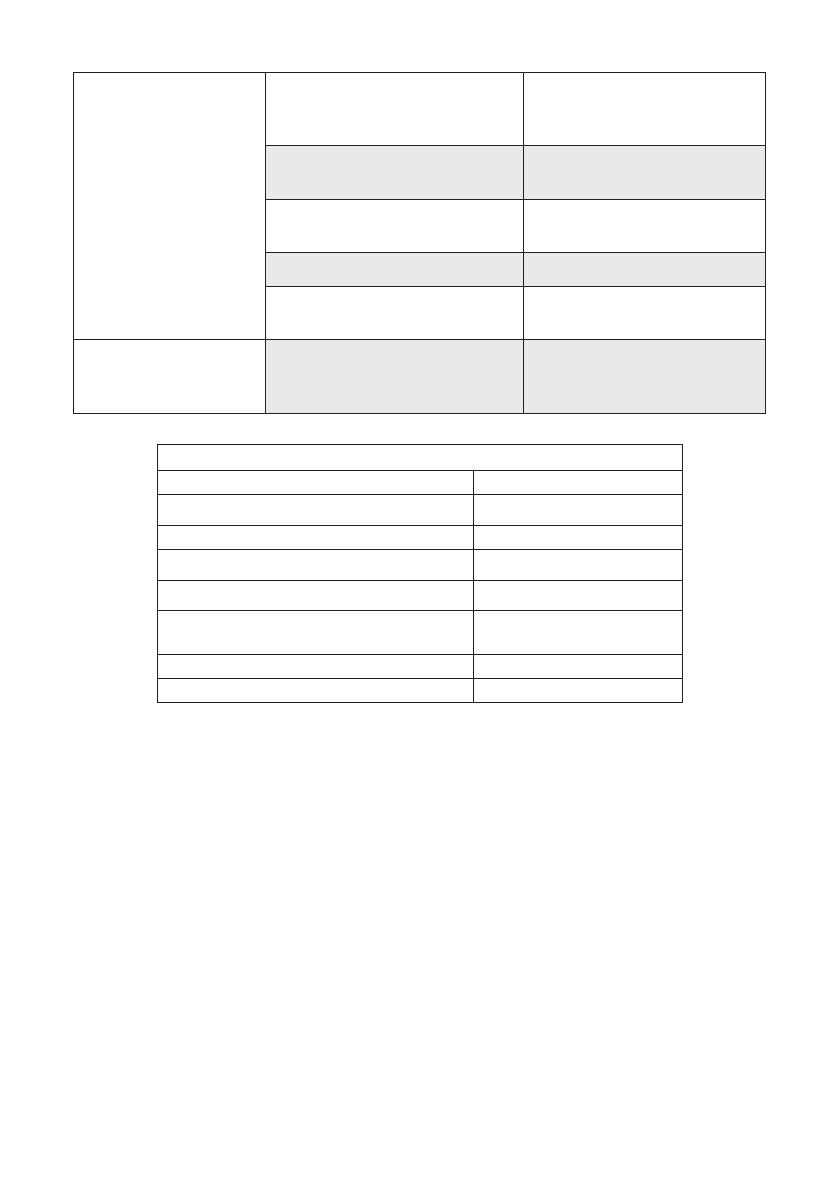
DAILYMAINTENANCECHART
ACTION WHY HOW
Lubricate tool with
5-7 drops of
non-detergent SAE 20
weight pneumatic tool oil.
Prevents failure
of o-rings.
Insert drops into air fitting
on end cap of tool.
Drain compressor
tanks and hoses daily
or after each use.
Prevents
accumulation
of moisture in
compressor
and nailer.
Open petcocks or other drain
valves on compressor tanks.
Allow any accumulated
water to drain from hoses.
Clean magazine,
magazine release and
contact trip mechanism.
Permits smooth
operation of
magazine,
reduces wear and
prevents jams.
Blow clean with compressor
air. The use of oils, lubricants
periodically or solvents is
not recommended as they
tend to attract debris.
Before each use, check
to insure all screws,
nuts and fasteners are
tight and undamaged.
Prevents jams, leaks
and premature
failure of tool parts.
Tighten loose screws
or other fasteners using
the appropriate hex
wrench or screwdriver.
CLEANING
Never use solvents or other harsh chemicals for cleaning the non-
metallic parts of the tool. These chemicals may weaken the materials used in these
parts. Use a cloth dampened only with water and mild soap. Never let any liquid
get inside the tool; never immerse any part of the tool into a liquid.
SERVICE
REPLACEMENTPARTS
Use only identical replacement parts. Refer to your Parts List for replacement part
numbers. You can order parts from your nearest Stanley Black & Decker Factory
Service Center or Authorized Warranty Service Center. Or, you can call our Customer
Care Center at 1-888-848-5175 (U.S. & Canada Only).
SERVICEANDREPAIRS
All quality tools will eventually require servicing and/or replacement of parts. For
information about Stanley Black & Decker Factory Service Center or Authorized
Warranty Service Centers call our Customer Care Center at 1-888-848-5175 (U.S.
& Canada Only). All repairs made by our service centers are fully guaranteed
against defective material and workmanship. We cannot guarantee repairs made or
attempted by others.

14 - ENG
THREEYEARLIMITEDWARRANTY
STANLEY TOOLS ("STANLEY") warrants to the original retail purchaser that this
product is free from defects in material and workmanship, and agrees to repair or
replace, at STANLEY option, any defective product within 3 year from the date of
purchase. This warranty is not transferable. It only covers damage resulting from
defects in material or workmanship, and it does not cover conditions or malfunctions
resulting from normal wear, neglect, abuse, accident or repairs attempted or made
by other than our regional repair center or authorized warranty service center.
Driver blades, bumpers and o-rings are considered normally wearing parts.
THIS WARRANTY IS IN LIEU OF ALL OTHER EXPRESS WARRANTIES. ANY
WARRANTY OF MERCHANTABILITY OR FITNESS FOR A PARTICULAR PURPOSE IS
LIMITED TO THE DURATION OF THIS WARRANTY. STANLEY SHALL NOT BE LIABLE
FOR ANY INCIDENTAL OR CONSEQUENTIAL DAMAGES.
This warranty is limited to sales in the United States and Canada. Some states
do not allow limitations on how long an implied warranty lasts, or the exclusion
or limitation of incidental or consequential damages, so the above limitations or
exclusions may not apply to you. This warranty gives you specific legal rights, and
you may also have other rights which vary from state to state.
To obtain warranty service, return the product at your expense together with proof
of purchase to a STANLEY regional or authorized warranty repair center. You may
also contact us at 1-888-848-5175 for the location of authorized warranty service
centers in your area.
TROUBLESHOOTINGGUIDE
MANYCOMMON PROBLEMS CAN BE SOLVED EASILY BY UTILIZINGTHECHART
BELOW. FOR MORE SERIOUS OR PERSISTENT PROBLEMS, CONTACT A STANLEY
BLACK&DECKERSERVICECENTERORCALL1-888-848-5175.
To reduce the risk of serious personal injury, ALWAYS
disconnectairfromtoolbeforeallrepairs.
SYMPTOM PROBLEMS SOLUTIONS
Air leak near
top of tool or in
trigger area
Loose screws. Tighten screws.
Worn or damaged
o-rings or seals.
Install Overhaul Kit.
Tool does nothing or
operates sluggishly
Inadequate air supply. Verifyadequateairsupply.
Inadequate lubrication. Put 5 or 7 drops of
oil into air inlet.
Worn or damaged
o-rings or seals.
Install Overhaul Kit.
Air leak near
bottom of tool
Loose screws. Tighten screws.
Worn or damaged
o-rings or bumper.
Install Overhaul Kit.
15 - ENG
Tool jams frequently Incorrect fasteners. Verifyapprovedfasteners
of correct size and
34° collation angle.
Damaged fasteners.
Bent collation wire.
Replace with
undamaged fasteners.
Canister or nose
screws loose
Tighten screws.
Canister is dirty. Clean magazine.
Driver tip is worn
or damaged.
Install Driver
Maintenance Kit.
Other Contact a STANLEY
Authorized Warranty
Service Center
TOOLSPECIFICATIONS
FMFP12703
Height (inch/mm) 15 / 381
Width (inch/mm) 4.5 / 114.3
Length (inch/mm) 17.5 / 444.5
Weight (lbs/kg) 7.47 / 3.39
Recommended
OperatingPressure
70-120 psi (4.8 to 8.3 bar)
AirConsumptionper100cycles
9.74 CFM
Loadingcapacity 80 nails

16 - ENG
Compressorwillbesufficientfortoolsatallproductionrates.
Compressorwillbesufficientatslowormoderateproduction
rates,butmayhavedifficultyatveryrapidrates.
Compressor will be adequate only when tools are utilized at
slowproductionrates(punch-outoroccasionaluse).
NR
NotRecommended
Portable
Handcarry
3.2 – 4 CFM
5.5 HP Gas
2 HP Elec.
8 – 9 CFM
8 HP Gas
14 – 16 CFM
Industrial
23+ CFM
NUMBEROFTOOLSCONNECTEDTOCOMPRESSOR
1
2
3
4
NR
5
NR
6
NR NR
7
NR NR
8+
NR NR
/