Schwaiger LWH 031 User manual
- Category
- Flat panel wall mounts
- Type
- User manual
Page is loading ...
Page is loading ...
Page is loading ...
Page is loading ...
Page is loading ...
Page is loading ...

7
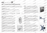
4. Technische Daten
9 cm (3.54“)
16,5 cm (6.5“)
20,1 cm (7.9“)
+/- 20°
+/- 90°
Kabel / Cable
+/- 90°

8
COMPANY INFORMATION
Dear customer,
In case you will need further technical support and your dealer is not available please contact our
help line:
Schwaiger GmbH
Würzburger Straße 17
90579 Langenzenn
Hotline: +49 (0) 9101 702-299
www.schwaiger.de
info@schwaiger.de
Opening hours
Monday to Thursday: 08:00-17:00 h
Friday: 08:00-14:30 h
Content
COMPANYINFORMATION ......................................................10
WARNING ...................................................................12
Safety Notes .................................................................12
Hardware kit .................................................................13
ToolsRequired. . . . . . . . . . . . . . . . . . . . . . . . . . . . . . . . . . . . . . . . . . . . . . . . . . . . . . . . . . . . . . . .13
1.MountingtheWallPlate .......................................................14
1.1 Wood Stud Installation .......................................................14
1.2 Concrete/Brick Installation ....................................................14
2. Attaching the Arm to the LCD ..................................................15
3. Final Installation and Operation .................................................16
3.1 Final Installation. . . . . . . . . . . . . . . . . . . . . . . . . . . . . . . . . . . . . . . . . . . . . . . . . . . . . . . . . . . .16
3.2OperationandAdjustment ....................................................16
4. Technical Data ..............................................................17

9
Tools Required
PhillipsHeadScrewdriver
Studnderfordrywallinstallation
Electric drill and 1/4” (8mm) masonry bit for concrete/brick installation
Note: You need to insert the bubble level system when you install the wall plate and take it
away fate you nish installation.
WARNING
• Donotbegintheinstallationuntilyouhavereadandunderstoodtheinstructionsandwarnings
containedinthisinstallationsheet.Ifyouhaveanyquestionregardinganyoftheinstructionsor
warnings, please contact your local distributor.
• ThismountingbracketwasdesignedtobeinstalledandutilisedONLYasspeciedinthismanual.
Improperinstallationofthisproductmaycausedamageorseriousinjury.
• Thisproductshouldonlybeinstalledbysomeonewith good mechanical ability who has basic
buildingexperienceandfullyunderstandsthismanual.
• Makesurethatthesupportingsurfacewillsafelysupportthecombinedweightoftheequipment
and all attached hardware and components.
• Alwaysuseanassistantormechanicalliftingequipmenttosafelyliftandpositiontheequipment.
• Tightenscrewsrmly,butdonotovertighten.Overtighteningcancausedamagetotheitems,This
greatly reduces their holding power.
• Thisproductisintendedforindooruseonly.Usingthisproductoutdoorscouldleadtoproduct
failureandpersonalinjury.
Safety Notes
Ifyouhavedoubtsaboutasafeinstallation,haveitinstalledbyaqualiedtechnician.
SCHWAIGERcannotbeheldresponsiblefordamageorinjurycausedbyimproperinstallationor
improper use.
Note: The included mounting hardware is only suitable for solid wall/ceiling construction. If you are
notsureoftheconditionoftheexistingwall/ceilinginmind,consultaspecialist.Theincludedhard-
ware is not suitable for steel.

10
Hardware kit
50 mm (2x)
Wood Screw
A
Bubble Level System
E
S = 5 mm
Allen Wrench
F
M4 x 12 mm (4x)
Head Screw
B
M4 x 30 mm (4x)
Head Srew
C
16 mm (4x)
Spacer
D
IMPORTANT:
Ensure that you have received all parts according to the component checklist prior to instal-
lation. If any parts are missing or faulty, telephone your local distributor for a replacement.
1. Mounting the Wall Plate
1.1 Wood Stud Installation
1.Place the wall plate against the wall with the hook
towards the bottom.
2. Secure the wall plate using one 2” wood screw (A).
3.Using the bubble level system (E), carefully adjust the
wall plate until it is level.
4. Attach the remaining 2” wood screw into the wall plate
and tighten.
Note: Using a wood stud nder, locate the stud centers
behind the wall. Once found, make a pencil marking on
the center of the wood studs.
Once the mark is made, it is strongly recommended that
a pilot hole be drilled with a 1/8” drill bit.

11
1.2 Concrete/Brick Installation
Note
1/4”(8mm) anchor must be used for concrete instal-
lation. They can be purchased at your local hardware
store.
1.Place the wall plate against the wall with the hook
towards the bottom.
2 Level and mark with a pencil the two mounting points
found on the wall plate.
3.Next, drill two holes using an electric drill and 1/4”
masonry bit.
4. Insert the threshold anchors into the holes that were
drilled in the wall.
Note: If necessary, use a hammer to lightly tap each anchor into place so that they are ush
with the wall.
5. Once the anchors are in place, put the wall piece back over the concrete anchors.
6. Using a screw driver, attach the back plate by threading the two screws into the anchor which has
been recessed into the wall.
7. Make sure all screws are snug, but be careful not to over-tighten them.
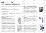
2. Attaching the Arm to the LCD
1. Determine the mounting hardware that is to be used.
2.IfyourLCDhasaatback,usetheM4x12mmHeadScrews(B).
Note: If your LCD has a recessed back, use
the longer M4x30mm Phillips Head Screws (C)
and 3/4” spacers (D).
3. After you have determined the ap-
propriate screws, use them
to attach the mounting plate to the back of your
LCD
4. Do not over-tighten the screws.

12
3. Final Installation and Operation
3.1 Final Installation
1. To complete the installation, simply slide the arm piece onto
the wall plate.
2. The plastic tab on the top of the wall piece should click, indi-
cating that the arm piece is secure.
3. If you need to remove the arm piece, push in on the tab and
slide the arm up.
4. For additional security and stability, tighten the security bolt
located on base of the arm piece using the Allen Wrench (F)
included in the hardware kit.
3.2 Operation and Adjustment
Note: Adjustment of your LCD may vary by model
On most models, the tilt angle of your LCD can be
adjustedbyrstlooseningthegearjointthatholds
the tilt in place. To do this, locate the adjustment
knob directly behind the LCD mounting point.
Loosen it by turning the knob counter-clockwise.
Adjustthetilttothedesiredlevelandre-tightenthe
knob. Other viewing adjustments can be made by
simple moving the arm into the desired position. If
youndthatajointistoodifculttomoveordoes
notholdtheLCDinplace,youcanadjustthetight-
ness of the joint. If your mount includes black ad-
justmentknobs,turnaknobclockwisetotightenand
counter-clockwise to loosen. If your mount does not
have knobs, use the Allen Wrench (F) to tighten or
loosenthejoint.

13
4. Technical Data
9 cm (3.54“)
16,5 cm (6.5“)
20,1 cm (7.9“)
+/- 20°
+/- 90°
Kabel / Cable
+/- 90°
Page is loading ...
Page is loading ...
Page is loading ...
-
 1
1
-
 2
2
-
 3
3
-
 4
4
-
 5
5
-
 6
6
-
 7
7
-
 8
8
-
 9
9
-
 10
10
-
 11
11
-
 12
12
-
 13
13
-
 14
14
-
 15
15
-
 16
16


Schwaiger LWH 031 User manual
- Category
- Flat panel wall mounts
- Type
- User manual
Ask a question and I''ll find the answer in the document
Finding information in a document is now easier with AI
in other languages
- Deutsch: Schwaiger LWH 031 Benutzerhandbuch
Related papers
-
Schwaiger LWH 240 User manual
-
-
-
-
-
-
-
-
-
Other documents
-
Vogel's PFA 9101 User manual
-
RCA MAF30BKR User manual
-
Premier Mounts TV Mount XUA-1330L User manual
-
 Raw International VTS1 Installation guide
-
 Raw International VTL1 Installation guide
-
 Raw International VSA1 Installation guide
-
-
-
-
OneConcept 10034485 User manual


