Berkeley S.A.E. Engine-Mount Centrifugal Pump Owner's manual
- Category
- Water pumps
- Type
- Owner's manual

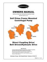
OWNERS MANUAL
INSTALLATION, REPAIR, AND OPERATING INSTRUCTIONS
S.A.E. Engine-Mount
Centrifugal Pump
IMPORTANT
For best possible performance and continuous, satisfactory operation,
read these instructions before installing your new pump.
Should service be required, this manual can be a valuable guide.
It should be kept near the installation for ready reference.
Record nameplate data from pump on blank nameplate inside this
manual for future reference.
Berkeley Pumps / 293 Wright Street / Delavan, WI 53115
F00636 (Rev. 7/21/09)

• SAFETY ...................................................................................................................................3
• INSTALLATION
General Information......................................................................................................3,4,5
Flywheel Coupling ...........................................................................................................6,7
Pump to Engine Assembly..................................................................................................8
Verify Rotation ....................................................................................................................9
Suction Connection .....................................................................................................10,11
Discharge Connection .................................................................................................12,13
• START-UP
Priming ........................................................................................................................14,15
Operation..........................................................................................................................15
• MAINTENANCE
General Information..........................................................................................................16
Packing Ring Replacement ..............................................................................................17
Impeller Removal..............................................................................................................18
Seal/Impeller Replacement ..............................................................................................19
Shaft Maintenance/Replacement .....................................................................................20
General Pump Care..........................................................................................................21
Routine Inspection Check List ..........................................................................................22
• PUMP NOMENCLATURE
General Information..........................................................................................................23
Parts Breakdown .........................................................................................................24,25
• TROUBLESHOOTING
Chart.................................................................................................................................26
Page 2 F00636
Table of Contents

F00636 Page 3
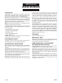
Safety First
General Information
READ AND FOLLOW
SAFETY INSTRUCTIONS!
This is the safety alert symbol. When you see this
symbol on your pump or in this manual, look for one
of the following signal words and be alert to the
potential for personal injury:
DANGER warns about hazards that will cause
serious personal injury, death or major property
damage if ignored.
WARNING warns about hazards that will or can
cause serious personal injury, death or major
property damage if ignored.
CAUTION warns about hazards that will or can
cause minor personal injury or property damage
if ignored.
The label NOTICE indicates special instructions
which are important but not related to hazards.
Carefully read and follow all safety instructions in
this manual and on pump.
Keep safety labels in good condition.
Replace missing or damaged safety labels.
General Safety
Do not allow pump, piping, or any other system com-
ponent containing water to freeze. Freezing may
damage system, leading to injury or flooding. Allowing
pump or system components to freeze will void
warranty.
Pump approved liquids only with this pump.
Periodically inspect pump and system components.
Wear safety glasses at all times when working on
pumps.
Keep work area clean, uncluttered and properly lighted;
store properly all unused tools and equipment.
Keep visitors at a safe distance from the work areas.
WARNING
Rotating parts. Can catch
hands, feet, or clothing.
Stay clear of equipment and
keep shields in place while
pump is running.
Stop motor or engine before
servicing pump.
Read owner’s manual before
using equipment.

Page 4 F00636
General Information
Installation
LOCATION
Locate the pump as near the water source as practical. Make
pipe run short, straight and with as few pipe fittings as pos-
sible, to keep total friction loss to a minimum.
Install pump in a clean, dry and drained location if possible
and protect against moisture and adverse weather conditions.
Pump should be located on a level, hard surface to prevent
shifting or tipping. Locate to be readily accessible for in-
spection and maintenance.
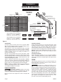
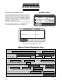
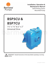
Because of the portable nature of this style pump, careful
attention should be taken to assure that Net Positive Suction
Head Available (NPSHA) exceeds Net Positive Suction Head
Required (NPSHR) by the pump or reduced performance and
severe pump damage may result.
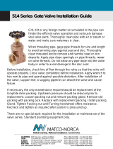
Figure 1, illustrates where these terms (NPSHA / NPSHR)
come from, and how to determine if the pumping conditions at
which you want to operate meet the proper criteria. When in
doubt, consult your nearest Berkeley Professional Dealer.
NOTE: If pump site is 1000 feet above sea level, subtract 1.2
feet from the NPSHA equation and an additional 1.2 feet for
each additional 1000 feet of elevation.
PUMP FOUNDATION
CRUSHING WEIGHT. Models with larger
suction and discharge openings are extremely heavy. Use care
and proper equipment when handling pump for installation.
Be sure to allow for the weight of the water in the pump and
piping.
Portable Installation:
Pump should be placed on an area that will provide a solid
foundation substantial enough to support the weight of pump
and engine and also to provide stability while the pump is
running. Engine vibration will cause shifting on any type of
loose surface and cause piping strains and possible damage.
NOTICE: Settling and/or shifting during operation can cause
piping to place excessive strain on the pump and may
damage pump case.
Permanent Installation:
Pump and Engine should be set on a concrete foundation
which is sufficiently substantial to absorb vibration and which
will provide a permanent and rigid support. Bolt engine directly
to concrete.
PIPING
System piping should be at least one commercial pipe size
larger than pump connections and flow velocity should not
exceed eight (8) feet per second.
Misalignment of piping with pump case or
excessive pipe strain can cause distortion of pump com-
ponents resulting in rubbing, breakage and reduced pump life.
Insure that piping is supported in a manner that prevents the
exertion of force on pump connections. If ANSI type flange
connections are used, this can be checked by the following
procedure. With the pump shut down, remove pipe flange
bolts. If the mating flanges come apart or shift, misalignment
is present and causing pressure on the connections. Adjust
pipe supports until flanges mate without any force. This
procedure can be done throughout piping system.
0 100 200 300 400 500 600 700 800 900
0
0
10
20
30
50
100
150
200
TDH
NPSH in Feet
Gallons Per Minute
NPSHR
EXAMPLE
ONLY
NPSHR at this point
= 10 Feet
NPSHR at this point
= 14 Feet
A Model B3ZQM operating at 500 GPM
with 80 Feet of Head has a NPSHR of.......... 10 Feet
at that point on the performance curve.
A Model B3ZQM operating at 600 GPM
with 68 Feet of Head has a NPSHR of.......... 14 Feet
at that point on the performance curve.
B3ZQM
1800 RPM
NPSHA
7 Feet
Static Lift
Static Lift = 7.0 Feet 7.0 Feet
9.5 Feet
16.5 Feet
16.5 Feet
Theoretical static
lift of centrifugal
pump at sea level =
Total = 15.5 Feet
Total Friction Loss = 8.5 Feet
Safety Factor - 6.0 Feet
Minus 15.5 Feet
Practical Limit = 28.0 Feet 28.0 Feet
NPSHA = 12.5 Feet
8.5 Feet total friction loss
@ 500 Gallons per minute.
9.5 Feet total friction loss
@ 600 Gallons per minute.
34.0 Feet
OK
NPSHA = 11.5 Feet
CAVITATION
6044 0609
500 GPM 600 GPM
Figure 1
EXAMPLE
ONLY

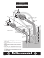
SUCTION PIPING
Refer to illustrations on Page 10 and 11 for recommended and
not recommended practices in suction connections.
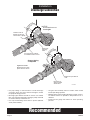
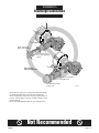
DISCHARGE PIPING
Refer to illustrations on Page 12 and 13 for recommended and
not recommended practices in discharge connections.
REQUIREMENTS FOR PROPER OPERATION
Pump End:
When delivering the required capacity (GPM) to the system
piping, the pump must add the amount of Head required by
the system at that capacity. The operating head-capacity point
should be as close as possible to the highest efficiency line
shown on the performance curve, and MUST be below the
head-capacity line labeled “Maximum” RPM. The maximum
operating RPM for the pump is determined by bearing life, or
in some cases, by the pressure limits of the pump. “The
maximum working pressure for NPT tapped and flanged
pumps, per ANSI B16.1 class 125, is 175 PSI unless
otherwise stated on the pump curve”. When used as a booster
pump, the pressure at the pump discharge (combination of
inlet pressure plus pressure added by the pump) must not
exceed the maximum working pressure shown. The Suction
NPSHA must be greater than the NPSHR shown on the pump
curve.
Engine:
The engine used to drive the pump must be suitable for the
application. It must produce adequate power for the pump
demand, and must rotate in the correct direction (standard
rotation is CLOCKWISE when viewed from the front of
engine).
Internal Combustion Engines are variable speed and variable
power machines. The power output depends upon the engine
speed (RPM) and will be reduced when operating altitude,
and/or the air temperature increases. When driving the pump
at the RPM required to deliver water into the system piping,
the engine must operate within the engine manufacturers
minimum and maximum RPM limits. The power output to
supply the pump power demand must not exceed the
CONTINUOUS POWER RATING of the engine, after derating
for all power consuming engine accessories, and adjustment
for installation site altitude and air temperature. Proper power
matching of the pump and engine is the responsibility of the
pump and engine unit assembler.
MATCHING PUMP END TO ENGINE
S.A.E. Bracket Size:
Type “B” engine drive pumps are available to fit engines
having a standard S.A.E. 5 through S.A.E. 1 flywheel housing.
For a new engine, the engine supplier can provide the S.A.E.
housing number.
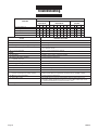
For an existing engine, the flywheel housing bore and bolt
circle can be measured and compared against the standard
S.A.E. housing dimensions listed in Table I, to identify the
housing S.A.E. number.
• Measure the flywheel housing bore (A), and the bolt circle
(B), as accurately as possible with a tape measure (to the
nearest 1/32 inch).
• Count the number of threaded holes in the flywheel housing
(C). Test the threaded holes with a bolt, to determine the
thread series.
• Compare the measured dimensions (A), (B), and (C) against
Table I, to determine the S.A.E. number of the flywheel
housing, to be sure it matches the S.A.E. number of your
pump.
• Record measurements on the dimension form on Page
23 in the spaces provided under Flywheel Housing
Dimension.
F00636 Page 5
General Information
Installation
ENGINE
A
B
C
Flywheel
Housing
Dimensions
20-1/8
20-7/8
12
7/16-14
17-5/8
18-3/8
12
3/8-16
16-1/8
16-7/8
12
3/8-16
14-1/4
15
12
3/8-16
12-3/8
13-1/8
8
3/8-16
A
B
C
12345
S.A.E. Flywheel Housing Size
No.
Size
TABLE 1
Figure 2

FLYWHEEL COUPLING
The flywheel coupling transmits power from the engine
flywheel to the pump shaft. The maximum power that a
coupling can safely handle is shown by a rating number, “R”,
which is listed in the coupling dimensions tables.
When selecting a flywheel coupling for a pump and engine,
first determine the power rating that the pump will demand.
On the pump performance curve, find the RPM and BHP
values required to produce the application head-capacity
point.
Divide the BHP by the RPM, then multiply the result times
100. The result will be the
demand number
for the pump.
For example, a B6JQBM can deliver 1500 GPM
at 260 feet Total Head when running at 2200
RPM. The power required by the pump will be
120 BHP. The demand number will be:
(120/2200) x 100 = 5.45
Next, select a coupling that can safely transmit the power, and
which will fit the flywheel dimensions. For a coupling to be
suitable, it must have an “R” rating number
GREATER
THAN
the pump
demand number
. In the above example, the
minimum coupling “R” number would be 6.
NOTE: The isolator disc design of Berkeley flywheel
couplings provides smooth power flow from the engine to the
pump, and torsional vibration problems are rare. However,
with the broad range of engines available, a torsional
mismatch can occur, which can cause excessive stress in the
pump shaft and coupling.
Torsional compatibility of the engine, pump, and coupling is
the responsibility of the assembler. Berkeley Pumps will
supply data for the pump and coupling for use by the
assembler for a torsional analysis.
NOTE: If the flywheel is fitted with a pilot bearing pressed into
a bore at the center, remove it to avoid interference with the
pump shaft.
FLYWHEELS FOR INDUSTRIAL TYPE
OVERCENTER CLUTCHES
Figure 3 on the facing page, shows the hollowed-out
appearance of the flywheels made for use with overcenter
type Clutch Power Take-Off assemblies.
These flywheels will have a recessed bore machined into the
face, and a set of tapped holes, which will be used to attached
the coupling to the flywheel. Dimensions are governed by an
SAE standard and are listed in Tables IIA and IIB, Figure 3.
The “Clutch Size” shown in the table is the nominal clutch
facing diameter for Drive Ring Type Overcenter Clutches.
For a new engine, the engine supplier can furnish the dim-
ensions.
For an existing engine, measure the flywheel dimensions, “D”
through “H”, using a tape measure and a machinists com-
bination square. Measurements to the nearest 1/32” will
usually be adequate.
When dimensions match a standard flywheel coupling listed in
Tables IIA, IIB, and IIC, Figure 3, select the one that has an
“R” rating number greater than the pump demand number.
• Record measurements on the dimension form on Page
23 in the spaces provided under Flywheel Dimensions.
OTHER FLYWHEELS
Some engines are fitted with flywheels especially machined
for coupling to other kinds of machinery (electrical generators,
torque converters, etc.), and require nonstandard flywheel
couplings. If the measured flywheel dimensions do not
correspond to dimensions listed in Tables IIa or IIb, write the
measured dimensions into the Dimension Form provided on
page 23, and send it to Berkeley for quotation of special
flywheel coupling.
Page 6 F00636
Flywheel Couplings
Installation

F00636 Page 7
Flywheel Couplings
Installation
E
BC
D
G
H
BC
Engine
Flywheel
Coupling
F
Spline
Diameter
-10T
(Spline Count)
Figure 3
Flywheels for Industrial
Type Overcenter Clutch
TABLE IIA – WIDE RPM RANGE, ELASTOMER MOUNTED HUB
Flywheel Dimensions Flywheel Coupling
Clutch D Catalog Shaft Spline
Size Qty. Size (UNC) E BC F G H R Number Diameter
6-1/2” 6 5/16-18 8-1/2” OD 7.88 3.94 1.19 1.69 7 B85397 1-3/8” 10T
6-1/2” 6 5/16-18 8-1/2 OD 7.88 3.94 1.19 1.69 7 B85398 1-1/2” 10T
7-1/2” 8 5/16-18 9-1/2” OD 8.75 3.69 1.19 1.69 7 B85399 1-3/8” 10T
7-1/2” 8 5/16-18 9-1/2” OD 8.75 3.69 1.19 1.69 7 B85400 1-1/2” 10T
8” 6 3/8-16 10-3/8” OD 9.62 4.81 2.44 2.94 7 B85401 1-3/8” 10T
8” 6 3/8-16 10-3/8” OD 9.62 4.81 2.44 2.94 7 B85402 1-1/2” 10T
10” 8 3/8-16 12-3/8” OD 11.62 4.47 2.13 2.75 7 B85403 1-3/8” 10T
10” 8 3/8-16 12-3/8” OD 11.62 4.47 2.13 2.75 7 B85404 1-1/2” 10T
11-1/2” 8 3/8-16 13-7/8” OD 13.12 5.06 1.56 2.69 7 B85405 1-3/8” 10T
11-1/2” 8 3/8-16 13-7/8” OD 13.12 5.06 1.56 2.69 7 B85406 1-1/2” 10T
TABLE IIB – HEAVY DUTY, ELASTOMER MOUNTED HUB
Flywheel Dimensions Flywheel Coupling
Clutch D Catalog Shaft Spline
Size Qty. Size (UNC) E BC F G H R Number Diameter
10” 8 3/8-16 12-3/8” OD 11.62 4.47 2.13 2.75 9 B85407 1-3/8” 10T
10” 8 3/8-16 12-3/8” OD 11.62 4.47 2.13 2.75 9 B85408 1-1/2” 10T
11-1/2” 8 3/8-16 13-7/8” OD 13.12 5.06 1.56 2.69 9 B85409 1-3/8” 10T
11-1/2” 8 3/8-16 13-7/8” OD 13.12 5.06 1.56 2.69 9 B85410 1-1/2” 10T
14” 8 1/2-13 18-3/8” OD 17.25 6.63 1.00 2.13 9 B85411 1-1/2” 10T

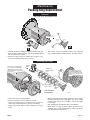
PREPARATION FOR ASSEMBLY
OF PUMP ON ENGINE
• Clean face and register fit of flywheel housing and flywheel
as necessary to remove all grease, dirt, or rust (and all
traces of rust preventative) which would interfere with
installation of pump and/or prevent correct alignment. If
flywheel is fitted with a pilot bearing for a transmission shaft,
remove and discard. The pilot bearing is not required for
installation of the pump end, and could interfere with the
pump shaft.
• Examine shaft spline closely. Use a file, if necessary, to
remove any burrs that would prevent coupling from sliding
freely onto the shaft.
• Lubricate pump shaft spline sparingly with light grease.
• Slide the coupling onto shaft until it is stopped against the
shaft.
• Measure the distance from the engine side of flywheel
coupling adapter ring to the mounting face of the pump
bracket. Refer to Figure 4 below, Dimension “A”.
• Next, measure depth from face of flywheel housing on
engine, to face on flywheel against which coupling will be
bolted. Refer to Figure 4 below, Dimension “B”.
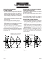
Pump measurement must be less than engine measurement
or axial interference will result in thrust force on engine crank
shaft bearings. Simply stated, Dimension “A” must be less
than Dimension “B”.
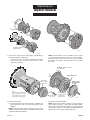
INSTALLATION OF COUPLING ON FLYWHEEL
Flywheel Coupling Overcenter Type:
These couplings are aligned concentrically with the flywheel
by register fit on the flywheel.
Be sure to remove all preservatives from the engine’s
flywheel.
Fit the coupling into the flywheel. Align the bolt holes and
engage coupling with register fit on flywheel. Tap coupling
with a soft heavy hammer, if necessary, to be sure that it is
seated flat against flywheel. Secure coupling tightly to
flywheel with capscrews and lockwasher.
INSTALLATION OF PUMP ON ENGINE
• Lift pump with suitable lifting apparatus and align pump
shaft with coupling. End of pump shaft has a pilot diameter
which permits easy engagement of pump shaft into
coupling.
• Reach into pump suction opening and rotate impeller
slightly until the splines on the shaft will engage the
coupling. Verify that there is no gap between bracket and
flywheel housing faces. Rotate pump as necessary to align
bracket holes with engine. Install capscrews and bolt pump
end securely to engine.
NOTE: If any interference, or incompatibility of parts is
detected during installation, DO NOT proceed with
assembly. Direct the problem to your nearest Berkeley
Professional Dealer.
Page 8 F00636
Pump To Engine Assembly
Installation
B
A A
Engine
Pump
Bracket
Pump
Bracket
NOTE: When the coupling is correctly assembled,
the hub will not bottom out on the shaft splines.
If it should bottom out, reverse the coupling on
the shaft as shown to gain clearance.
Dimension "A" MUST be
less than dimension "B".
(No Go – A is
longer than B)
(Go – A is
shorter than B)
4021 0801
Figure 4
Engine
= Check for Clearance
before operating pump.
Preferred
Installation
Alternate
Installation
Pump
Bracket
4022 0801
Figure 5

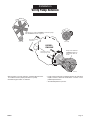
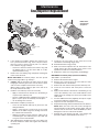
• Before pump is put into operation, rotational direction must
be verified to assure proper performance of pump.
• Standard engine rotation is clockwise.
• Pump running backward: Centrifugal pumps will still pump
liquids, however, GPM and head will be a fraction of the
published performance.
• Threaded impellers may loosen.
F00636 Page 9
Verify Pump Rotation
Installation
DIESEL
ENGINE
C
l
o
c
k
w
i
s
e
r
o
t
a
t
i
o
n
View-"A" looking
toward fan.
View-"B" looking
toward pump shaft.
Pump volute indicates
clockwise
rotation as
viewed from driver as
shown.
If Engine fan is rotating
clockwise
as viewed, a pump
with
clockwise
rotation is required.
View-"A" View-"B"
C
l
o
c
k
w
i
s
e
r
o
t
a
t
i
o
n
6046 0609

Page 10 F00636
Suction Connection
Installation
Portable and Permanent
Recommended
As close
as possible
Pipe
Diameter
"D"
Rigid Wall Flexible
Suction Hose with
quick connect shown.
Eccentric Reducer
flat side up.
Short length of
straight pipe.
(2 times pipe diameter)
Connection for remote hand primer
or for manual priming.
4 x "D"
minimum
1 x "D" minimum
from bottom
Strainer / Foot Valve
To keep debris from entering
pump suction and to maintain
pump prime after shut-off.
Connection for optional Engine Exhaust
Primer. Locate at least one (1) pipe
diameter from pump case.
Portable Installation is most
common with this style pump.
Typical of permanant
installation using standard
pipe and fittings.
Suction
Gauge
Eccentric Reducer
flat side up.
Support pipe
as required
Standard or long
radius elbow.
Slope upward
to pump.
Straight run, short as possible but
at least 6 times pipe diameter ("D")
after elbow to stabilize flow.
All connections must
be
air tight.
NOTICE:
Companion
Flange Kit
Companion
Flange Kit
Companion
Flange Kits
• Recommendations called out in field of drawing apply to
both suction connections shown.
• Use pipe, tubing or reinforced hose to make suction con-
nection. Hose must have sufficient strength to resist col-
lapse under pressure differential that occurs while pump is
running.
• Suction pipe size should be at least one commercial pipe
size larger that opening in pump inlet. Flow velocity should
not exceed 8 ft./sec.
• Suction screen area must be at least four times suction pipe
area.
• Net Positive Suction Head Available (NPSHA) must exceed
Net Positive Suction Head Required (NPSHR) by the pump
or reduced performance and severe pump damage may
result.
• All suction piping must have a continuous rise to the pump
suction inlet. For rigid pipe or tubing, a 1/4 inch per foot
minimum slope is recommended.

F00636 Page 11
Suction Connection
Installation
Portable and Permanent
Not Recommended
Pipe diameter
("D") undersized
reduces performance
Unsupported pipe
causes excessive
stress on pump and
fittings.
Do not install valves
in suction line.
No support or uneven
mounting not recommended.
Excess use of pipe fittings
means potential
air leaks.
Long run
not
recommended
Concentric Reducer causes
high spots along the suction line
resulting in
air pockets.
High suction
lift should be
avoided
High spot in suction
hose may result in
air pocket.
Avoid suction hose that may collapse
during operation due to insufficient
strength.
No strainer may
cause pump to
clog.
Insufficient bottom
clearance.
Vortex caused by
insufficient submergence
may cause pump to
lose prime.
Less than
4 x "D"
• Callouts in field of drawing apply to both suction con-
nections shown.
• Elbow immediately in front of pump intake not recom-
mended.
• Suction pipe sloping downward to pump inlet will trap air
which will reduce performance and may cause pump to
lose prime.
• Suction piping that is undersized will create excess friction
losses that may cause cavitation and a reduction in pump
performance.
• Excess fittings and bends in suction line results in trapped
air, reduced performance, and high friction losses which
may cause cavitation.

• Use pipe, tubing or reinforced hose to make discharge
connection. Hose must have sufficient strength to contain
the pump discharge pressure.
• Discharge pipe diameter should be at least one nominal
pipe size larger than discharge opening in pump and sized
so that flow velocity is below 8 ft./sec.
• Use only non-slamming check valves to prevent hydraulic
shock (water hammer).
• Use gate, ball or butterfly valve for isolation. Valve should
be full open during operation.
• Maintain proper size throughout discharge system, using as
few elbows and tees as possible to keep friction loss to a
minimum.
• Install pressure gauge after reducer to check operating
pressure.
Page 12 F00636
Discharge Connection
Installation
Recommended
Rigid Wall Flexible
Discharge Hose with
quick connect shown.
All connections must
be
air tight.
NOTICE:
Non-Slam or
spring loaded
check valve.
Expansion joint with tie
rods.
Isolation valve to
permit servicing of
check valve or pump.
Discharge
Priming
Valve
Use Concentric reducer
to minimize friction losses.
Support piping
as required.
6049 0609

• Avoid excess friction loss caused by numerous fittings,
insufficient pipe diameter, and sharp turns in pipe run.
• Some swing type check valves may permit buildup of
reverse velocity before closing, causing hydraulic shock
(water hammer).
• Do not force pipe alignment that can cause flange stress.
F00636 Page 13
Discharge Connection
Installation
Not Recommended
Do not use Gate Valve
to throttle flow.
Avoid abrupt change
in pipe size.
Avoid undersized
pipe / hose diameter
Do not leave
pipe unsupported
6050 0609
Avoid check valves
that cause hydraulic
shock.

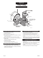
Installations With Suction Lift and Priming Pump.
• Close air tight valve on discharge.
• Hand primer operation:
1. Open the hand primer isolation valve.
2. Work handle of the hand primer up and down to evacuate
air from the suction line.
(Refer to primer owner’s manual for proper pro-cedure).
3. When water flows freely from primer, close the hand primer
isolation valve.
(Pump case should now be filled with water).
• Immediately start pump.
• Slowly open discharge valve (if used).
(Discharge Priming Valve will open automatically).
Installations With Suction Lift and Exhaust Primer.
• Locate exhaust primer connection as shown above.
• For complete operation, refer to specific instructions in-
cluded with exhaust primer, or consult your nearest
Berkeley Professional Dealer.
Installations With Suction Lift and Foot Valve.
• Close air tight valve on discharge.
• Remove pipe plug from highest opening on pump case.
• Completely fill pump and suction piping with water.
• Rotate shaft slowly allowing any air trapped in impeller to
escape.
• When all air has been forced out of pump, replace pipe
plug. Use pipe joint compound on plug threads and tighten
as necessary to prevent leakage.
Installations With Flooded Suction.
• Open air vent (or pipe plug) in the highest tapped opening
in pump case.
• Open inlet isolation valve, full open, allowing water to fill the
pump completely and force all air out through vent.
• Rotate shaft slowly allowing any air trapped in impeller to
escape.
• Close vent opening when water without air emerges.
Page 14 F00636
Pump Priming
Start-Up
Primer Isolation
Valve
Berkeley Discharge
Priming Valve or
Isolation Valve.
Hand
Primer
Suction to
Water Source
6051 0609
For Engine Exhaust Primer
Locate connection at least
one pipe diameter from
pump case.

PRIMING
Pump priming is the displacement of air with water in the
pump and suction piping. Pump MUST BE completely filled
with water when operating.
Refer to Page 14 for instruction on the following conditions:
1. Suction lift with priming pump (water source below pump).
2. Suction lift with exhaust primer (water source below pump).
3. Suction lift with foot valve (water source below pump).
4. Flooded suction (water source above pump, or incoming
water pressure is greater than atmospheric pressure).
Special Case – Hydraulically Balanced Pumps
Packed Pumps:
Hydraulically balanced pumps operate at a very low positive
pressure across the stuffing box, permitting a much looser fit
of the packing rings around the shaft sleeve to control the loss
of water from the pump through the stuffing box. Because of
the looser fit of the packing rings, air can be more easily
drawn into the pump through the stuffing box when priming
the pump with an air evacuation type primer.
A grease fitting, communicating through the side of the
stuffing box to a lantern ring in the packing set, is provided to
grease-seal the stuffing box to prevent air leakage during
priming.
If pump cannot be primed due to air leakage through stuffing
box, DO NOT tighten packing. Instead, pump NLGI No. 4
Water Pump Grease into lantern ring until back pressure
occurs forcing grease into the lantern ring, grease sealing the
stuffing box. After priming, when unit is put into operation, the
grease will be flushed out through the packing by the water
flowing outward through the stuffing box. Proceed with normal
adjustment of the packing as described on Page 17. Note that
the grease seal only is used for control of air leaking during
priming, and that only the packing gland is used to control the
flow of water the stuffing box during normal operation.
When necessary to replenish the grease supply, use an NLGI
No. 4 Water Pump Grease.
Mechanically Sealed Pumps:
Mechanically sealed pumps require no special procedures
unless they are mounted vertically. In this case, call Berkeley
Customer Service at 1-888-237-5353 for more information.
STARTING
Never run pump dry. Running pump without
water will overheat pump and damage internal parts. Always
make sure pump is primed prior to start-up.
Engine Operation
Refer to engine owner/operator manual supplied with pump for
starting and operating instructions.
Pump performance varies depending on engine RPM. Refer to
engine operators manual to adjust engine speed.
Risk of Engine Damage. Operating pump at
lower than rated head can cause excessive load on engine. In
addition, pump has the capability of overloading engine if
allowed to run continuously at an RPM or flow rate that is
above specified hydraulic performance.
Risk of pump damage. Operate the engine in
its preferred RPM range. Reduced RPM for long periods may
damage the pump liquid end.
Pump Operation
Prime pump by one of the previous described procedures.
Start engine. Slowly open discharge valve until desired flow
rate is achieved, or pump is operating against head for which it
was selected.
After pump is running, allow packing to leak liberally for a few
moments. Then tighten gland nuts one complete turn each
until leakage is reduced to 40 to 60 drops a minute.
If pump is equipped with a rotary mechanical seal, no
adjustment is necessary.
Shutting Down
Close discharge valve to hold prime before stopping pump.
Valve should remain closed until pump/engine is restarted.
Reduce the engine RPM prior to shutting down to reduce
hydraulic shock (water hammer).
F00636 Page 15
Pump Priming
Start-Up

LUBRICATION
LIQUID END of pump requires no lubrication. Wear rings,
packing rings, and models using a mechanical shaft seal, are
lubricated by the liquid being pumped. Do Not Run Dry!
BRACKET: Add approximately 2 oz. of a lithium-based NLGI
No. 2 extra pressure ball bearing grease to each bearing
during quarterly inspection. Refer to pump parts drawing on
Page 24, grease fittings are labeled with a circled “L”.
Excessive grease will cause bearings to run hot.
NOTE: Grease fitting in packing area is for priming only. See
Priming
in start-up section for instruction.
The following brands of bearing grease are factory approved
by Berkeley Pumps and are recommended for use in main-
tenance operations.
• Shell Brand Alvania Grease EP2
• Mobil Oil brand Mobilith AW#2
• Exxon Ronex MP
• Atlantic Richfield Litholine EP2
• Amoco Amolith EP2
ENGINE: Refer to engine manufacturer’s operating manual
for complete maintenance instructions.
PERFORMANCE CHECK
Periodically check the output of the pump. If performance is
noticeably reduced, refer to Troubleshooting Chart.
OBSERVATIONAL MAINTENANCE
When the pump and system operation have been stabilized,
verify that pump unit is operating properly. Observe the
following:
VIBRATION: All rotating machines can be expected to
produce some vibration, however, excessive vibration can re-
duce the life of the unit. If the vibration seems excessive, dis-
continue operation, determine cause, and correct.
NOISE: When the unit is operating under load, listen closely
for unusual sounds that might indicate that the unit is in dis-
tress. Determine the cause and correct.
OPERATING TEMPERATURE: During operation, heat is
dissipated from the pump and the driver. After a short period
of time, the surface of the pump bracket near the bearings will
be quite warm (as high as 150° F), which is normal. If the
surface temperature of the pump bracket or engine is
excessive, discontinue operation, determine cause of
temperature rise, and correct. Bearings will run hotter for a
brief run-in period after packing, which is normal. However,
worn bearings will cause excessive temperatures and need to
be replaced. The pump unit is cooled by the water flowing
thorough it, and will normally be at the temperature of the
water being pumped.
STUFFING BOX. After a short period of operation, verify that
the stuffing box area and gland are not hot. If heating is
detected, loosen the gland nuts evenly until water is just
running out of stuffing box in
DROPLET
form (40 to 60 drops
per minute). Water must not be streaming or spraying out.
Verify cool operation periodically. Adjust gland nuts
EVENLY
as necessary for lubrication and cooling of the packing. If
packing has been tightened to the limit of the packing travel,
additional packing is necessary.
REPACKING
Refer to illustration on Page 17.
MECHANICAL SEAL
Adjustment or maintenance is not required. The seal is
enclosed within the pump and is self-adjusting. Seal is cooled
and lubricated by the liquid being pumped.
PUMP PROTECTION – COLD WEATHER/
WET WEATHER INSTALLATIONS
SYSTEM DRAINS: Provide drain valves to empty system,
including pump case, to prevent freezing damage.
SHELTER: If possible, provide shelter for unit to protect from
weather. Allow adequate space around pump unit for service.
When effectively sheltered, a small amount of heat will keep
temperature above freezing. Provide adequate ventilation for
unit when running.
CONDENSATION: When the temperature of metal parts is
below dew point and the surrounding air is moist, water will
condense on the metal surfaces and can cause corrosion
damage. In severe situations, a space heater can be
considered to warm the unit.
Page 16 F00636
General Information
Maintenance

• Unfasten hardware holding packing gland in place and slide
back on shaft to expose packing rings. A split packing gland
with threaded studs is shown.
• Remove packing rings from stuffing box using two com-
mercially available packing hooks as shown.
• Slide lantern ring (if used) back to expose any remaining
rings, including metallic. Remove them in the same manner.
F00636 Page 17
Packing Ring Replacement
Maintenance
Removal
Packing
Gland
Packing
Hooks
Packing
Ring
Shaft
Shaft
6052 0609
Pump liquid end removed
for pictorial clarity only.
1
2
Packing
Gland
Shaft
BERKELEY
Pump liquid end and packing
insert removed for pictorial
clarity only. Remove packing
gland and packing rings through
frame cutout.
Metallic
Ring
Lantern Ring
(stays on shaft)
Stagger ring
joints 90 degrees
apart.
Packing
Rings
Typical Packing
Arrangement
Pump liquid end removed
for pictorial clarity only.
Remove packing gland and
packing rings through frame
cutout.
6053 0609
Installing New Rings
• Clean shaft sleeve and packing gland.
• Inspect shaft sleeve for wear, replace if needed.
• Install new packing rings in stuffing box by placing over
shaft sleeve and pushing them in as far as they will go.
• Rotate ring joint 90 degrees when installing each ring as
shown.
• Slide packing gland into position (gland must enter stuffing
box bore) then gently and evenly tighten nuts to force rings
into place and seat (do not over tighten). Loosen nuts again
to hand tight.
• Start primed pump and allow packing to leak liberally.
• While pump is running, evenly tighten gland nuts one
complete turn at a time until leakage is reduced to droplet
form (40 to 60 drops per minute).
See Page 19 for Seal Replacement.

Page 18 F00636
Impeller Removal
Maintenance
Clockwise Rotation
Volutes shown.
6054 0609
1. Remove the volute and the old gasket(s) and O-Ring(s).
Discard the gaskets and O-rings.
• Check the clearance between the impeller hub and the
volute wear ring. If it is more than .020” on a side,
replace the wear ring.
NOTE: Certain models, such as the B4EY, have a suction
cover which is removed first to gain access to the impeller.
On these models, remove the access cover, then remove
the impeller (see below), and then remove the seal from
the volute.
2. Remove the impeller:
A. Pull keyed impellers off the shaft with a standard gear
puller against the end of the shaft and pulling on the
impeller.
NOTE: Place the puller’s fingers against the vanes in the
impeller. Pulling on the impeller’s unsupported back shroud
could easily break the impeller.
B. Unscrew threaded impellers.
NOTE: Pumps with clockwise rotation as viewed from the
shaft (engine) end have a right-hand threaded impeller.
Pumps with counterclockwise rotation as viewed from the
shaft (engine) end have a left-hand threaded impeller. The
impeller cap screw is always right-hand thread.
BERKELEY
4041 0901
BERKELEY
R
E
M
O
V
E
Clockwise rotation as viewed
from shaft end.
Right Hand Thread
Hold pump shaft
stationary, being
careful not to
damage shaft.
Impeller will be
extremely tight
on shaft.
Key
Gear Puller
Jackscrew
Note:
A hexnut placed between the
jackscrew and shaft end will
prevent damage to the shaft
and impeller screw threads.
6055 0609
Gear Puller
Fingers behind
Impeller Vanes

3. If your pump has a bolted in balance ring, remove it; if it
has a pressed in balance ring, leave it in place unless
there isn’t room to get the seal out past it. If it doesn’t
have a balance ring, go to Step 4.
• Check the clearance between the balance ring and
the impeller hub. If it is more than .020” on a side,
replace the balance ring.
4. Remove the seal retaining ring and pull the rotating part
of the seal off the shaft.
Model B4EYQBHS and similar pumps: See the special
section on this page. Others: go to Step 5.
5. Z Series: Pull the seal plate out until it clears the shaft,
bringing the stationary part of the seal out with it. Tap the
seal out of the seal plate and clean the seal cavity.
Other Pumps: Pull the stationary part of the seal out of
the cavity and clean the cavity.
6. Install the new stationary seal in the seal cavity.
• Apply a small amount of mineral oil to the O-Ring or
cup seat of the stationary seal.
• Use the cardboard washer (supplied) and a piece of
pipe as a press; press the stationary seal into place.
• Do not damage the seal face!
7. Reinstall the seal plate (if used) now.
• Cover all shaft threads with tape to protect the seal
during installation.
• Apply a small amount of mineral oil to the inside
diameter of the rubber ring in the rotating seal and to
the outside of the shaft sleeve.
• Slide the seal plate over the shaft now, taking care to
avoid damage to the stationary part of the shaft seal
as it goes over the shaft shoulder.
8. After lubricating the rotating part of the seal, slide it onto
the shaft and sleeve until it seats against the stationary
(ceramic) part.
9. Compress the seal spring on the shaft sleeve and
reinstall the seal retaining ring (if used).
10. Reinstall the balance ring (if used).
11. Slide or thread the impeller onto the shaft until it seats
solidly against the shaft shoulder, then install a new
impeller screw with its associated hardware.
12. Replace the volute. Use new gasket(s) and O-Ring(s).
B4EYQBHS and similar pumps (See Picture Above):
After STEP 4, you will need to:
A. Remove the bracket from the engine.
B. Remove the outer bearing cap and slide the shaft
assembly back out of the bracket.
C. Remove the seal retainer and tap out the stationary seal.
D. Clean the seal retainer and shaft (don’t scratch the
shaft!).
E. Apply a small amount of mineral oil to the O-Ring or cup
seat of the stationary seal, to the inside diameter of the
rubber ring in the rotating seal, and to the outside of the
shaft sleeve.
F. Use the cardboard washer (supplied) and a piece of pipe
to press the stationary seal into place.
G. Inspect the oil seal and replace it if necessary.
H. Repack the bearings and reinstall the shaft in the bracket.
NOTE: When the end of the shaft comes through the
front bearing bore in the bracket, slip the slinger and seal
retainer over the end of the shaft. BE SURE you don’t
damage the seal face on the shaft shoulder!
J. Reinstall the outer bearing cap with a new gasket and
proceed to STEP 7 (“Reinstall the shaft sleeve....”)
F00636 Page 19
Seal/Impeller Replacement
Maintenance
1
3
2
Remove seal
plate
6056 0609
A
B
C
B4EY Series
Seal Change
Sequence

Page 20 F00636
• Remove volute to expose impeller.
• Peel off old volute gasket (or O-Ring) and discard.
NOTE: Certain models such as the B4EY, are constructed
with a suction cover which is removed first to access impeller.
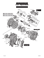
GENERAL
• Shaft assembly of S.A.E. mounted pumps should be
periodically (annually minimum) torn down for inspection of
worn parts, cleaning, and re-greasing. Most importantly, to
check shaft sleeve and bearings for pitting. Replace worn
components as necessary. Parts may be ordered sepa-
rately as required, or for some models, shaft kits are
available that are completely assembled and ready for
installation.
PUMP DISASSEMBLY
• Remove packing gland and packing arrangement as
described in Page 17.
• Remove pump volute and impeller as described on Pages
18 and 19.
• Remove outer bearing cap and slide shaft assembly from
bearing bracket.
• Clean and inspect all components.
SHAFT INSTALLATION
• Thoroughly steam clean or solvent wash the bearing cavity
of bracket to remove old grease and dirt. Check surface of
bracket for cracks, extreme corrosion, or other defects.
• Pack bearings with a lithium-based NLGI No. 2 extra
pressure ball bearing grease (see “Lubrication”, Page 16).
Force enough grease into each bearing to fill internal space
between the races.
• Coat the bearing bores of bracket with oil. Orient shaft
assembly in the direction shown above. Slide shaft and
bearing assembly into bearing bracket.
Do not force them!
When threaded end of pump shaft comes through inside
opening of bearing cavity, place oil seal, water slinger, and
lantern ring over end of shaft. If packing gland or seal
retainer is not of the split variety, place it over the shaft at
this time as well. Slide shaft on through stuffing box until the
first bearing makes contact with the bracket. Carefully align
bearing with the bearing bore and press or tap bearing
assembly into place. Do not use excessive force.
NOTE: Be sure bearing bores and bracket area are clean and
free of contamination or early bearing failure may occur.
• Reinstall outer bearing cap and oil seal.
• Rotate pump by hand, 10-12 rotations.
• Reassemble pump parts and reinstall unit to piping system.
Refer to
Installation
section in this manual for correct
procedure.
Shaft Maintenance/Replacement
Maintenance
Outer Bearing Cap
with Grease Seal
Outer Bearing Cap
Water
Slinger
Oil Seal
Water
Slinger
Oil Seal
Make sure bearings are clean;
pack with grease as shown.
Procedure and parts may vary slightly
depending on pump model.
6057 0609
Procedure and parts may vary
slightly depending on pump model.
Page is loading ...
Page is loading ...
Page is loading ...
Page is loading ...
Page is loading ...
Page is loading ...
Page is loading ...
Page is loading ...
-
 1
1
-
 2
2
-
 3
3
-
 4
4
-
 5
5
-
 6
6
-
 7
7
-
 8
8
-
 9
9
-
 10
10
-
 11
11
-
 12
12
-
 13
13
-
 14
14
-
 15
15
-
 16
16
-
 17
17
-
 18
18
-
 19
19
-
 20
20
-
 21
21
-
 22
22
-
 23
23
-
 24
24
-
 25
25
-
 26
26
-
 27
27
-
 28
28


Berkeley S.A.E. Engine-Mount Centrifugal Pump Owner's manual
- Category
- Water pumps
- Type
- Owner's manual
Ask a question and I''ll find the answer in the document
Finding information in a document is now easier with AI
Related papers
-
Pentair Self Prime Frame Mounted Centrifugal Pump Owner's manual
-
Berkeley B2X, B3T, B4T, B4Z Close Coupled Motor Drive Self Priming Centrifugal Pump Owner's manual
-
-
-
-
-
-
-
-
Other documents
-
Vantec AeroFlow FX 92 User manual
-
 VOV VAC-11013 Datasheet
-
Laufen 9506781 Installation guide
-
Poolmaster 27402 Operating instructions
-
 Berkley B4ZRKS User manual
-
AMT 3941-96 Installation guide
-
 Barmesa BSP5CU Installation guide
-
Aurora 495 Owner's manual
-
 Matco-Norca 514T10 Installation guide
-
Franklin Electric BT4 Series Owner's manual


