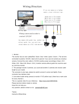
2. RS-485: Connect to a local keyboard controller.
DI/DO: Connect to sensor in and alarm out devices.
Cable for I/O connectors:
Name Cable Color Function
DC 12V Brown/White DC 12V (50mA maximum)
GND Blue/White GND
D+ Purple/White RS485 data +
D- Gray RS485 data -
DI Green/White Digital signal input
DO Orange/White Digital signal output
3. Reset Button
This button is used to restore the all factory default settings.
Sometimes restarting the device will make the system back to a normal
state. However, if the system still got problems after restart, user can
restore the factory default settings and install it again.
Restore the device:
a. Press the button down continuously.
b. Hold the button at least 5 seconds and release it. Then the device
has been restored to default settings and reboot again.
4. Power Jack
The input power is DC 12V.
1. Only use the power adapter supplied with internet
camera Otherwise, the product may be damaged.
2. The power adapter is unnecessary when internet
camera is connected to a PoE switch. Otherwise, the
product may be damaged when internet camera is
connected to a PoE switch and power adapter simul-
taneously.