
2008
Electrical fan for domestic use
"VV"and "VVR" series
MANUAL

2
Type
VV 180 VVR 180
VV 230 VVR 230
177 177
237 237
220-240
25 25 25
30 30 30
212 212
176
455 455
290
35 35 30 38 38 30
left
right
(reverse)
31 31 31 32 32 32
1400 1400 1400
1300 1300 1300
table 1
left left left
right
(reverse)
FUNCTIONS
Fans are designed to be used in domestic areas
(such as living quarters, offices, shops, garages,
kitchens, toilets and other quarters, that are
heated in the winter season).
Mentioned fans are of an exhaust (VV models)
and a draft-or-exhaust (VVR models) type, and
should be mounted on or inside of the walls, or in
windows.
VV and VVR fans has adjustable draft damper,
operated by an electrical servomotor.
The fans are designed to be used in temperature
o o
range of 0 C to 45 C.
Operation life minimum is 5 years.
The fans' design is being continuously improved, so some of the models
may differ from their description in this manual.
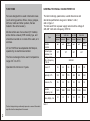
GENERAL TECHNICAL CHARACTERISTICS
The fans' markings, parameters, overall dimensions and
structural specifications are given in tables 1 and 2,
and on figure 1.
The fans work from a power supply network with a voltage of
220-240 V AC and a frequency of 50 Hz.
exhaust exhaust exhaust exhaustdraft draft
Rotation
direction
Exhaust pipe
diameter, mm
Voltage, V AC,
with a frequency
of 50 Hz
Power, W
3
Capacity, m /h
Pressure, Pa
Rotation
-1
frequency, min
Noice, dB(A), 3 m

VV 180
VV 230
VVR 180
VVR 230
figure 1
3
A
D
C
B
Type
VV 180
VV 230
VVR 180
VVR 230
А
230
295
С D
87
85
177
237
В
65
74
table 2
DELIVERY SET
Delivery set includes the following:
- fan - 1 item;
- certificate;
- package box;
- screws - 4 items;
- dowel - 4 items;
- joint - 1 item.
SAFETY REQUIREMENTS
Electric shock protection of he fans is a class 1.
Protection from a contact with dangerous parts and water
intrusion is on the IPX4 level.
The equipment should be mounted and maintained only by
persons, who had read this manual and who has a right to
independently service equipment with voltages over 1000 V.
Do not install and use these fans in places with air temperatures,
which exceed the stated temperature range, as well as in an
atmosphere, that contains corrosive vapors.
Never use the product, if any objects, capable of damaging the
fan blades, have got into an air intake.

4
1
D
1
D
figure 2
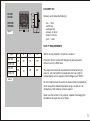
INSTALLATION
Make an opening D1 in a wall or in a glass:
for fans VV/VVR 180, D1=185 -188 mm; for fans VV/VVR 230, D1=247 - 250 mm.
Install the fan in the opening and secure it with the securing bars (figure 2) or with 4 screws, which fix the fan
to the wall by the dowels.
Then, install an exterior panel of the fan.

5
L
N
~
4
V
2
2
-
2
0
0
0
5 H
z
N
L1
L2
PE
S
L
N
~
4
V
2
-2
2 0
0
0
5
H
z
N
L1
L2
PE
L
N
~
4 V
2
-2
2 0
0
0
5
H
z
N
L1
В
L2
PE
HL
5
4
1
2
3
-
1
-
3
00
P
3
В
В
figure 3
figure 4
figure 5
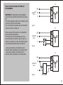
FANS' STRUCTURE AND SETTING-UP
PROCEDURES
WARNING! All maintenance and installation
works are to be performed with the main power
off.
The air flow direction must be in a direction, that
an arrow on the fan case shows.
For a VV series fan a power source connection
scheme is shown on figure 3.
When using a VVR series fan, it is possible to
reverse an air flow direction.
To connect such a fan and make use of its
reverse function, a switch S may be used, as
shown on a figure 4; or else, the switching may
be performed using the cable connections:
- when power cable is connected to an L2
terminal, the fan operates in an exhaust mode;
- when power cable is connected to an L1
terminal, the fan operates in an intake mode.

Model
Manufacture date
Acceptance stamp
Sold
Sellers' name, shop's stamp
F01EN -(VV_VVR)-02
VV 180
VVR 180
VV 230
VVR 230
check the right one
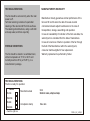
TECHNICAL SERVICING
The fan should be serviced only when the main
power is off.
Technical servicing consists of a periodical
cleaning of the dust and dirt from the surfaces.
The cleaning should be done, using a soft cloth
and soap water, and then wiped dry.
STORAGE CONDITIONS
The fan should be stored in a ventilated room,
o o
with air temperature of +5 C to +40 C and
o
humidity less than 80 % (at T=25 C), in a
manufacturer's package.
MANUFACTURER'S WARRANTY
Manufacturer hereby guarantees normal performance of the
fan over 60 months since the date of its sale via retail
commercial network subject to adherence to the rules of
transportation, storage, assembling and operation.
In case of unavailability of indication of the fan's sale date, the
warranty term is calculated from the date of manufacture.
In case of occurrence of faults in operation of the fan through
the fault of the Manufacturer within the warranty term,
consumer shall be eligible for free replacement.
Warranty replacement is performed by Seller.
TECHNICAL SERVICING
The fan is ready for operation
Sale date
-
 1
1
-
 2
2
-
 3
3
-
 4
4
-
 5
5
-
 6
6


Ask a question and I''ll find the answer in the document
Finding information in a document is now easier with AI
Related papers
Other documents
-
 Roger Technology E80 & M80 Owner's manual
-
Vacron VVG-CBN33 User manual
-
-
-
Star Micronics TSP400 Series User manual
-
-
-
-
-
Eclipse Popo User manual
