Emerson 66 Series Direct-Operated Regulators and Vacuum Service Equipment User manual
- Type
- User manual
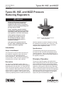
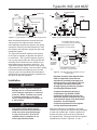
Emerson 66 Series Direct-Operated Regulators and Vacuum Service Equipment provide accurate regulation in a variety of applications. Their low-maintenance design makes the regulators suitable for the toughest conditions. The versatile equipment can be used for pressure reduction, vacuum regulation, and vacuum breaking. Additional features include:
- Easy installation and adjustment
- Sizes from 2 to 4 inches (DN 50 to DN 100)
- Pressure ratings up to 10 psig (0.69 bar)
- Vacuum ratings up to 29.9 inches of mercury (1.


-
 1
1
-
 2
2
-
 3
3
-
 4
4
-
 5
5
-
 6
6
-
 7
7
-
 8
8
-
 9
9
-
 10
10
-
 11
11
-
 12
12
-
 13
13
-
 14
14
-
 15
15
-
 16
16


Emerson 66 Series Direct-Operated Regulators and Vacuum Service Equipment User manual
- Type
- User manual
Emerson 66 Series Direct-Operated Regulators and Vacuum Service Equipment provide accurate regulation in a variety of applications. Their low-maintenance design makes the regulators suitable for the toughest conditions. The versatile equipment can be used for pressure reduction, vacuum regulation, and vacuum breaking. Additional features include:
- Easy installation and adjustment
- Sizes from 2 to 4 inches (DN 50 to DN 100)
- Pressure ratings up to 10 psig (0.69 bar)
- Vacuum ratings up to 29.9 inches of mercury (1.
Ask a question and I''ll find the answer in the document
Finding information in a document is now easier with AI
Related papers
-
Emerson 66 Series Direct-Operated Regulators and Vacuum Service Equipment Installation guide
-
-
-
-
Emerson Type B NG Residential Regulators User manual
-
-
-
-
-
Other documents
-
Fisher Type Y696VR Series Installation guide
-
Cash Valve Pressure Regulating Valves Owner's manual
-
Fairchild Vacuum Regulator User manual
-
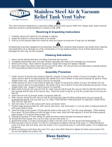 Dixon Stainless Steel Tank Vent Valve User manual
-
Armstrong GD-10 Installation And Maintenance Instructions
-
ITT Controls 3000 SERIES REGULATORS Owner's manual
-
Caleffi North America 132552A User guide
-
Dwyer Series RPV User manual
-
SWITEL WTC670 Owner's manual
-
Community R2-MAX User guide
