Zanussi ZGX9641F User manual

Category
Hobs
Type
User manual

This manual is also suitable for

Zanussi ZGX9641F is a built-in gas hob with four burners that offers a range of cooking options. It features manual, electric, or automatic electric ignition for easy lighting, and safety valves on the burners to automatically shut off the gas supply if the flame goes out. The enamelled surfaces are easy to clean and maintain, and the hob comes with a range of safety features to ensure safe operation.

Zanussi ZGX9641F is a built-in gas hob with four burners that offers a range of cooking options. It features manual, electric, or automatic electric ignition for easy lighting, and safety valves on the burners to automatically shut off the gas supply if the flame goes out. The enamelled surfaces are easy to clean and maintain, and the hob comes with a range of safety features to ensure safe operation.

Tipolitografia Montagnani - Modena - Cod. 532888 202
GB
INSTRUCTIONS BOOKLET
FOR BUILT-IN HOB
MOD.
ENVIRONMENT PROTECTION
Packing disposal
Sort packing into different materials (cardboard, polystyrene
etc.) and dispose of them in accordance with local waste
disposal laws.
This appliance must only be used for the purpose of domestic
cooking.
GB
3
GB
10
WORK-TOP USE
USING GAS BURNERS
The following symbols are on the control panel next to each knob:
- Black circle gas off
- Large flame maximum setting
- Small flame minimum setting
The minimum position is at the end of the anti-clockwise rotation
of the knob. All operation positions must be chosen between the
positions of max. and min., never choose them between max. and
off.
MANUAL IGNITION
To turn on a burner, approach a match to it, press the knob
corresponding to the selected burner and turn it anticlock-wise to
the maximum position.
ELECTRIC IGNITION (Optional)
To turn on a burner, press the knob corresponding to the selected
burner and turn it anticlockwise to the maximum position;
simultaneously pressing the electric ignition button on the control
panel marked with .
In case there is no electric current, the burner can also be lighted
using a match.
AUTOMATIC ELECTRIC IGNITION (Optional)
To turn on a burner, press the knob corresponding to the selected
burner and turn it anticlockwise to the maximum position. Keeping
the knob pressed, the electric automatic ignition of the burner will
be started up. In case there is no electric current, the burner can
also be lighted using a match.
APPLIANCES WITH SAFETY VALVE
Follow the same procedure described above to ignite the burners.
In this case, however, once you have turned the knob to the open
setting, hold it pressed in for 10 seconds. If for any reason the
burner flame goes out, the safety valve automatically shuts off the
gas supply to the burner in question.
ENERGY SAVING TIPS
. The diameter of the pan bottom should be the same as that
of the burner. The burner flame must never come out from the
pans diameter.
. Use flat-bottomed pans only.
. Whenever possible, keep a lid on the pan while cooking.
You will not need as much heat.
. Cook vegetables, potatoes, etc. with as little water as possible
to reduce cooking times.
Max
Min
Max
Min
GENERAL INFORMATION DESTINED
TO THE END USER
FIRST PART
THIS APPLIANCE HAS BEEN CONSTRUCTED AND
DISTRIBUTED IN COMPLIANCE WITH:
- The safety requirements of Directive 73/23/EEC
regarding “Low Voltages”.
- The requirements of Directive 89/336/EEC
regarding “Electromagnetic Compatibility”.
- The safety requirements of Directive 90/396/EEC
regarding “Gas Appliances”.
- Directive 89/109/EEC
regarding “Materials that can touch food”
- Moreover the above mentioned Directives comply with Directive
93/68/EEC.
This cooker is of type “X” with regard to protection against over
heating of surraounding surfaces.
DEAR CUSTOMER,
. Carefully read these instructions before using the appliance and
keep them for future consultation.
. Keep potentially hazardous packaging (plastic bags, polystyrene
etc.) out of the reach of children.
WARRANTY
Your new appliance is covered by a warranty.
The warranty certificate is herewith enclosed. If it is missing, ask
the retailer for it indicating purchasing date, model, and data plate
number which are printed on the data nameplate identifing the
appliance. Keep the smallest part of the certificate, and in case
of necessity, show it to the Technical Service together with the
receipt or the delivery bill. If you do not follow this procedure, the
technical service will be compelled to charge you with all the fees
of each eventual reparation.
AFTER SALES SERVICE
The excellent quality and advanced technology of our appliances
guarantee their perfect operation.
If, however, a fault occurs, try and remedy it by checking if you
have correctly followed all the instructions indicated in this
instructions booklet.
If, after consulting these instructions and checking the gas and
electrical connections, the fault persists, contact our After Sales
Service for prompt technical assistance.
The diameter of the
recommended pans is:
RAPID from 20 to 24 cm
SEMIRAPID from 18 to 20 cm
AUXILIARY from 12 to 18 cm
APPLIANCE MAINTENANCE
A) On the lower plate of the hob, on the outside there are some
visible screws fixing the burners and the gas manifolds to the
chassis or some screw-nuts fixing the electrical plates for all
electric or combined versions.
Once these screws or screw-nuts are unscrewed, it is possible
to replace the components inside the hob (see picture below).
GREASING OF TAPS
If a tap becomes hard to be turned, grease it using a specific
grease withstanding high temperatures.
Act as follows:
- Switch the appliance off and close the gas tap.
- Remove knobs, grids, burners and flame-spreaders.
- Follow the indications od point A and B.
- Unscrew the two fixing screws V from the burner body A (see
picture) and remove the cone C.
B)The hob is fixed in its upper part to the burners by means of
some visible screws. If these screws and the nut blocking the
taps to the hob are screwed, it is possible to open the appliance
and to reach the inside components (see picture below).
- Clean the cone C and its slot by means of a cloth soaked with
diluent.
- Slightly grease the cone with the relevant grease, put it in its
slot, and turn it some times.
- Remove the cone again, remove the exceeding grease making
sure the gas entries are not obstructed by grease residuals.
- Assemble everything carefully in the opposite direction.
TAPS REPLACEMENT
Act as follows:
- Switch the appliance off, and close the general gas tap.
- Remove knobs, grids, burners and flame-spreaders.
- Disassemble the upper hob as previously described.
- Follow the indications written in paragraphs A and B.
- Unscrew nut L of the gas tube to the burner and disassemble
the gas manifold from the hob lower plate.
- Unscrew screws R fixing the tap to the bridle and remove the
last (see picture).
Note: Every time the tap is replaced, it is necessary to replace
seal gasket D too (see picture).
Once you have finished this procedure, re-assemble
everything in the opposite sense, having care to check with
water and soap the gas circuit seal.
WARNINGS
Before performing any repair or operation, switch the appliance
off and close the gas tap.
The manufacturer declines all responsibility for any damage to
persons, animals or things caused by failure to observe the rules
indicated above.
In case it is necessary to repair or replace the inside components,
act as follows:
DISASSEMBLE OF WORK-TOP
- disconnect the electrical supply cable
- disconnect the gas supply tube
- remove the grids
- remove burners and flame-spreaders
- remove the knobs from the facia-panel
- disassemble the work-top from the cabinet unscrewing screws
Z blocking locking bridles Y (see paragraph “Assemblage and
installation of the appliance”.
Remove the hob from the top.
NO
NO
Y
Z
- Unscrew the screw " A ".
- Open the door " B ".
- Unscrew cover " C ".
- Insert battery " D ".
(1x AA size battery, whit positive terminal turned in the direction
of the cover " C ").
- Remount everything by following the inverted operations.
B
A
D C
VERSION WiTH BATTERY IGNITION
Change of battery
V
C
A
V
A
D
L
R
17
GB
9
GB
4
BEFORE CLEANING THE APPLIANCE, DISCONNECT THE
GAS GENERAL TAP AND UNPLUG APPLIANCE OR
DISCONNECT POWER AT THE MAIN CIRCUIT BREAKER OF
THE ELECTRICAL SYSTEM.
DO NOT CLEAN THE APPLIANCE SURFACES WHEN STILL
HOT.
USING ELECTRIC HOTPLATES
When using an electric hotplate for the first time or after a long
period of disuse, turn the knob to 1 and let it heat for for about 20
minutes to eliminate any possible moisture absorbed by the internal
insulating material.
- Dry the bottom of the pan before placing it on the hotplate.
- Turn the hotplate on only after placing the pan on it.
The hotplates are controlled by a 7-positions knob (from “1” to
“6”). Turn the knob anti-clockwise to the desired setting. A warning
light on the control panel will inform you if the plate is on or off.
0
6
5
4
3
2
1
0
1
2
3
4
5
6
ENERGY SAVING TIPS
. The diameter of the saucepan must be the same or slightly
larger than that of the electric hotplate. Never use a pan which
is smaller than the electric hotplate.
. Use flat-bottomed pans only.
. Preferably cover pans with a lid to permit cooking at a lower
heat.
. Always cook vegetables and potatoes, etc. in as little water to
reduce cooking times.
ATTENTION:
- Before using the appliance, do not forget to remove the plastic
films protecting some parts of the appliance (facia-panel, parts
in stainless steel, etc.).
- When the appliance is not in use, we recommend to disconnect
the current and to close the gas general tap.
- Do not use the appliance as a space heater.
IF YOU SMELL GAS:
. Open the window
. Do not touch electrical switches
. Extinguish any open flame
. Never use a flame to locate a leak, but soapy water only.
IN CASE OF FIRE:
. In case of fire, close immediately the main valve of the gas pipe
line, disconnect current and never pour water on firing oil in any
case.
. Do not store flammable products or aerosol containers near
the burners, and do not vaporize them near lighted burners.
ENAMELLED SURFACES
Clean with a damp sponge using soap and water.
Grease can be easily removed using hot water or a specific
cleansing agents for enamelled surfaces.
Do not use abrasive cleansers.
Do not leave any acid or alkaline substances (lemon juice, vinegar,
salt, etc.) on the enamel.
Clean the parts in stainless steel with specific cleansers for
stainless steel surfaces.
These detergents must be applied using a soft cloth.
Never use cleaners containing acids or chlorine.
GRIDS AND BURNERS
To clean the burners, remove them by pulling upwards and soak
them for about 10 minutes in hot water with a little detergent. After
having cleaned and washed them, wipe them carefully.
Make sure that no burner holes is clogged.
Clean the burners once a week or more frequently if necessary.
MAKE SURE YOU HAVE ASSEMBLED THE BURNERS IN A
RIGHT WAY.
ELECTRIC HOTPLATES
After use, for a good conservation, the hotplate must be slighty
greased by means of a cloth soaked with oil, so that the surface
remains always clean and bright.
This avoid the eventual formation of rust too.
IMPORTANT
Periodically check the external gas connection hose and
replace it when it shows any sign of deterioration,
Do not attempt to repair the gas hose under any
cincumstances.
Assemble burners and flame-spreaders, making sure they are
placed in the correct way on the burner body placed on the work-
top.
ELECTRICAL ADJUSTEMENT
A
B
C
- Move the connection U bolts depending on the type of supply
(see table below).
- Connect the supply cable of appropriate section (see table)
- Push the back panel back being careful to lock the cable in the
panel clamping screw.
Appliance Single-phase Three-phase connection
type connection 230V~ 400V 2N~ 400V 3N~
230V 3~
4 plates Gomma H05 RR-F Gomma H05 RR-F Gomma H05 RR-F
Section 3 x 2,5 mm
2
(*) 4 x 1,5 mm
2
(*) 5 x 1,5 mm
2
(*)
N.B.: Keeping into consideration the simultaneity coefficient of 0,75.
Suggested settings (guide):
Position Heat Use
intensity
0 Off
1 Very For melting butter, chocolate, etc. For heating small
slow amounts of liquid.
2 Low For heating larger amounts of liquid. For preparing
slow-cooking creams and sauces.
3 Medium- For thawing frozen foods and cooking stews, cooking
low at boiling or lower temperatures
4 Medium For boiling foods, roasting delicate meats and fish.
5 High For braising chops and steaks, for large meat soups.
6 Very high For boiling large amounts of water and frying.
CARE AND MAINTENANCE
GENERAL RECOMMANDATIONS
AND PRECAUTIONS
N.B.: Values for town gas injectors are valid for extra european
countries only.
GAS ADJUSTEMENT
MINIMUM FLOW ADJUSTMENT FOR HOB TAPS
In order to adjust the minimum flow of the work-top taps, act as
follows:
- Switch the burner on, and turn the knob towards the minimum
flow position (small flame)
- Remove the knob from the tap
- Introduce a little screwdriver in the tap rod (see picture).
Attention: in taps with security valve, the minimum adjusting screw
(A) is placed outside the rod tap.
A
- Unscrew the adjusting screw in order to increase the flow or
screw it to decrease the flow.
The right adjustment is obtained when the flame has a length
of about 3 or 4 mm.
- For butane/propane gas, the adjusting screw must be tight
screwed.
- Make sure that the flame does not extinguish passing quickly
from the max. flow (big flame) to the minimum flow (little flame).
- Assemble the knob again.
NOTE: Before carrying out any maintenance disconnect the
power supply.
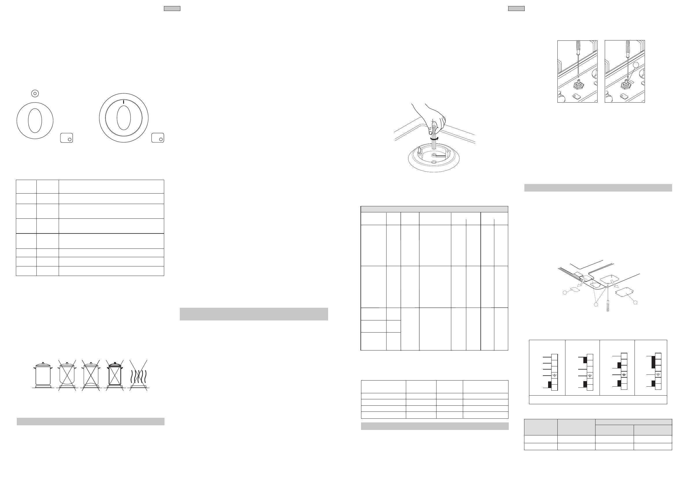
TRANSFORMATION DEPENDING ON THE TYPE OF
ELECTRICAL POWER SUPPLY.
Some models of appliances with single-phase supply can be
supplied from a three phase source by performing the following
operations:
- Remove back panel A, unscrewing screw B for all electric
versions, and C for combined versions.
E = GREEN-YELLOW / N = BLUE / L1-L2-L3 = BROWN
GENERAL INJECTORS TABLE
Kind mbar Nozzle Burners Power Watt Consum.
of gas N. max. min. max. min.
L/h
Town 145 Auxiliary 1000 300 227 68
gas 8 195 Semirapid 1650 320 375 73
G110 300 Rapid 3000 650 662 148
274 Fish burner 2600 800 591 182
345 Double crown 3500 1450 750 330
350 Triple crown 3500 1600 796 301
L/h
Natural 76 Auxiliary 1000 300 95 27
gas 20 94 Semirapid 1650 320 157 31
G20 128 Rapid 3000 650 286 62
125 Fish burner 2600 800 248 76
138 Double crown 3500 1450 315 138
140 Triple crown 3500 1600 334 143
L.P.G. g/h
gas 30 50 Auxiliary 1000 300 73 22
Butane 65 Semirapid 1650 320 120 23
G30 28 85 Rapid 3000 650 219 47
Propane 83 Fish burner 2600 800 189 58
G31 92 Double crown 3500 1450 241 106
37 97 Triple crown 3500 1600 255 109
ADJUSTMENT TO DIFFERENT TYPES OF GAS
If the appliance is foreseen to operate with a type of gas different
from the suitable supply gas, proceed as follows:
- change the injectors
- adjust the minimum flow
REPLACEMENT OF WORK-TOP INJECTORS
In order to change the work-top injectors, it is necessary to act
as follows:
- remove the grids
- remove burners and flame-spreaders
- change the injector (see picture) and replace it with another one
suitable for the new type of gas (see injectors table).
As for the built-in hobs without flame failure device, consider
the following injectors for town gas - G110 - 8 mbar
BURNERS NOZZLES POWER CONSUMPTION
N. Watts
TRIPLE CROWN 300 3500 796 L/h
RAPID 258 3000 662 L/h
S. RAPID 180 1650 374 L/h
AUXILIARY 145 1000 227 L/h
400V 3N~
(415V 3N~)
3
4
5
L1
L2
L3
1
2
E
N
230V 3~
(240V 3~)
1
2
3
4
5
E
L1
L2
L3
400V 2N~
(415V 2N~)
1
2
3
4
5
E
L1
L2
N
230V~
(240V~)
1
2
3
4
5
E
L1
N
A
B
C
E
G
H
L
M
P
Q
GB
5
GB
8
FOR YOUR SAFETY AND THE ONE OF YOUR CHILDREN.
. Do not store items that are attractive to children above or near
the appliance.
. Keep children well away from the appliance: do not forget that
some parts of the appliance or of the pans become very hot
and dangerous during use, and also for all the time necessary
to cool down.
. In order to avoid any unintentional fall down, pan handles
should be turned to the back of the cooker, not out to the room
or over adjacent burners.
. When cooking, do not use clothes with large flaving and
flammable sleeves; in case of firing you can suffer very serious
harms.
FOR APPLIANCES WITH GLASS COVER LID
While using the appliance, make sure that the glass lid does not
touch any pan. After use never close the glass lid while the
burners or the hotplates are still hot.
OVERALL DIMENSION
WORK TOP P4
MEASURES APPLIANCE
MEASURES BUILDING-IN
500
30
580
480
560
S
G
H
L
M
P
Q
A
B
E
A
B
C
D G
H
L
M
N
O
P
Q
A
R
I
L
N
O
T
F
DESCRIPTION OF THE APPLIANCE
DESCRIPTION
Work-op
Hob left grid
Rapid burner
Electric plate Ø 145
Semirapid left burner
Electric plate Ø 180 - left
Hob right grid
Semirapid right burner
Electric plate Ø 145 - right
A
B
C
D
E
F
G
H
I
Holder for mark label
Gas knob
Warning light for plate
Electric knob
Ignition button
Auxiliary burner
Electric plate Ø 180 - right
Triple crown burner
Electric palte Ø 145 - left
L
M
N
O
P
Q
R
S
T
4 GAS BURNERS WITH TRIPLE CROWN
ELECTRIC PLATES
GAS BURNERS
GAS INSTALLATION
GAS APPLIANCES
This appliance is not connected to a device to vent the combustion
products. It must therefore be installed and connected in conformity
with the installation standards in force. Particular attention must
be paid to the standards on ventilation of the room.
VENTILATION OF ROOMS
Remember that this appliance can be installed and work in well-
ventilated rooms only, according to the standards in force, such
as to allow, with openings on the external walls or with special
ducts, a correct natural or forced ventilation ensuring permanently
and sufficiently both the entry of the air needed for correct
combustion and the removal of spent air. In particular when there
is only this gas appliance in the room, there must be a hood over
the appliance to ensure the natural and direct removal of spent
air, with a vertical straight duct of length equal to at least twice the
diameter and a minimum section of at least 100 cm
2
. For the
indispensable entry of fresh air into the room there must be a
similar 100 cm
2
(5,16 cm
2
x kW) opening directly to theoutside,
situated at a height near floor level so that it is not blocked either
inside or outside the wall and so as not to cause disturbances to
correct burners combustion and to the regular removal of spent
air and with a difference of height with respect to the outlet opening
of at least 180 cm. Remember that the quantity of air necessary
for combustion must never be less than 2m
3
/h for each kW of
power (see total power in kW on the appliance data plate).
In all other cases, i.e. when there are other gas appliances in the
same room, or when natural direct ventilation is not possible and
natural indirect or forced ventilation must be installed, contact a
qualified specialist who will install and make the ventilation system,
scrupulously observing the regulations contained in the standards
in force. The openings must be so positioned that there are no
draughts of air which cannot be tolerated by the occupants.
Note: When the appliance does not have safety devices on
the hob burners (thermocouples), the ventilation openings
must be at least 100% larger with a minimum of 200 cm
2
.
GAS CONNECTION
We recommend to check wether the appliance has been foreseen
for the kind of gas distributed. The appliance must be connected
to the gas piping in a workmanlike way and in conformity with the
regulations in force which lay down the installation of a safety valve
at the end of the piping. For butane and propane a pressure
reducer conforming to the standards in force may perform this
task. The seal gaskets D must be in accordance with rules.
Once the appliance has been connected, check the connection
seal by means of soapy water.
In some appliances, the end of manifold B can be oriented
unscrewing nut C. Once found the position, carefully screw nut C
and check the seal with water and soap.
The end of the attachment is threaded.
The possible connections are:
- by rigid pipe in iron or copper;
- by flexible tube in stainless steel with continuing wall, with
mechanical connection in accordance with rules (max length
2.000 mm).
ELECTRICAL CONNECTION
Connection of the appliance to the power mains should be done
by a licensed electrician familiar with local safety regulations.
- This appliance must be earthed by law.
- Before connecting the appliance to the electrical supply,
check that the earth system in your house is working
correctly.
- Check that unit voltage and power, marked on the rating plate
applied on the appliance, are correct for the supply;
- It is necessary that the feeding network is protected by a powerful
switch able to disconnect completely the network with a contacts
separation of at least 3 mm.
Be sure that the earth wire green/yellow is not interrupted by
the switch.
Important: The wires in the mains lead are so coloured:
- green/yellow = earth “ ”
- blue = neutral “N”
- brown = live “L
The wire coloured green/yellow must be connected to the terminal
in the plug which is marked with letter ‘E’ or by the earth symbol
or coloured green or green/yellow.
The wire coloured blue must be connected to the terminal which
is marked with letter ‘N’ or coloured black. The wire coloured brown
must be connected to the terminal which is marked with letter ‘L
or coloured red.
- The supply cable must not come into contact with any component
the temperature of which exceeds the ambient temperature by
50°C;
- If a plug is used for connection, the plug to be connected to the
supply cable and the socket to which it is connected must be
of the same type (conforming to the standards).
- Easy access to the plug or the switch is ensured once the
appliance is installed;
- Ensure that there is sufficient cable allowed for any subsequent
removal of the unit.
If the plug is non-rewireable, pay attention to the following
points:
- The plug must never be cut by the supply cord. There is shock
hazard when this plug is inserted in a socket-outlet elsewhere
in the house.
- Never use the plug without the fuse cover fitted.
- Referring to the pertinent spare parts, apply to the appliance’s
supplier.
The manufacturer declines all responsibility for any damage
to persons or things caused by failure to observe the rules
indicated above.
Power supply: 230V~
B
A
D
C B
D
C B
D
TYPES OF SUPPLY CABLE
Appliance Single-phase supply 230V~
type Type of cable Section
All gas Rubber H05 RR-F 3 x 0,75 mm
2
All gas + 1 electric plate Rubber H05 RR-F 3 x 1 mm
2
All gas + 2 electric plates Rubber H05 RR-F 3 x 1,5 mm
2
4 electric plates Rubber H05 RR-F 3 x 2,5 mm
2
3 GAS BURNERS WITH 1 ELECTRIC PLATE
3
0
WARNINGS
Before performing any repair or operation, switch the
appliance off and close the gas tap.
The manufacturer declines all responsibility for any damage to
persons, animals or things caused by failure to observe the rules
indicated above.
GAS ADJUSTEMENTS
GB
7
GB
6
DESCRIPTION OF THE APPLIANCE
OVERALL DIMENSIONS
MEASURES APPLIANCE
MEASURES BUILDING-IN
INSTRUCTIONS DESTINED
TO THE INSTALLER
SECOND PART
ASSEMBLAGE AND INSTALLATION OF THE APPLIANCE
This appliance has to be placed in a top with height from 30 mm
to 40 mm.
1) Proceed to the cut of the top in accordance with the measures
indicated in the general descriptions of the appliance dimensions.
2) Set sealing strip X between cooking table and top.
3) Insert the cooking table in the top and fix it by means of fixing
clamps Y, screwing of some turns screw Z (see picture below).
4) When the appliance is installed so that its lower part can be
touched, we recommend to place a protecting wall. This
protection, withstanding high temperatures, must be placed at
least 20 mm. from the lower part of the appliance.
WARNINGS
Before performing any repair or operation, switch the appliance
off and close the gas tap. The qualified engineer is responsible
for correct installation according to the safety standards in
force.
The earthing of the appliance is legally binding. The manufacturer
declines all responsibility for any damage to persons, animals or
things caused by failure to observe the above mentioned rules.
The technical data are indicated on the data nameplate placed
on the rear of the appliance.
The adjustment conditions are stated on the label applied on the
packaging and on the appliance.
Keep the injectors provided; they could be necessary to adjust
the appliance with a different gas.
INSTALLATION
IMPORTANT: The coating of the forniture must be able to withstand
high temperatures (min. 90°C).
This appliance belongs to class X against fire dangers.
This means that the appliance can not be installed near cabinet,
whose height is higher than the appliance work top.
Note: For all appliances with triple crown burner placed on the
left side of the hob, it is necessary than the left wall of the forniture
is at least 100 mm from the hob end.
In case that units are above the appliance, these must be placed
at a minimum distance of 800 mm from the appliance top.
ASSEMBLING OF THE GLASS LID ON THE HOB
Remove stoppers P from the holes in the rear part of the hob.
Place lateral upper support T, and fix everything by means of the
two screws V.
The same procedure must be followed for the other lateral upper
support T.
For the assembling of the lid, introduce it into the relevant slots
on the two lateral upper supports T.
Z Y
X
V
C
T
P
480
840
500
30
8
6
0
M
N
A
B
Q
R
H
K
L
D
E
HOB P6
4 GAS BURNERS WITH TRIPLE CROWN BURNER
5 GAS BURNERS WITH LONG "FISH" BURNER
5 GAS BURNERS WITH TRIPLE CROWN BURNER
3 GAS BURNERS WITH TRIPLE CROWN BURNER
4 GAS BURNERS WITH AN ELECTRIC PLATE
DESCRIPTION
A Work-top
B Left grid for hob
C Rapid burner
D Triple crown burner
E Semirapid left burner
F Central grid for fish burner
G Central grid for triple crown burner
H Central grid
I Fish burner
J Electric plate Ø 145
K Semirapid right burner
L Right grid for hob
M Holder for mark label
N Gas knob
O Warning light for plate
P Electric knob
Q Ignition button
R Auxiliary burner
S Triple crown burner
T Control grid
4 GAS BURNERS
E
K
L
H
R
Q
A
B
M
N
C
20
M
N
A
B
Q
R
C
E
F
K
L
I
M
N
A
B
Q
R
C
E
G
K
L
S
M
N
A
Q
R
H
K
L
S
G
M
N
A
B
Q
R
C
E
J
K
L
O
P
T
  • Page 1 1
  • Page 2 2
  • Page 3 3
  • Page 4 4
  • Page 5 5
  • Page 6 6

Zanussi ZGX9641F User manual

Category
Hobs
Type
User manual
This manual is also suitable for

Zanussi ZGX9641F is a built-in gas hob with four burners that offers a range of cooking options. It features manual, electric, or automatic electric ignition for easy lighting, and safety valves on the burners to automatically shut off the gas supply if the flame goes out. The enamelled surfaces are easy to clean and maintain, and the hob comes with a range of safety features to ensure safe operation.

Ask a question and I''ll find the answer in the document

Finding information in a document is now easier with AI