Page is loading ...

GEH-5820C
Powr•Spot
®
Floodlight
INSTRUCTIONS
GENERAL
This luminaire is designed for outdoor lighting service, and should not be used in
areas of limited ventilation, or in high ambient temperature enclosures. Best results will
be obtained if installed and maintained according to the following recommendations.
UNPACKING
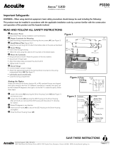
The system consists of three components; ballast, optical reector (with and
without a heavy-duty optical cover) and glass lens. If luminaire is ordered with a
PSFA (See Figure 1A) prex glass lens is shipped in same carton as optical reector.
With a ULGC (See Figure 1B), PSGN (See Figure 1C), or PSGV (See Figure 1D), glass
lens will be in a third carton with glare control device in place. Component catalog
numbers for each of assemblies are shown in Table 1. Included in table are NEMA
beam descriptions for each reector catalog number. This is VERY IMPORTANT when
more than one light distribution is to be used.
Bill of lading lists component catalog numbers in addition to complete system
catalog number. Component catalog number is a prominent feature of label on
carton and is conspicuously displayed on outside of each component. Each optical
reector has label displaying a reector "ID" which consists of fth (5) and eighth (8)
alpha/numeric character from its component catalog number: xxxx"A"xx"N". This
can be seen from ground.
Check to see that you have received the correct material undamaged in transit.
INSTALLATION
WARNING
Risk of electric shock
• Turn power o before servicing
– see instructions
CAUTION
Unit will fall if not installed properly
• Follow installation instructions
FIGURE 3
PSFA
FIGURE 1A
PSGV
All 20" Reector ID's
FIGURE 1D
ULGC/ULGN/ULGV
All 20" Reector ID's
FIGURE 1B
PSGN
All 20" Reector ID's
FIGURE 1C
READ THOROUGHLY BEFORE INSTALLING
A. CROSSARM SPACING:
These dimensions should preclude physical interference between oodlights
– when visors or other external accessories are used the vertical spacing will be
greater – contact factory.
HORIZONTAL spacing between oodlights 30"
VERTICAL spacing 36" without Top Visor
VERTICAL spacing 52" with Top Visor
B. MOUNTING:
Floodlight is provided with either a straight or angled trunnion bracket for
mounting on at surfaces. Trunnion brackets have a clearance hole for a 3/4-
inch
bolt (Tighten to 80-90 Ft. Lbs.). Angled trunnion has a slot for a 3/8-inch
bolt for anti-rotate feature. Hole pattern required for 180 degrees of rotational
freedom of angled trunnion is shown in gure 3. Note that clearance hole for
3/4-inch bolt needs to be at least 1.125-inches from edge of at mounting surface
(See gure 3).
Special mounting adapters are available for other applications.
CAUTION: Drain holes are provided for normal below-horizontal aiming. Drain
hole knockouts are provided for above-horizontal aiming. Two drain hole
knockouts are on back of casting and one is on back of socket housing. (See
Figure 2) Open these three holes if the unit is to be aimed above horizontal. It
is not necessary to close normal holes hidden below cover.
C. WIRING:
Make all electrical connections in accordance with the National Electrical Code
and any applicable local code requirements.
Verify that supply voltage is correct by comparing it to nameplate.
1. Remove cover (four screws).
NOTE: Cable strain relief and seal are provided by the casting V-notch, the rubber
bushing, and the cover.
9/16-inch O.D. three-conductor AWG #14 cable is recommended.
2. Insert cable through the rubber bushing and make electrical connections.
Optical Assembly MH MH MH HPS HPS HPS
Cat. No. REFL. 1500 1000 400 1000 750 400 REFL.
XX= GP or HD DIA. NEMA NEMA NEMA NEMA NEMA NEMA ”ID’’
PSFBBxx0 20" 3X3 3X3 3X3 — 3X3 3X3 B0
PSFBCxx0 20" 4X4 4X4 3X3 — 4X4 4X4 C0
PSFBDxx0 20" 5X5 5X5 5X5 — 5X5 5X5 D0
PSFBExx0 20" 6X6 6X6 6X6 5X5 5X5 6X6 E0
PSFBAxx2 22" 2X2 2X2 1X1 — — 1X1 A2
PSFBBxx2 22" 3X3 3X3 2X2 — — 2X2 B2
ULGCBxx0 20" 3X3 3X3 — — — — B0
ULGCCxx0 20" 4X4 4X4 — — — — C0
ULGCDxx0 20" 5X5 5X5 — — — — D0
ULGCExx0 20" 6X6 6X6 — — — — E0
*PSGNBxx0 20" 3X3 3X3 — — — — B0
*PSGNCxx0 20" 4X4 4X4 — — — — C0
*PSGNDxx0 20" 5X5 5X5 — — — — D0
*PSGNExx0 20" 6X6 6X6 — — — — E0
* Glare control optics may dier from base reector
NEMA Beam spreads.
Base Reector Catalog Numbers and NEMA Beam Spreads*
TABLE 1
TOP LENS GLASS CLIP
REFLECTOR
REPOSITIONING STOP
TRUNNION BRACKET
DRAIN HOLE
KNOCK-OUTS
COVER
GP
REFLECTOR
WITH LENS
VISOR WITH
GLARE SHIELD & LENS
DRAIN HOLE
KNOCK-OUT
BALLAST
g
GE
Lighting Solutions
These instructions do not purport to cover all details or variations in equipment nor to provide for every possible contingency to be met in connection with installation, operation or maintenance.
Should further information be desired or should particular problems arise which are not covered suciently for the purchaser’s purposes, the matter should be referred to GE Lighting Solutions.
FIGURE 2

Connect ground lead to the green lead, green ground screw on housing or terminal
block provided.
IF SINGLE VOLTAGE:
All single voltage ballasts are pre-wired such that user need only connect the
supply conductors.
IF MULTIVOLT: (120/208/240/277 volts)
Connect the ballast lead with the insulated terminal to the desired voltage terminal
as indicated on the ballast terminal nameplate.
D. FINAL ASSEMBLY:
With optical open, align keyhole slots in optical assembly with mounting bolts on
ballast housing. Rotate optical clockwise 15 degrees, and tighten bolts.
CAUTION: Close hinge bracket around glass door hinge clip with pliers.
See Fig. 4B
AIMING PREPARATION
It is very important to know NEMA light distribution for each reector if more than
one light distribution is to be used. Each light distribution is assigned an aiming point
on site or a horizontal and vertical aiming vector with respect to pole or structure
on which it is located. Each light distribution may be assigned a specic location on
each pole or structure.
Matrix in Table 1 lists component catalog number for each Powr•Spot optical in
terms of reector diameter, lamp rating, NEMA beam and reector “ID’’.
GLARE CONTROL LOUVERS & VISORS
Glare control louver and visor accessories (See Figures 1B, 1C, and 1D) are supplied
pre-assembled to a 20-inch optical glass lens, installed in same manner as a plain
glass lens. If accessories are ordered to retrot an existing 20-inch PSFB optical,
then shield insert must be installed as shown in Figure 4A. Insert may be secured
by bending two tabs through center hole and around back of reector neck. Insert
should be in place on all PSGC optical assemblies (See Table 1).
TARGET AIMING
The following procedure is accomplished after the poles have been erected with
crossarms (or cages) and luminaires assembled:
1. A grid is laid out on the eld as shown on the aiming diagram that is part of
GE supplied information. The origin (x=0, y=0) is positioned at home plate for
baseball/softball or at the center of the eld for football/soccer.
2. A target, such as a pie plate, marked with each xture's XY coordinates is placed
on the eld for all xtures that are indicated by the oodlight blocks in the xture
arrangement and aiming schedule.
3. A person at the oodlight then uses the built in sighting mechanism of the luminaire
to aim each oodlight at the proper target on the ground.
4. Rotate sight bar into position; see Figure 5A.
5. Loosen degree marker/repositioning stop and trunnion clamping bolts.
6. Align the target as shown on Figure 5B.
7. Tighten trunnion clamping bolts (80-90 Ft. Lbs.) Position against the reposition
stop and secure by tightening screw.
DEGREE AIMING
The degree markings on the oodlight mounting lack the necessary precision and
should NOT be used for angle determination. In order to achieve adequate results,
extreme care must used while performing steps described below. The following
procedure is accomplished on the ground before the pole is erected:
1. The pole and crossarms must be braced so that they are both LEVEL (parallel)
with the ground.
2. Each oodlight is attached to the crossarm(s) so that the glass lens is LEVEL
(parallel) with the ground.
3. An inclinometer is positioned on the glass lens perpendicular to the crossarm.
The down angle adjustment that is indicated in the square boxes of the xture
arrangement and aiming schedule is made. The bolts that attach the trunnion to
oodlight housing are tightened.
4. The reposition stop is then aligned against its stop and secured by tightening the
screw.
5. The bolts are then loosened and the oodlight is rotated back to its original
horizontal (level) position in preparation for Left or Right adjustment. Retighten
the bolts.
6. The inclinometer is positioned on the glass lens parallel to the crossarm. The
crossarm attachment bolts are loosened, the Left or Right angle adjustment is
made, and the bolt is retightened.
7. Finally, the trunnion/xture bolts are loosened and the oodlight is rotated to its
nal vertical position (against the reposition stop). Make sure that the stop is not
bent by rapid movement during rotation. Securely tighten all bolts and screws.
MAINTENANCE
Periodic cleaning on outside of glass lens will ensure operation at maximum optical
eciency. Glass and reector (if needed) should be cleaned with soap, glass cleaner
or detergent solutions, rinsed with cold water and wiped dry.
Light output is also dependent on age of lamp. In applications where light levels
are critical, it may be desirable to replace lamps before burn out. Lamp manufacturer
can provide data showing how lamp light output decreases with use.
LAMPS
CAUTION
Risk of burn
• Allow lamp/xture to cool before handling
Use only lamps specified on nameplate. Observe lamp manufacturer's
recommendations and restrictions on lamp operation, particularly ballast type,
burning position, etc.
1. Check trunnion-mounted repositioning stop, ensuring that it is located against
stop and secured to trunnion.
2. Loosen trunnion clamp bolts, rotate luminaire to a convenient relamping position
and tighten bolts.
3. Open glass lens, unlatching top clip last.
4. Replace lamp and close glass lens, latching top rst and checking for proper
gasket sealing. Secure remaining clips.
5. Reposition luminaire and tighten clamp bolts (80-90 Ft. Lbs.) mechanism of the
luminaire to aim each oodlight at the proper target on the ground.
6. Rotate sight bar into position; see Figure 5A.
7. Loosen degree marker/repositioning stop and trunnion clamping bolts.
8. Align the target as shown on Figure 5B.
9. Tighten trunnion clamping bolts (80-90 Ft. Lbs.). Position degree marker against
stop and secure by tightening screw.
FIGURE 5A
SIGHT BAR
FIGURE 5B
TARGET
CLIP
22 INCH
OPTICAL
CLIP
SIGHT
SIGHT
20 INCH
OPTICAL
TARGET
FIGURE 4A
REFLECTOR
TABS
SHIELD INSERT
FIGURE 4B
BEND HINGE TO
RETAIN DOOR GLASS
(WHEN REQ’D)
/