Débranchez la prise électrique à déconnexion rapide du raccord
de montage et faites le raccordement électrique comme expliqué
pour le montage sur conduite.
MONTAGE EN SURFACE
Fixez la boîte de montage en surface sur la surface d’accueil en
utilisant les quatre trous de dégagement disponibles. Débranchez la
prise électrique à déconnexion rapide du raccord de montage et
faites le raccordement électrique comme expliqué pour le montage
sur conduite.
NOTE : Les filets sur le caisson de ballast compatible avec
les types de montages précédents sont lubrifiés avec du
Versalube G322L de General Electric. Appliquez un
supplément de lubrifiant du même type si nécessaire.
CAISSON DE BALLAST
Vissez le caisson de ballast sur le raccord de montage. La prise
électrique à déconnexion rapide va automatiquement se brancher
après que cinq filets aient été engagés. Continuez de visser jusqu’à ce
que le caisson soit bien serré sur le raccord de montage, puis serrez
la vis de blocage sur le bas du raccord.
INSTALLATION DE LAMPE
Une fois la lampe installée, revissez à fond l’anneau de
globe sur le caisson de ballast. Serrez la vis de blocage.
AVERTISSEMENT : LE GLOBE EST EN VERRE
TREMPÉ, ÉVITEZ LES RAYURES ET COUPS.
RÉFLECTEURS EXTERNES
Un réflecteur, s’il est utilisé, est fixé sur le bas de l’anneau
de globe avec les trois vis fournies.
S’il y a une protection de globe sur le luminaire, le
réflecteur est fixé en utilisant les mêmes vis qui maintiennent
la protection. Ces vis n’ont seulement qu’à être desserrées
pour ce montage puisque le réflecteur est pourvus d’orifices de
montage en trous de serrure.
Si un réflecteur coudé est utilisé, orientez-le en fonction
des trois vis de façon à ce que la sortie lumineuse principale
soit près de la direction voulue. Après desserrage de la vis de
blocage, l’anneau de globe peut alors être légèrement tourné
pour parfaire l’orientation du réflecteur. La vis de blocage est
ensuite resserrée.
ENTRETIEN
Il sera nécessaire à l'occasion de nettoyer l’ensemble optique pour
maintenir le niveau d'éclairage. La fréquence de ces nettoyages
dépend du niveau d'empoussièrage local et du seuil minimum de
luminosité acceptable pour l'utilisateur. Le réflecteur doit être lavé
avec une solution d'eau et de n'importe quel détergent ménager
doux et non abrasif, rincez à l'eau claire pour enlever les résidus de
nettoyant. Le vitrage peut être nettoyé avec un produit pour vitres
classique.
35-201578-6N (1/01)
Débranchez l’alimentation électrique avant de remettre une
lampe. Desserrez la vis de blocage près du bord inférieur du caisson
de ballast. Dévissez le support du globe en verre qui est fixé sur le
caisson de ballast. Pour aider à enlever l’anneau de globe, une lame
de tournevis peut être insérée dans les fentes de levier, ou l’anneau
de globe peut être desserré en tapotant légèrement sur ses nervures.
N’utilisez que le type de lampe spécifié sur la plaque
d’identification. Observez les recommandations et restrictions
du fabricant sur le fonctionnement de la lampe, en particulier
pour le type de ballast, la position d’utilisation, etc.
Des dommages peuvent se produire dans le luminaire si la lampe
est insérée quand il est encore sous tension, ou si la lampe était mal
serrée au moment de sa mise sous tension.
SERRAGE DE LAMPE : La lampe doit être insérée de façon
sûre avec un couple de serrage NEMA-EEI spécifié à 4,4 mkg (35
livre-pouce), ce qui est le mieux réalisé en serrant fortement à la
main pour mettre un couple suffisant. Le serrage doit complètement
appuyer et charger le contact central de la douille avec le culot de la
lampe.
ATTENTION
Risque de brûlure
Laissez le bloc d’ampoule refroidir
avant d'y toucher
GEH-5850
INSTRUCTIONS
POWR•GARD
®
LUMINAIRE
READ THOROUGHLY BEFORE INSTALLING
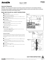
GENERAL
This luminaire is designed for application in hazardous
location environments.
INSTALLATION
WARNING
Risk of electric shock
• Turn power off before servicing
– see instructions
Make all electrical connections in accordance with
the National Electrical Code and any applicable
local code requirements.
THE OPERATING TEMPERATURE “T-CODE”
LISTED FOR THIS LUMINAIRE IS BASED ON THE
FOLLOWING BULB SIZES. USE OF OTHER THAN
THESE MAY RESULT IN A HIGHER OPERATING
TEMPERATURE AND COULD RESULT IN A HAZ-
ARDOUS CONDITION.
LAMP TYPE WATTAGE BULB SIZE
HIGH PRESSURE SODIUM 70,100,150 ED 23 1/2
HIGH PRESSURE SODIUM 250, 400 ED 18
METAL HALIDE/MERCURY 175, 250 ED 28
METAL HALIDE/MERCURY 400 ED 37
CAUTION: Check the operating temperature limits
marked on the ballast assembly prior to installa-
tion to be sure it conforms to the environmental
temperature restrictions and NEC classifications.
WARNING: TO PREVENT IGNITION OF HAZARD-
OUS ATMOSPHERES, DISCONNECT THE SUPPLY
CIRCUIT FROM THE LUMINAIRE BEFORE RELAMP-
ING, REMOVING, OR PERFORMING ANY MAINTE-
NANCE.
UNPACKING
The ballast assembly and mounting fittings have been
properly packed in separate cartons so that no parts should
have been damaged during transit. Remove packing
materials used to protect threads and inspect. Do not
attempt to assemble or use parts with damaged threads.
Verify that supply voltage is correct by comparing it
to nameplate.
CAUTION
Unit will fall if not installed properly
• Follow installation instructions
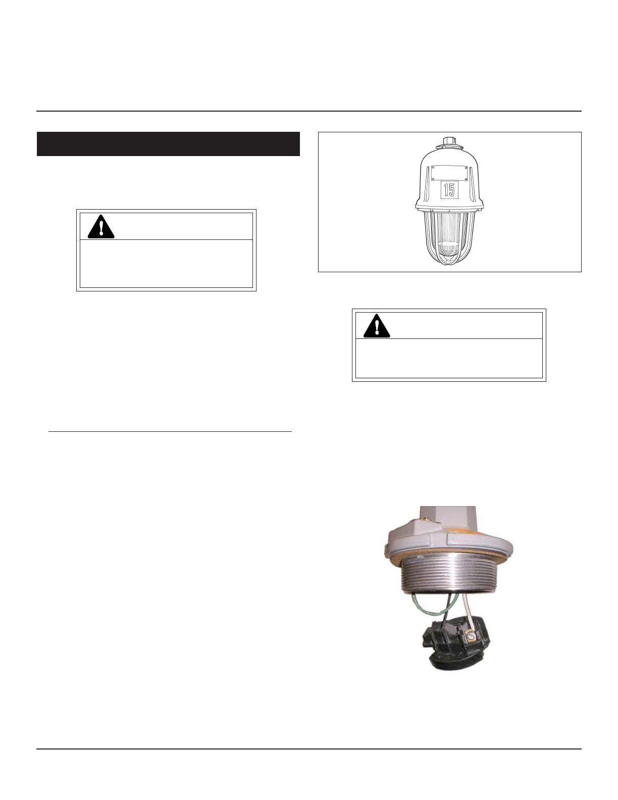
MOUNTING CONDUIT
Take the mounting hub and remove the electrical
disconnect from it. Thread the mounting hub onto the
conduit five threads minimum and tighten the set screw.
Connect the ground lead to the screw provided in the
mounting hub.
Connect the supply wires to the electrical disconnect
according to the color coding labels if applicable. Refasten
the disconnect into the mounting hub. See Figure A.
Figure A
MOUNTING STANCHION
AND WALL BRACKET
For the stanchion arm, mount arm onto the conduit five
threads minimum and tighten the set screw. For the wall
bracket, attach bracket to the support surface through the
These instructions do not purport to cover all details or variations in equipment nor to provide for every possible contingency to be met in connection with installation, operation or
maintenance. Should further information be desired or should particular problems arise which are not covered sufficiently for the purchaser’s purposes, the matter should be referred
to GE Lighting Solutions.
g
GE Lighting Solutions is a subsidiary of the General Electric Company. Evolve and other trademarks belong to GE Lighting Solutions. The GE brand and logo are trademarks of the General Electric Company.
© 2011 GE Lighting Solutions. Information provided is subject to change without notice. All values are design or typical values when measured under laboratory conditions.
GE Lighting Solutions • 1-888-MY-GE-LED • www.gelightingsolutions.com
16943533----888
g
GE
Lighting Solutions