

Printed: 08.05.2019 | Doc-Nr: PUB / 5492798 / 000 / 00


Printed: 08.05.2019 | Doc-Nr: PUB / 5492798 / 000 / 00

English 1
1 Information about the documentation
1.1 About this documentation
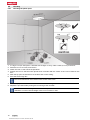
• Read this documentation before initial operation or use. This is a prerequisite for safe, trouble-free
handling and use of the product.
• Observe the safety instructions and warnings in this documentation and on the product.
• Always keep the operating instructions with the product and make sure that the operating instructions
are with the product when it is given to other persons.
1.2 Explanation of symbols used
1.2.1 Warnings
Warnings alert persons to hazards that occur when handling or using the product. The following signal words
are used:
DANGER
DANGER !
▶ Draws attention to imminent danger that will lead to serious personal injury or fatality.
WARNING
WARNING !
▶ Draws attention to a potential threat of danger that can lead to serious injury or fatality.
CAUTION
CAUTION !
▶
Draws attention to a potentially dangerous situation that could lead to slight personal injury or damage
to the equipment or other property.
1.2.2 Symbols in the documentation
The following symbols are used in this document:
Read the operating instructions before use.
Instructions for use and other useful information
Dealing with recyclable materials
Do not dispose of electric equipment and batteries as household waste
1.2.3 Symbols in the illustrations
The following symbols are used in illustrations:
These numbers refer to the corresponding illustrations found at the beginning of these operating
instructions
The numbering reflects the sequence of operations shown in the illustrations and may deviate
from the steps described in the text
Item reference numbers are used in the overview illustrations and refer to the numbers used in
the product overview section
This symbol is intended to draw special attention to certain points when handling the product.
1.3 Product-dependent symbols
1.3.1 Symbols on the product
The following symbols can be used on the product:
Printed: 08.05.2019 | Doc-Nr: PUB / 5492798 / 000 / 00

2 English
Wireless data transfer
Hilti Li-ion battery type series used. Observe the information given in the section headed In-
tended use
Pendulum locked (laser beam inclined)
Pendulum unlocked (self-leveling system active)
1.4 Product information
products are designed for professional users and only trained, authorized personnel are
permitted to operate, service and maintain the products. This personnel must be specifically informed about
the possible hazards. The product and its ancillary equipment can present hazards if used incorrectly by
untrained personnel or if used not in accordance with the intended use.
The type designation and serial number are printed on the rating plate.
▶ Write down the serial number in the table below. You will be required to state the product details when
contacting Hilti Service or your local Hilti organization to inquire about the product.
Product information
Multi-line laser PM 30-MG
Generation 01
Serial no.
1.5 Declaration of conformity
We declare, on our sole responsibility, that the product described here complies with the applicable directives
and standards. A copy of the declaration of conformity can be found at the end of this documentation.
The technical documentation is filed and stored here:
Hilti Entwicklungsgesellschaft mbH | Tool Certification | Hiltistrasse 6 | D-86916 Kaufering, Germany
2 Safety
2.1 Safety instructions
In addition to the warnings given in the various sections of these operating instructions, the following
points must be strictly observed at all times. The product and its ancillary equipment may present hazards
when used incorrectly by untrained personnel or when used not as directed.
▶ Keep all safety instructions and information for future reference.
▶ Check the accuracy of the tool before use and several times during use.
▶ Stay alert, watch what you are doing and use common sense when operating the tool. Do not use the
tool while you are tired or under the influence of drugs, alcohol or medication. A moment of inattention
while operating the tool may result in serious personal injury.
▶ Tampering with or modification of the tool is not permitted.
▶ Do not render safety devices ineffective and do not remove information and warning notices.
▶ Keep children and other persons away from the area while the tool or appliance is in use.
▶ Take the influences of the surrounding area into account. Do not use the tool where there is a risk of fire
or explosion.
▶ The laser plane should be well above or well below eye height.
▶ You must check the accuracy of the device after it has been dropped or subjected to other mechanical
stresses.
▶ To achieve maximum accuracy, project the line onto a vertical, flat surface. When doing so, set up the
tool at 90° to the surface.
▶ Keep the laser exit aperture clean to avoid measurement errors.
▶ Observe the information printed in the operating instructions concerning operation, care and maintenance.
▶ When not in use, tools must be stored in a dry, high place or locked away out of reach of children.
▶ Observe the national health and safety requirements.
Printed: 08.05.2019 | Doc-Nr: PUB / 5492798 / 000 / 00

English 3
2.2 Proper preparation of the working area
▶ Avoid awkward body positions when working from ladders. Make sure you work from a safe stance and
stay in balance at all times.
▶ Secure the site in which you are taking measurements and take care to avoid directing the beam towards
other persons or towards yourself when setting up the tool.
▶ Measurements taken through panes of glass or other objects may be inaccurate.
▶ Ensure that the tool is set up on a stable, level surface (not subject to vibration).
▶ Use the tool only within its specified limits.
▶ If several laser tools are used in the same working area, care must be taken to avoid confusing the
beams.
▶ Strong magnetic fields may affect the accuracy of the tool. Magnetic objects should thus be kept away
from the measuring tool. Hilti magnetic adapters may be used.
▶ When the tool is brought into a warm environment from very cold conditions, or vice-versa, allow it to
become acclimatized before use.
2.3 Electromagnetic compatibility
Although the device complies with the strict requirements of the applicable directives, Hilti cannot entirely
rule out the possibility of interference to the device caused by powerful electromagnetic radiation, possibly
leading to incorrect operation. Check the accuracy of the device by taking measurements by other means
when working under such conditions, or if you are unsure. Likewise, Hilti cannot rule out the possibility of
interference with other devices (e.g. aircraft navigation equipment).
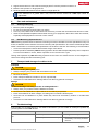
2.4 Laser classification for Class 2 laser products
The tool complies with Laser Class 2 in accordance with IEC / EN 60825-1: 2014 and in accordance with CFR
21 Sec. 1040 (FDA). These devices can be used without further protective measures. Nevertheless, as with
the sun, do not look directly into the light source. If you do inadvertently look into the laser beam, immediately
close your eyes and move your head clear of the laser beam. Do not aim the laser beam at persons.
2.5 Battery use and care
▶ Observe the special regulations and instructions applicable to the transport, storage and use of Li-ion
batteries.
▶ Do not expose batteries to high temperatures, direct sunlight or fire.
▶ Do not disassemble, crush or incinerate batteries and do not subject them to temperatures over 80 °C.
▶ Do not use or charge batteries that have suffered mechanical impact, have been dropped from a height
or show signs of damage. In this case, always contact your Hilti Service.
▶ If the battery is too hot to touch it may be defective. In this case, place the product in a non-flammable
location, well away from flammable materials, where it can be kept under observation and allowed to
cool down. In this case, always contact your Hilti Service.
Printed: 08.05.2019 | Doc-Nr: PUB / 5492798 / 000 / 00

4 English
3 Description
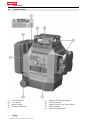
3.1 Product overview
@
Line mode button
;
Liion battery
=
Warning sticker
%
Receiver mode button
&
Battery state of charge indicator
(
Laser exit window
)
Selector switch for ON / OFF and lock /
unlock pendulum
+
Knob for fine adjustment
Printed: 08.05.2019 | Doc-Nr: PUB / 5492798 / 000 / 00

English 5
3.2 Intended use
This tool is a self-leveling multi-line laser level that allows a single person to transfer right angles, level
horizontally, carry out alignment work and plumb accurately.
The product has three green 360° laser lines, a reference point directed downward on the right-hand front
of the measuring device, as well as four beam intersection points (front, back, left, right and above) with a
range of approx. 20 m. Range depends on the brightness of ambient light.
The product is designed for mainly indoor use and is no substitute for a rotating laser. If used for outdoor
applications, care must be taken to ensure that the conditions are the same as for indoor applications. If this
is not the case, the Hilti PMA 31G laser receiver should be used.
Possible applications are:
• Marking the position of partition walls (at right angles and in the vertical plane).
• Checking and transferring right angles.
• Aligning components to be installed or sections of a structure in three axes.
• Transferring points marked on the floor to the ceiling.
The laser lines can be switched on either separately (vertical or horizontal line only) or together. When used
with inclination angle, the pendulum for self-leveling is blocked.
▶ Use only Hilti Liion batteries of the B 12 series with this product.
▶ Use only the Hilti C4/12-50 charger to charge these batteries.
3.3 Features
The product is self-leveling to within typically approx. 4.0° in all directions. Self-leveling time is about 3
seconds.
When the self-leveling range is exceeded, the laser beams blink as a warning.
When switched on, the product defaults to visibility mode with high line brightness. Horizontal and vertical
lines can be switched on and off with the line mode button. To use the PMA 31G laser receiver, activate
receiver mode by pressing the receiver mode button.
3.4 Items supplied
Multi-line laser, magnetic holder, wall-mount holder, retaining strap, case, manufacturer's certificate.
Other system products approved for use with this product can be found at your local Hilti Store or online at:
www.hilti.group.
3.5 Information displayed during operation
Status Meaning
The laser beam blinks twice every 10 seconds
(pendulum not locked) or every 2 seconds (pen-
dulum locked).
The batteries are almost exhausted.
The laser beam blinks five times and then remains
permanently on.
Activation or deactivation of receiver mode.
The laser beam blinks very rapidly. The tool cannot level itself.
The laser beam blinks every 5 seconds. Inclined line operating mode; the pendulum is
locked, so the lines are not leveled.
4 Technical data
Range of the lines and intersection point with-
out laser receiver
20 m
(65 ft - 10 in)
Range, lines and intersection point with laser
receiver
2 m … 50 m
(6 ft - 10 in … 164 ft)
Self-leveling time (typical)
3 s
Self-leveling range
±4.0° (typical)
Accuracy
± 3 mm at 10 m
(± 0.1 in at 32 ft - 10 in)
Printed: 08.05.2019 | Doc-Nr: PUB / 5492798 / 000 / 00

6 English
Line thickness
< 2.2 mm at 5 m (typical)
(< 0.09 in at 16 ft (typical))
Laser class
Class 2, visible, 510530 nm
Operating status indicator
Laser beams and the switch positions “Off”, “On
locked” and “On unlocked”
Power source
Hilti B 12 Li-ion battery
Battery life (all lines on)
Hilti B12 Li-ion battery 2600 mAh, temperature +24
°C (+72 °F): 8 h (typical)
Battery life (horizontal or vertical lines on)
Hilti B 12 Li-ion battery, 2600 mAh, temperature
+24 °C (+72 °F): 12 h (typical)
Operating temperature
−10 ℃ … 40 ℃
(14 ℉ … 104 ℉)
Storage temperature
−25 ℃ … 63 ℃
(−13 ℉ … 145 ℉)
Dust and water spray protection (except bat-
tery compartment)
IP 54
Tripod thread
BSW 5/8" | UNC 1/4"
Beam divergence
0.05 mrad * 360°
Average output power (max.)
< 0.95 mW
Weight including battery
1.28 kg
(2.82 lb)
5 Operation
CAUTION
Risk of injury! Do not direct the laser beam toward persons.
▶ Never look directly into the source of the laser beam. In the event of direct eye contact, close your eyes
and move your head out of the path of the laser beam.
5.1 Charging the battery
1. Before charging the battery, read the operating instructions for the charger.
2. Make sure that the contacts on the battery and the contacts on the charger are clean and dry.
3. Use an approved charger to charge the battery.
5.2 Inserting the battery
CAUTION
Risk of injury by short circuit or falling battery!
▶ Before inserting the battery, make sure that the contacts on the battery and the contacts on the product
are free of foreign matter.
▶ Make sure that the battery always engages correctly.
1. Charge the battery fully before using it for the first time.
2. Push the battery into the battery holder until it engages with an audible click.
3. Check that the battery is seated securely.
5.3 Removing the battery
▶ Pull the battery out of its holder in the device.
5.4 Matching two points over distance by fine adjustment
1. Position the device with the lower plumbing beam centered on the reference cross on the ground.
2. Turn the knob for fine adjustment until the vertical laser beam is aligned with the second, remote control
point.
Printed: 08.05.2019 | Doc-Nr: PUB / 5492798 / 000 / 00

English 7
5.5 Switching the laser beams on
1.
Set the selector switch to the position (ON / unlocked).
➥ The vertical laser lines are switched on.
2. Press the line mode button repeatedly until the desired line mode is set.
➥ The operating modes change in the following sequence and the sequence repeats itself: vertical lines,
vertical side line, horizontal line, vertical and horizontal lines.
5.6 Switching the laser beams off
1. Set the selector switch to the OFF position.
➥ The laser beam is switched off and the pendulum is locked.
CAUTION
Risk of injury by unintended starting!
▶ Before inserting the battery, make sure that the product is switched off.
2. The laser beam is switched off automatically when the battery is low.
5.7 Setting the laser beam for the "Inclined line" function
1.
Set the selector switch to the position (ON / locked).
2. Press the line mode button repeatedly until the desired line mode is set. → page 7
When the "Inclined line" function is active, the pendulum is locked and the laser is not leveled.
The laser beam(s) blink every 5 seconds.
5.8 Examples of applications
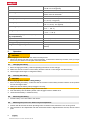
5.8.1 Transferring heights
Printed: 08.05.2019 | Doc-Nr: PUB / 5492798 / 000 / 00

8 English
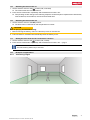
5.8.2 Setting up drywall track for a partition wall
5.8.3 Vertical alignment of pipes
Printed: 08.05.2019 | Doc-Nr: PUB / 5492798 / 000 / 00

English 9
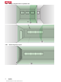
5.8.4 Aligning heating units
5.8.5 Aligning door and window frames
Printed: 08.05.2019 | Doc-Nr: PUB / 5492798 / 000 / 00

10 English
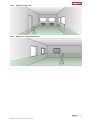
5.9 Checking
5.9.1 Checking the plumb point
1. In a high room (for example in a stairwell with a height of 10 m), make a mark (a cross) on the floor.
2. Place the tool on an even, level surface.
3. Switch the tool on and unlock the pendulum.
4. Position the tool so that the lower plumb beam coincides with the center of the cross marked on the
floor.
5. Mark the top point of intersection of the laser lines on the ceiling.
6. Pivot the tool through 90°.
The lower intersection must remain on the center of the cross.
7. Mark the top point of intersection of the laser lines on the ceiling.
8. Repeat the procedure after pivoting the tool through 180° and 270°.
Form a circle on the ceiling from the 4 marked points. Measure the diameter of the circle D in
millimeters or inches and the height of the room in meters or feet.
Printed: 08.05.2019 | Doc-Nr: PUB / 5492798 / 000 / 00

English 11
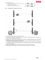
9. Calculate the value R.
➥ The value R should be less than 3 mm (corre-
sponds to 3 mm at 10 m).
➥ The value R should be less than 1/8".
5.9.2 Checking the leveling of the laser beam
1. The distance between the walls must be at least 10 m.
2. Place the tool on an even, level surface approx. 20 cm from the wall (A) with the point of intersection of
the laser lines directed toward the wall (A).
3. Mark the point of intersection of the laser lines with a cross (1) on wall (A) and with a cross (2) on wall (B).
4. Place the tool on an even, level surface approx. 20 cm from wall (B) and carefully aim the point of
intersection of the laser lines at cross (1) on wall (A).
5. Use the adjustable feet to adjust the height of the point of intersection of the laser lines so that the point
of intersection coincides exactly with the mark (2) on the wall (B). In doing so, make sure that the bubble
level remains centered.
6. Mark the point of intersection of the laser lines again with a cross (3) on the wall (A).
7. Measure the offset D between the crosses (1) and (3) on the wall (A) (RL = room length).
Printed: 08.05.2019 | Doc-Nr: PUB / 5492798 / 000 / 00

12 English
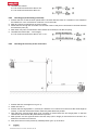
8. Calculate the value R.
➥ The value R should be less than 3 mm.
➥ The value R should be less than 1/8".
5.9.3 Checking perpendicularity (horizontal)
1. Position the tool so that the lower plumb beam coincides with the center of a reference cross marked in
the middle of a room at a distance of about 5 m from the walls.
2. Mark all 4 points of intersection on the four walls.
3. Rotate the tool through 90° and make sure that the center of the point of intersection coincides with the
first reference point (A).
4. Mark each new point of intersection and measure each offset (R1, R2, R3, R4 [mm]).
5. Calculate the offset R (RL = room length).
➥ The value R should be less than 3 mm or 1/8".
5.9.4 Checking the accuracy of the vertical line
1. Position the tool at a height of 2 m (pos.1).
2. Switch the tool on.
3. Position the first target plate T1 (vertical) at a distance of 2.5 meters from the tool at the same height (2
meters), so that the vertical laser beam strikes the plate. Mark this position.
4. Then place the second target plate T2 at a position 2 meters below the first target plate, so that the
vertical laser beam strikes the plate. Mark this position.
5. Mark position 2 at the opposite side of the test setup (mirror image) on the laser line on the floor at a
distance of 5 meters from the tool.
6. Now place the tool on the previously marked position (pos. 2) on the floor.
Printed: 08.05.2019 | Doc-Nr: PUB / 5492798 / 000 / 00

English 13
7. Align the laser beam so that it strikes the target plate T1 and the position marked on it.
8. Mark the new position on target plate T2.
9. Read the distance D between the two marks on target plate T2.
If the difference D is greater than 3 mm, the tool must be returned to a Hilti repair center for
adjustment.
6 Care and maintenance
6.1 Cleaning and drying
▶ Blow any dust off the glass.
▶ Do not touch the glass surfaces with your fingers.
▶ Use only a soft, clean cloth to clean the tool. If necessary, moisten the cloth with a little alcohol or water.
▶ Observe the specified temperature limits when storing your equipment, above all in winter and summer,
especially if the equipment is stored in a motor vehicle.
6.2 Hilti Measuring Systems Service
Hilti Measuring Systems Service checks the scanning tool and, if deviations from the specified accuracy are
found, recalibrates it and rechecks to ensure conformity with specifications. The service certificate provides
written confirmation of conformity with specifications at the time of the test. The following is recommended:
• Choose a test/inspection interval that matches usage of the device.
• Have the product checked by Hilti Measuring Systems Service after exceptionally heavy use or subjection
to unusual conditions or stress, before important work or at least once a year.
Testing and inspection by Hilti Measuring Systems Service does not relieve the user of the obligation to
check the scanning tool before and during use.
7 Transport and storage of cordless tools
Transport
CAUTION
Accidental starting during transport !
▶ Always transport your products with the batteries removed!
▶ Remove the battery.
▶ Never transport batteries in bulk form (loose, unprotected).
▶ Check the tool and batteries for damage before use after long periods of transport.
Storage
CAUTION
Accidental damage caused by defective or leaking batteries !
▶ Always store your products with the batteries removed!
▶
Store the tool and batteries in a place that is as cool and dry as possible.
▶ Never store batteries in direct sunlight, on heating units or behind a window pane.
▶ Store the tool and batteries in a place where they cannot be accessed by children or unauthorized
persons.
▶ Check the tool and batteries for damage before use after long periods of storage.
8 Troubleshooting
If the trouble you are experiencing is not listed in this table or you are unable to remedy the problem by
yourself, please contact Hilti Service.
Trouble or fault Possible cause Action to be taken
The tool can’t be switched
on.
The battery is low. ▶ Charge the battery.
The battery is not fitted correctly. ▶ Fit the battery and check that
the battery is securely seated in
the tool.
Printed: 08.05.2019 | Doc-Nr: PUB / 5492798 / 000 / 00

14 English
Trouble or fault Possible cause Action to be taken
The tool can’t be switched
on.
Device or selector switch faulty. ▶ Have the tool repaired by Hilti
Service.
Individual laser beams don’t
function.
The laser source or laser control
unit is faulty.
▶ Have the tool repaired by Hilti
Service.
The tool can be switched on
but no laser beam is visible.
The laser source or laser control
unit is faulty.
▶ Have the tool repaired by Hilti
Service.
The temperature is too high or too
low.
▶ Allow the tool to cool down or
warm up.
Automatic leveling doesn’t
work.
The tool is standing on an exces-
sively inclined surface.
▶ Set the device on a flat,
horizontal surface.
Selector switch in the position.
▶ Set the selector switch to the
position.
The inclination sensor is faulty. ▶ Have the tool repaired by Hilti
Service.
9 Disposal
Most of the materials from which Hilti tools and appliances are manufactured can be recycled. The
materials must be correctly separated before they can be recycled. In many countries, your old tools,
machines or appliances can be returned to Hilti for recycling. Ask Hilti Service or your Hilti representative
for further information.
▶ Do not dispose of power tools, electronic equipment or batteries as household waste!
10 Manufacturer’s warranty
▶ Please contact your local Hilti representative if you have questions about the warranty conditions.
11 FCC statement (applicable in US) / IC statement (applicable in Canada)
This device complies with Part 15 of the FCC Rules and CAN ICES-3 (B) / NMB-3 (B). Operation is subject
to the following two conditions:
1. This device shall cause no harmful interference.
2. This device must accept any interference received, including interference that may cause undesired
operation.
Changes or modifications not expressly approved by Hilti may restrict the user’s authorization to
operate the equipment.
Printed: 08.05.2019 | Doc-Nr: PUB / 5492798 / 000 / 00

Printed: 08.05.2019 | Doc-Nr: PUB / 5492798 / 000 / 00

Hilti = registered trademark of Hilti Corp., Schaan 20190317
Printed: 08.05.2019 | Doc-Nr: PUB / 5492798 / 000 / 00
-
 1
1
-
 2
2
-
 3
3
-
 4
4
-
 5
5
-
 6
6
-
 7
7
-
 8
8
-
 9
9
-
 10
10
-
 11
11
-
 12
12
-
 13
13
-
 14
14
-
 15
15
-
 16
16
-
 17
17
-
 18
18
-
 19
19
-
 20
20


Hilti 3622327 Operating instructions
- Category
- Laser levels
- Type
- Operating instructions
Ask a question and I''ll find the answer in the document
Finding information in a document is now easier with AI
Related papers
-
Hilti 2047037 User guide
-
Hilti PM 4-M Operating instructions
-
-
-
-
-
Hilti 411210 Owner's manual
-
-
-
Other documents
-
 Generic unbranded 0815500240 Operating instructions
-
 Futtura CL2P3 User manual
-
Bosch Power Tools GPL 3 Professional User manual
-
-
Ronix RH-9503G User manual
-
-
Bosch GSL 2 User guide
-
-
Bosch Power Tools GPL2 User manual
-
UNI-T LM570R-I User manual

