Jacobsen LMAC690-F Accessories Manual
- Category
- Lawnmowers
- Type
- Accessories Manual
This manual is also suitable for

GB
United
Kingdom
Fitting Instructions
LMAC690-F Contour Deck Field Kit
WARNING
WARNING: If incorrectly used this machine can cause severe injury. Those who use and maintain this machine
must be trained in its proper use, warned of its dangers and must read the entire manual before attempting to set
up, operate, adjust or service the machine.
25158G-GB (rev.0)
RJL 100 November 2016

1 CONTENTS
© 2016, Ransomes Jacobsen Limited. All Rights Reserved
Safety
How To Operate Safely......................................................... 3
Safe Operation ..................................................................... 3
Preparation ........................................................................... 3
Operation ............................................................................. 4
Rops ..................................................................................... 5
Safe Handling Of Fuels ........................................................ 5
Maintenance And Storage .................................................... 5
When You Put The Mower On A Trailer 6
Important Safety Notes ........................................................ 7
Fitting Instructions
Preparation ....................................................................... 10
Remove Height Of Cut Assembly ...................................... 11
Remove Anti Mohawk Assembly ....................................... 11
Remove Decks ................................................................... 12
Replace Pivot Shaft If Required ......................................... 13
Add Spacer To Wing Unit Stops (Cabbed Machine) .......... 14
Add Spacer To Wing Unit Break Back Stop ....................... 15
Mount The Contour Deck ................................................... 16
Height Of Cut Chain Set Up ............................................... 17
Wing Deck Anti Mohawk Chain Assembly ......................... 18
Front Deck Caster Wheels ................................................. 19
Height Of Cut Adjustment (Contour Wing Cutter Deck) ..... 20
Parts
Contour Deck field Fitting Kit ............................................. 22
SECTION ..............................................................PAGE

en-3
SAFETY 2
2.1 HOW TO OPERATE SAFELY ___________________________________________________
2.1.1 Safe Operation
a Read the Operator’s Manual and other training material. If the operator or technician can not read this
manual, the owner is responsible to describe this material to the operators and technicians. Manuals in
additional languages may be available on the Jacobsen or Ransomes Jacobsen website.
a Read all of the instructions for this mower carefully. Know the controls and the correct operation of the
equipment.
b Children or persons who do not understand these instructions must not use the mower. The local
regulations can limit the age of the operator.
c Never use a mower near persons, including children or animals.
d Remember that the operator or owner is responsible for accidents or hazards that occur to other persons or
their property.
e Never carry passengers.
f Never allow persons to operate or service the mower or its attachments without correct instructions.
g Do not operate equipment while tired, sick or after you use alcohol or drugs.
2.1.2 Preparation
a When you operate the mower, wear correct clothing, slip resistant work shoes or boots, work gloves, hard
hat, safety glasses and hearing protection. Long hair, loose clothing or jewelry can be caught in moving
parts.
b Do not operate the equipment with the Interlock System disconnected or the system does not operate
correctly. Do not disconnect or prevent the operation of any switch.
c Never operate equipment that is not in correct order or without decals, guards, shields, deflectors or other
protective devices fastened. When you mow with a side discharge deck, DO NOT operate the cutting unit
without the discharge chute installed.
d Inspect the mower before you operate the mower. Check the tyre pressure, engine oil level, the radiator
coolant level and the air cleaner indicator. Fuel is flammable. Use caution when you add the fuel to the
mower.
e Operate the mower in daylight or in good artificial light. Use caution when you operate the mower during
bad weather. Never operate the mower with lightning in the area.
f Inspect the area to select the accessories and attachments that are needed to correctly and safely do the
job. Only use parts, accessories and attachments approved by Manufacture.
g Be careful of holes in the terrain and other hazards that are not visible.
h Inspect the area where the equipment is operated. Remove all objects you can find before you operate. Be
careful of obstructions above the ground (low tree limbs, electrical wires) and also underground obstacles
(sprinklers, pipes, tree roots). Enter a new area carefully. Look for possible hazards.
i Inspect the cutting system before you start the mower. Make sure the blades are free to rotate. When you
rotate one blade, other blades can rotate.
WARNING
EQUIPMENT OPERATED INCORRECTLY OR WITHOUT TRAINING CAN BE DANGEROUS.
Know the location and correct operation of controls. Operators without experience must receive instruction from
another person that knows the correct operation of the equipment before you operate the mower.
Only use parts, accessories and attachments approved by Ransomes Jacobsen.
!

en-4
2 SAFETY
2.1.3 Operation
a Never operate the engine without enough ventilation or in an enclosed area. The carbon monoxide in the
exhaust fumes can increase to dangerous levels.
b Never carry passengers. Keep other persons or animals away from the mower.
c Disengage all drives and engage the parking brake before you start the engine. Only start the engine with
the operator in the seat. Never start the engine with persons near the mower.
d Keep your legs, arms and body inside the operator compartment while the mower is in operation. Keep
your hands and feet away from the cutting units.
e Do not use on the slopes greater than the safe slope limit for the equipment.
f To guard against over turning or loss of control:
– Operate the mower up and down on the face of slopes (vertically), but not across the face (horizontally).
– Do not start or stop suddenly on slopes.
– Decrease the speed when you operate on slopes or when you must turn. Use caution when you change
direction. Turf condition can change the mower stability.
– Use caution when you operate the mower near drop-offs, ditches or embankments.
– Be careful of holes in the terrain and other hazards that are not visible.
g When you drive in the reverse direction, look behind you and down to make sure the path is clear. Do not
operate the cutting units when you drive in the reverse direction.
h Use caution when you go near corners, trees or other objects that can prevent a clear view.
i Equipment must meet the current regulations to be driven on the public roads.
j Before you move across or operate on the paths or roads, turn off the PTO switch, lift the mowers and
travel at decreased speed. Look for traffic.
k Stop the blades when the mower is on any surface that is not grass.
l Do not release the cut grass in the direction of persons or allow persons near the mower while in operation.
m Do not operate the mower with damaged guards or without safety devices in position.
n Do not change the engine governor setting or over-speed the engine. Never change or tamper with
adjusters that are closed with a seal for the engine speed control.
o Before you leave the operator compartment, for any reason:
– Disengage all the drives and lower attachments to the ground.
– Engage the parking brake.
– Stop the engine and remove the key.
p When you hit an object or mower starts to cause the vibration that is not normal, inspect the mower for
damage and make repairs.
q Decrease the throttle setting before you stop the engine.
r Do not use this equipment for uses that the mower was not made for.

en-5
SAFETY 2
2.1.4 ROPS
a The ROPS is a safety device. Keep the ROPS in the vertical and locked position. Always use the seat belt
when you operate the mower. Make sure the seat belt can be released quickly in an emergency.
b The ROPS should only be folded if absolutely necessary for storage or when working on flat ground under
low obstructions. Do not operate the mower with the ROPS in the folded position on slopes, near sharp
edges or near water. There is no roll over protections with the ROPS in the folded position
c Do not operate the mower with the ROPS in the folded position on slopes, near sharp edges or near water.
There is no roll over protections with the ROPS in the folded position.
d Check for clearance before you drive below objects. Do not contact tree branches, electrical wires or other
objects with the ROPS.
e Do not use the seat belt with the ROPS in the folded position.
f Inspect the ROPS for damage. Keep the ROPS hardware fastened.
g Do not weld, drill, change or bend the ROPS. Replace a damaged ROPS. Do not try to correct a damaged
ROPS.
h Do not remove the ROPS from the mower.
i Ransomes Jacobsen must approve any changes to the ROPS.
2.1.5 Safe Handling of Fuels
a The fuel and the fuel vapors are flammable. Use caution when you add the fuel to the mower. The fuel
vapors can cause an explosion.
b Never use the containers that are not approved to keep or transfer fuel.
c Never keep the mower or fuel containers near an open flame or any device that can cause the ignition of
fuel or fuel vapors.
d Never fill the fuel containers inside a vehicle or on a truck or trailer with a plastic liner. Always put the fuel
container on the ground away from your vehicle before you fill the container.
e Refuel the mower before you start the engine. When the engine is in operation or while the engine is hot,
never remove the fuel cap or add fuel to the mower.
f Refuel outdoors only and do not smoke when you add fuel. Extinguish all types of ignition.
g The fuel nozzle must touch the rim of the fuel tank when you add fuel to the mower. Do not use a device to
lock the fuel nozzle in the open position.
h Do not over fill the fuel tank. Leave at least 1 inch (25 mm) below the filler neck.
i Always tighten the fuel tank cap and container cap after you add fuel.
j If the fuel spills on your clothing, change your clothing immediately.
2.1.6 Maintenance and Storage
a Before you clean, adjust or repair this equipment, push PTO switch to the OFF position, lower the cutting
unit to the ground, engage the parking brake, stop the engine and remove the key.
b Make sure the mower is parked on a solid and level surface.
c Never work on a mower that is lifted only by the jack. Always use the jack stands.
d Never allow persons to service the mower or its attachments without correct instructions.
e When the mower is parked, put into storage or left without an operator, lower the cutting device unless a
positive mechanical lock is used.
When you put the mower on a trailer or put the mower in storage, close the fuel valve. Do not keep fuel near
flames or drain the fuel inside a building.

en-6
2 SAFETY
f Disconnect the battery before you service the mower. Always disconnect the negative battery cable before
the positive battery cable. Always connect the positive battery cable before the negative battery cable.
g Charge the battery in an area with good airflow. The battery can release hydrogen gas that is explosive. To
prevent an explosion, keep any device that can cause sparks or flames away from the battery.
h Disconnect the battery charger from the power supply before you connect or disconnect the battery charger
to the battery. Wear protective clothing and use insulated tools when you service the battery.
i Be careful and wear gloves when you check or service the cutting unit blades. Replace any damaged
blades, do not try to correct a damaged blade.
j Keep your hands and feet away from parts that move. Do not adjust the mower with the engine in
operation, unless the adjustment needs the engine in operation.
k Carefully release the pressure from components with stored energy.
l To prevent injury from the hot, high pressure oil, never use your hands to check for oil leaks. Use the paper
or cardboard to find leaks.
m The hydraulic fluid pressure can have enough force to enter your skin. If hydraulic fluid has entered your
skin, a doctor must remove the hydraulic fluid surgically within a few hours or gangrene can occur.
n When you service the hydraulic system, make sure the hydraulic fittings, tubes and hoses are tightened to
the correct torque. Make sure the hydraulic system is in good condition before you start the engine.
o Keep the mower and the engine clean.
p Allow the engine to become cool before storage and always remove the ignition key.
q Keep all nuts, bolts and screws tight to make sure the equipment is in safe condition.
r Replace worn or damaged parts for safety. Replace damaged or worn decals. Only use parts, accessories
and attachments approved by Ransomes Jacobsen.
s To decrease the fire hazard, remove materials that burn from the engine, muffler, battery tray and fuel tank
area.
t Disconnect the battery and controller connectors before you weld on this mower.
2.1.7 When you Put the mower on a trailer
a Be careful when you load or unload the mower on a trailer. Trailer must be wider than the mower and can
carry the weight of the mower.
b Use a full-width ramp to load or unload the mower on a trailer.
c Use straps, chains, cables or ropes to fasten the mower to the trailer. Both front and rear straps must be
sent down and toward sides of trailer.
Make sure that all latches are correctly fastened.

en-7
SAFETY 2
2.1.8 Important Safety Notes
This safety alert symbol is used to alert you to possible hazards.
DANGER:
Indicates a dangerous condition that WILL cause death or injury unless it is prevented.
WARNING:
Indicates a dangerous condition that CAN cause death or injury unless it is prevented.
CAUTION:
Indicates a dangerous condition that can cause injury and property damage unless it is prevented. Also, the label
can indicate work procedures that are not safe.
IMPORTANT:
Only drive the machine at road speed when you are on a highway. You must not select road speed on grass
areas or rough roads and gravel tracks.
Some illustrations in this manual can show shields, guards or plates removed for clearness. This equipment must
not be operated without these devices correctly fastened in position.
By following all instructions in this manual, you increase the life of your machine and keep its maximum
performance. Adjustments and maintenance must always be done by an approved technician.
If additional information or service is needed. Contact your Authorized Ransomes Jacobsen Dealer, who knows
the latest methods to service this equipment and can give that service.
WARNING
The Interlock System on this mower prevents the starting of the mower unless a.) The parking brake is
Engaged. b.) The mow switch is in the OFF position, c.) The traction pedal is in the Neutral position. d) The
operator is in the seat. The system stops the engine when the operator leaves the seat a.) without the parking
brake engaged or b.) the mow switch is not in the OFF position. NEVER operate the mower unless the
Interlock System is working.
WARNING
1. Before leaving the operator’s position for any reason:
a. Return traction pedal to the Neutral position.
b. Disengage all drives.
c. Lower all implements to the ground.
d. Engage parking brake.
e. Stop the engine and remove the ignition key.
2. Keep your hands, feet, and clothing away from moving parts. Wait for all movement to stop before you
clean, adjust, or service the machine.
3. Keep the area of operation clear of all persons and animals.
4. Never carry any passengers.
5. Never operate the equipment without a correctly fastened grass deflector in position.

en-8
2 SAFETY
WARNING
California Proposition 65
Engine Exhaust, Some Of Its Constituents, And Some Vehicle Components Contain Or Release Chemicals
Known To The State Of California To Cause Cancer And Birth Defects Or Other Reproductive Harm.
WARNING
To Prevent Injury From The Hot Oil At High Pressure, Do Not Use Your Hands To Check For Oil Leaks. Make
Sure That You Use Paper Or Cardboard.
Release Of Hydraulic Fluid At High Pressure Has Enough Force To Enter Through The Skin. If The Fluid Enters
Through The Skin, The Fluid Must Be Surgically Removed Within Hours By A Specialist Doctor Or Gangrene
May Result.
WARNING
When The Machine Is Driven Off-Road, A Seat Belt Must Be Worn Only When A Rops Frame Is In Position.
This Warning Is Because A Seat Belt Must Be Worn With A Rops To Follow The Machinery Directive,
2006/42/EC Sections 3.2.2, Seating & 3.4.3, Rollover. (ANSI B71.4-2012 section 20.7)
Ransomes Jacobsen Limited Recommends That The Owner/User Of The Machine Completes A Local Risk
Assessment Of The Machine To Find Any Conditions That Do Not Follow This Rule. E.g. When You Drive The
Machine Next To Water Or On The Highway.
WARNING
Explosive Gases Are Released By Batteries. The Battery Contains Corrosive Acid And Supply An Electrical
Current That Is High Enough To Cause Burn Injuries To The Body.
WARNING
You Must Not Use This Machine To Tow Other Vehicles.
WARNING
Ear Protection Must Be Worn When You Operate Machines With
An Operator Ear Noise Level Of More Than 85 db(A) Leq.

en-9
SAFETY 2
WARNING
Vibration Exposure Limits
Exposure limits are calculated as a combination of the vibration level (magnitude) of the tool and the
Daily Exposure Time (Trigger Time). E.g. A product with 5m/s² vibration can be used up to 2 hours/day to
reach the EAV and up to 8 hours/day to reach the ELV.
Exposure Action Value (EAV) - Daily vibration exposure A(8) = 2.5m/s²
Where daily vibration exposure A(8) is below 2.5m/s² the risk is relatively low and no action need be
taken
Exposure Limit Value (ELV) - Daily Vibration Exposure A(8) = 5.0m/s²
If several tools are use the exposure values must be combined:
Total exposure is then the combined value of the activities
WARNING
Never Mow If There Is A Risk Of Lightning Or You Hear Thunder. If You Are In The Middle Of Mowing,
Stop In A Safe Place, Turn Off The Engine And Go Inside a Building.
CAUTION
When You Do Any Welding On The Machine, The Battery, Controller And Display Must Be Disconnected
Before You Start. You Must Not Open The Controller. If The Controller Is Opened, This Can Cancel All Of The
Warranties And Can Cause The Failure Of The Machine.
CAUTION
Personal Protective Equipment (PPE), For Example Safety Glasses, Leather Work Shoes Or Boots, A Hard
Hat, Leather Work Gloves And Ear Protection Must Be Used After The Owner/User Completes A Local Risk
Assessment Of The Mower, To Prevent Injury.
Training In All Manual Operations Must Be Given By An Approved Person Before The Machine Is Used The
First Time.

en-10
3 FITTING INSTRUCTIONS
3.1 PREPARATION ________________________________________________________
CAUTION: Read the safety and operation manual before you try this procedure.
1. Park the mower on a flat and level surface. Completely lower the decks to the ground. Engage
the parking brake, stop the engine and remove the key from the ignition switch.
2. Wait for all movement to stop before you make any adjustments or changes.
3. Completely inspect the equipment for any hazards.
4. Position the wheel chocks in front of wheels.
The Right and Left, Front and Rear of the machine are referenced from the operator's seat facing the
direction of forward travel.
Description
These instructions are for the installation of the LMAC690-F Contour Deck After market Field Kit.

en-11
FITTING INSTRUCTIONS 3
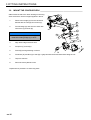
3.2 REMOVE HEIGHT OF CUT ASSEMBLY ____________________________________
1. Start the engine and lower the wing
decks, stop the engine and remove the
ignition key.
2. Remove all the components attaching
the height of cut chain to the wing deck.
3. Remove all the components attaching
the height of cut chain to the wing deck
mounting frame.
4. Repeat procedure for other wing deck.
3.3 REMOVE ANTI MOHAWK ASSEMBLY _____________________________________
1. Start the engine and lower the wing
decks, stop the engine and remove the
ignition key.
2. Remove all the components attaching
the anti Mohawk chain to the wing
deck.
3. Remove all the components attaching
the anti Mohawk chain to the wing deck
mounting frame.
4. Repeat procedure for other wing deck.
B
VIEW ‘B’

en-12
3 FITTING INSTRUCTIONS
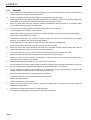
3.4 REMOVE DECKS______________________________________________________
1. Start the engine and lower the lift wing
decks, stop the engine and remove the
ignition key.
2. Disconnect the hydraulic hoses and
plug the ends.
3. Release nuts (H) and washer (G)
remove and discard.
4. Roll wing deck away from machine.
Repeat above procedure on other wing deck.
H
G
F
E
D
A
B
C

en-13
FITTING INSTRUCTIONS 3
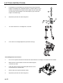
3.5 REPLACE PIVOT SHAFT IF REQUIRED ___________________________________
To improve access with the removal of the MP/HR decks, make sure there is enough space both sides of the
machine.
For older machines with Pivot Shaft without M16
tapped hole.
Removing Pivot Shaft (E)
1. Remove screw (A) and washer (B) and
discard.
2. Remove screw (C) and washer (D) and
discard.
To fit new Pivot Shaft.
1. Fit pivot shaft through wing deck frame and
lift arms. Align hole in keep plate with
threaded hole in wing deck frame.
2. Fit screw (G) and washer (H). Apply thread
lock to screw (G) and torque to 26-28 Nm.
3. Fit screw (J) and washer (K).
Repeat above procedure on other wing mounting.
A
B
C
D
E
J
K
H
G
F

en-14
3 FITTING INSTRUCTIONS
3.6 ADD SPACER TO WING UNIT STOPS (CABBED MACHINE)___________________
If spacer (B) is not already fitted.
1. Remove nut (A) and discard.
2. Fit spacer (B) to stop (C).
3. Fit spacer and stop to bracket (D)
4. Secure with new nut (A).
Repeat above procedure on other wing stop.
A
B
C
D

en-15
FITTING INSTRUCTIONS 3
3.7 ADD SPACER TO WING UNIT BREAK BACK STOP __________________________
1. Remove screw (A) and lock washer (B) and
discard.
2. Fit Spacer (D) to Stop (C). in place of
washer (E).
3. Secure with new screw (A) and lock washer
(B).
Repeat above procedure on other wing break back
stop
A
B
E
D
C

en-16
3 FITTING INSTRUCTIONS
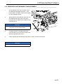
3.8 MOUNT THE CONTOUR DECK __________________________________________
Older machines that have 16mm bearings in the wing
arms will need to use the bridges supplied in the kit.
1. Remove the bridge (A) from the deck and
discard with the nuts (B) and screws (C).
2. Fit new bridge (A) and secure to deck with
new screw (C) and nut (B).
3. Align deck bridge under lift arms.
4. Fit spacer (F) to bolt (D).
5. Fit bolt (D) through bearing in lift arm.
6. Fit washer (G) and Nut (H) to bolt (D). Lightly lubricate the bolt thread before fitting the nut.
7. Torque to 205 Nm.
8. Reconnect the hydraulic hoses.
Repeat above procedure on other wing deck.
NOTE
Make sure the bolts (D) and washer (E) are
fitted before fitting bridge (A) to deck.
H
G
F
E
D
A
B
C

en-17
FITTING INSTRUCTIONS 3
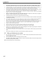
3.9 HEIGHT OF CUT CHAIN SET UP _________________________________________
Chain Bracket to Deck
1. Fit the Rear height of cut Locking Plate (9)
through the
elongated slot from the inside the deck shell.
Make sure the deck is lifted and support as
required.
2. Install the serrated plate (7) on the weld bolts,
engage in the upper end of the serrated slot.
Fasten in position with two M8 nuts (15).
3. Fit the Rear-height of cut Cover Plate (14) on
to the Rear height of cut Locking Plate (9).
4. Fit the Rear-height of cut Bracket (6) install
M8 Lockwashers (13) and fasten in position
with M8 Nuts (12).
Chain To Mounting Frame
1. Fit the Anti-vibration Washer (18) on the M16
end of height of cut Chain - Stand Off (8).
2. Assemble the height of cut Chain - Stand Off
(8) and Anti-vibration Washer (18) together.
Apply “thread lock” to the M16 threads and
screw into the Pivot Pin (A), tighten to 27Nm.
3. Fit the Rear-height of cut Plate (17) on to
height of cut Chain - Stand Off (8) fit the
Washer (3). Fasten with the M8 castellated nut
(4), make sure that the hole in item (8) is
visible for the ‘R’ Clip (1).
4. Fit the shackle (5) through the first link of the
height of cut Chain (19). Installing into the first
hole of the Rear-height of cut Plate (17).
4
NOTE
For high-height of cut range It will be necessary to rotate the Rear-height of cut Bracket (6) 180 degrees.
7
9
15
6
7
9
12
13 14 15
1
3
4
5
8
17
18
19
A

en-18
3 FITTING INSTRUCTIONS
5. Fit both Bolt (11) and Washer (16) through the first hole of the Rear
height of cut Bracket (6). Install the height of cut Chain Spacer (10) on
to Bolt (11) followed by the Chain link (19). Make sure the chain does
not pull. fit the second height of cut Chain Spacer (10) to the Rear
height of cut Bracket (6).
6. Repeat the procedure for other wing deck.
7 The chain should run in a straight line, as shown.
8. If the chain is not straight adjust the pre-tension bolt (A).
Check Wing Deck Chain Tension
1. Put a 27 mm spacer below the deck shell at the side where the new height of cut Brackets are installed.
2. Make sure the caster wheels are set to the lowest height of
cut before you start.
3. If the rear chain is slack, the serrated plate will have to be
moved lower in the serrated slot.
4. Remove the 27mm spacer below the deck.
5. Repeat the procedure for other wing deck.
A
A
A
27mm
2
6
10
11
16
19

en-19
FITTING INSTRUCTIONS 3
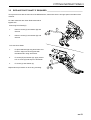
3.10 WING DECK ANTI MOHAWK CHAIN ASSEMBLY ____________________________
1. Fit Anti Mohawk chain item 3 shackle end to
Anti Mohawk Adjustable Plate item 4. Use
hole marked X as datum, make sure the plate
is in the orientation shown.
2. Attach end link of Anti Mohawk chain item 3 to
Anti Mohawk lower bracket on wing deck
using Bolt item 5, Washer item 8, Spacer item
2 and Nut item 9.
3. To adjust tautness of Anti Mohawk Chain
move shackle to one of the other holes in Anti
Mohawk adjustable Plate item 4.
4. If after adjusting the Anti Mohawk Chain item 3 is still not as taut as required,
4
NOTE
The Anti Mohawk Chain should be taut when the
wing deck is in the raised position.
NOTE
For height of cut adjustments see section 3.12.

en-20
3 FITTING INSTRUCTIONS
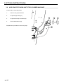
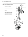
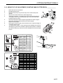
3.11 FRONT DECK CASTER WHEELS ________________________________________
It will be necessary to change the front deck caster
wheels from nine inch to eleven inch.
1. Remove both front caster wheel
assemblies.
2. Retain item (13) three off each assembly
and one item 12 from each assembly.
3. Fit new caster wheel assemblies to deck
as shown.
4. Fit caster wheel. Either pneumatic
4256572 or semi pneumatic 4336131.
5. Tighten Nut Item (10) Until A Rolling
Resistance Is Felt When spinning the
wheel. Caution Do Not Over Tighten
1
2
3
4
5
6
7
8
9
10
11
12
13
NOTE
TORQUE #6 & #9 TO 97 Nm
Page is loading ...
Page is loading ...
Page is loading ...
Page is loading ...
Page is loading ...
Page is loading ...
-
 1
1
-
 2
2
-
 3
3
-
 4
4
-
 5
5
-
 6
6
-
 7
7
-
 8
8
-
 9
9
-
 10
10
-
 11
11
-
 12
12
-
 13
13
-
 14
14
-
 15
15
-
 16
16
-
 17
17
-
 18
18
-
 19
19
-
 20
20
-
 21
21
-
 22
22
-
 23
23
-
 24
24
-
 25
25
-
 26
26


Jacobsen LMAC690-F Accessories Manual
- Category
- Lawnmowers
- Type
- Accessories Manual
- This manual is also suitable for
Ask a question and I''ll find the answer in the document
Finding information in a document is now easier with AI
Related papers
-
Ransomes 068021-E410 Owner's manual
-
-
 Jacobsen 068021-E410 Maintenance Manual
-
 Jacobsen 068021-E410 Maintenance Manual
-
-
 Jacobsen 10029628 Maintenance Manual
-
 Jacobsen 068021-E410E Maintenance Manual
-
 Jacobsen 068021-E410E Maintenance Manual
-
 Jacobsen 10029628 Maintenance Manual
-
 Jacobsen 068021-E410E Maintenance Manual


Other documents
-
-
-
-
Bretford TGLOCK User manual
-
-
-
-
-
-