Page is loading ...

LCD TELEVISION
AVC (Audio Video Control Center) & LCD Display Monitor
Operating Guide for 32HDL51
IMPORTANT SAFETY INSTRUCTIONS ................................................................................ 2-3
FIRST TIME USE .................................................................................................................. 4-26
THE REMOTE CONTROL .................................................................................................. 27-49
ON-SCREEN DISPLAY........................................................................................................ 50-77
USING THE RGB INPUT OF THE LCD TV ........................................................................ 78-87
CARE OF YOUR HITACHI LCD TV & REMOTE CONTROL .................................................. 88
RECEPTION PROBLEMS ........................................................................................................ 89
USEFUL INFORMATION/INDEX ........................................................................................ 90-98
As an ENERGY STAR
®
Partner, Hitachi, Ltd. has determined that this
product meets the ENERGY STAR
®
guidelines for energy efficiency.

2
IMPORTANT SAFETY INSTRUCTIONS
SAFETY POINTS YOU SHOULD KNOW ABOUT
YOUR HITACHI LCD TELEVISION
Our reputation has been built on the quality, performance, and ease of service of HITACHI LCD televisions.
Safety is also foremost in our minds in the design of these units. To help you operate these products properly, this
section illustrates safety tips which will be of benefit to you. Please read it carefully and apply the knowledge you
obtain from it to the proper operation of your HITACHI LCD television.
Please fill out your warranty card and mail it to HITACHI. This will enable HITACHI to notify you promptly in the
improbable event that a safety problem should be discovered in your product model.
Follow all warnings and instructions marked on this LCD television. LCD television consists of AVC center and display Monitor.
CAUTION
RISK OF ELECTRIC SHOCK
DO NOT OPEN
CAUTION: TO REDUCE THE RISK OF ELECTRIC SHOCK,
DO NOT REMOVE COVER (OR BACK).
NO USER SERVICEABLE PARTS INSIDE.
REFER SERVICING TO QUALIFIED SERVICE PERSONNEL.
The lightning flash with arrowhead symbol, within an equilateral
triangle, is intended to alert the user to the presence of uninsulated
“dangerous voltage” within the product’s enclosure that may be of a
sufficient magnitude to constitute a risk of electric shock to persons.
The exclamation point within an equilateral triangle, is intended to
alert the user to the presence of important operating and
maintenance (servicing) instructions in the literature accompanying
the appliance.
NOTE: • There are no user serviceable parts inside the AVC center/display monitor.
• Model and serial numbers are indicated on back side of the AVC center/display monitor.
POWER SOURCE
THIS
TELEVISION
IS DESIGNED TO OPERATE ON 120 VOLTS 60Hz, AC CURRENT. INSERT THE
POWER CORD INTO A 120 VOLT 60Hz OUTLET.
TO PREVENT ELECTRIC SHOCK, DO NOT USE THE TELEVISION’S (POLARIZED) PLUG WITH AN
EXTENSION CORD, RECEPTACLE, OR OTHER OUTLET UNLESS THE BLADES AND GROUND
TERMINAL CAN BE FULLY INSERTED TO PREVENT BLADE EXPOSURE.
NEVER CONNECT THE
TELEVISION
TO 50Hz, DIRECT CURRENT, OR ANYTHING OTHER THAN THE
SPECIFIED VOLTAGE.
CAUTION: Never remove the back cover of the AVC center/display monitor as this can expose you to very high
voltages and other hazards. If the television does not operate properly, unplug the LCD television and call
your authorized dealer or service center.
NOTE: This television receiver will display television closed captioning, ( or ), in accordance with
paragraph 15.119 of the FCC rules.
CAUTION:
Adjust only those controls that are covered in the instructions, as improper changes or modifications not
expressly approved by HITACHI could void the user’s authority to operate the television.
MODIFICATIONS:
The FCC requires the user to be notified that any changes or modifications made to this device that
are not expressly approved by Hitachi America, Ltd. Home Electronics Division may void the user’s
authority to operate the equipment.
WARNING: • TO REDUCE THE RISK OF FIRE OR ELECTRIC SHOCK, DO NOT EXPOSE THIS APPARATUS TO
RAIN OR MOISTURE.
• THE LCD TELEVISION SHOULD NOT BE EXPOSED TO DRIPPING OR SPLASHING AND OBJECTS
FILLED WITH LIQUIDS, SUCH AS VASES, SHOULD NOT BE PLACED ON THE TELEVISION.

IMPORTANT SAFETY INSTRUCTIONS
3
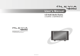
ANTENNA
LEAD IN
WIRE
ANTENNA
DISCHARGE UNIT
(NEC SECTION 810-20)
GROUNDING CONDUCTORS
(NEC SECTION 810-21)
GROUNDING CONDUCTORS
POWER SERVICE GROUNDING
ELECTRODE SYSTEM
(NEC ART 250 PART H)
NEC NATIONAL ELECTRICAL CODE
ELECTRIC
SERVICE
EQUIPMENT
GROUND
CLAMP
Read before operating equipment
Follow all warnings and instructions marked on this television.
1. Read these instructions.
2. Keep these instructions.
3. Heed all warnings.
4. Follow all instructions.
5. Do not use this apparatus near water.
6. Clean only with a dry cloth.
7. Do not block any ventilation openings. Install in accordance
with the manufacturer’s instructions.
8. Do not install near any heat sources such as radiators, heat
registers, stoves, or other apparatus (including amplifiers)
that produce heat.
9. Do not defeat the safety purpose of the polarized or
grounding-type plug. A polarized plug has two blades with
one wider than the other. A grounding type plug has two
blades and a third grounding prong. The wide blade or the
third prong are provided for your safety. If the provided plug
does not fit into your outlet, consult an electrician for
replacement of the obsolete outlet.
10. Protect the power cord from being walked on or pinched
particularly at plugs, convenience receptacles, and the point
where they exit from the apparatus.
11. Only use the attachments/accessories specified by the
manufacturer.
12. Use only with the cart, stand, tripod,
bracket, or table specified by the
manufacturer, or sold with the apparatus.
When a cart is used, use caution when
moving the cart/apparatus combination to
avoid injury from tip-over.
13. Unplug this apparatus during lightning storms or when
unused for long periods of time.
14. Refer all servicing to qualified service personnel. Servicing
is required when the apparatus has been damaged in any
way, such as power-supply cord or plug is damaged, liquid
has been spilled or objects have fallen into apparatus, the
apparatus has been exposed to rain or moisture, does not
operate normally, or has been dropped.
15. Televisions are designed to comply with the recommended
safety standards for tilt and stability.
Do not apply excessive pulling force to the front, or top, of the
cabinet which could cause the product to overturn resulting
in product damage and/or personal injury.
16. Follow instructions for wall, shelf or ceiling mounting as
recommended by the manufacturer.
17. An outdoor antenna should not be located in the vicinity of
overhead power lines or other electrical circuits.
18. If an outside antenna is connected to the receiver be sure the
antenna system is grounded so as to provide some
protection against voltage surges and built up static charges.
Section 810 of the National Electric Code, ANSI/NFPA No.
70-1984, provides information with respect to proper
grounding for the mast and supporting structure, grounding
of the lead-in wire to an antenna discharge unit, size of
grounding connectors, location of antenna-discharge unit,
connection to grounding electrodes and requirements for the
grounding electrode.
Note to the CATV system installer: This reminder is provided
to call the CATV system installer’s attention to Article 820-40
of the NEC that provides guidelines for proper grounding
and, in particular, specifies that the cable ground shall be
connected to the grounding system of the building, as close
to the point of cable entry as practical.
• This digital television is capable of receiving analog basic, digital basic and digital premium cable television programming by direct con-
nection to a cable system providing such programming. A CableCARD provided by your cable operator is required to view encrypted
digital programming. Certain advanced and interactive digital cable services such as video-on-demand, a cable operator’s enhanced
program guide and data-enhanced television services may require the use of a set-top box. For more information call your local cable
company.
• This product incorporates copyright protection technology that is protected by U.S. patents and other intellectual property rights.
Use of this copyright protection technology must be authorized by Macrovision Corporation, and is intended for home and other
limited consumer uses only unless otherwise authorized by Macrovision. Reverse engineering or disassembly is prohibited.
PUBLIC VIEWING OF COPYRIGHTED MATERIAL
Public viewing of programs broadcast by TV stations and cable companies, as well as programs from other sources, may require
prior authorization from the broadcaster or owner of the video program material.
• This product contains lead and lamps that contains mercury. Dispose of this product and its lamps in accordance
with applicable environmental laws. For lamp recycling and disposal information, go to www.lamprecycle.org. For
product recycling and disposal information, contact your local government agency or the Electronic Industries
Alliance at www.eiae.org (in the US) or the Electronic Product Stewardship Canada at www.epsc.ca (in Canada). For
more information, call “1-800-HITACHI.”
Do not place any objects on the top of the television which may fall or cause a child to climb to retrieve the objects.

ACCESSORIES
4
1. Remote Control Unit CLU-3841WL (P# HL02061) 6. Sub Woofer Cable (P# VZ11701).
or CLU-3843WL (P# HL02063). 7. Cleaning Cloth (P# MS00931).
2. Two “AA” size, 1.5V batteries (P# FQ00021).
3. Power Cord:
4. Monitor Connection Cable (P# EW07883).
5. Two IR Mouse cables (P# EY01641).
REMOTE CONTROL BATTERY INSTALLATION AND REPLACEMENT
1. Open the battery cover of the remote control by pushing the notched part of the cover with your fingers and pulling the
cover off.
2. Insert two new “AA” size batteries for the remote control. When replacing
old batteries, push them towards the springs and lift them out.
3. Match the batteries to the (+) and (-) marks in the battery compartment.
4. Replace the cover.
BOTTOM VIEW
(Remote Control)
Press down and slide back
to remove.
CAUTION: Danger of explosion if battery is incorrectly replaced. Replace with the same or equivalent type.
CAUTION: 1. Ceiling mounting is not recommended. Mounting the panel on the ceiling does not provide adequate
ventilation for the electronics or proper support for the front glass panel.
REMOTE BATTERIES POWER CORD (2)
AVC and MONITOR
MONITOR IR MOUSE
CONTROL CONNECTION CABLE CABLE (2)
3. 4. 5.
1.
7.
2.
6.
Subwoofer Cable
Cleaning Cloth
Check to make sure you have the following accessories before disposing of the packing material.
FIRST TIME USE
32”
LCD Monitor EV01841
AVC EV01841

Securing to a table-top
1. Using wood screws (two) fasten the set to the clamping screw holes on the rear of the LCD Display stand as shown below.
2. Using commercially available wood screws, secure the set firmly in position.
3. Leave some space around the unit for proper operation of the power swivel stand.
HOW TO SETUP YOUR NEW HITACHI LCD TELEVISION
5
To take measures to prevent the LCD Display from tipping over and prevent possible injury it is important to mount the unit
in a stable place.
Caution when moving the main unit
As this product is heavy, whenever it is moved, two people are required to transport it safely. Whenever the unit is moved it should be
lifted forward using the top and bottom frame on both sides of the 32” for stability, as shown below.
Securing to a wall
1. Keep the LCD Display monitor four inches away from the wall except those hung to a wall mount bracket.
2. Secure the monitor to the wall as shown below.
10cm (4 inches) or more
Wire
NOTES: 1.
Do not block the ventilation holes of the LCD Display monitor or the AVC center. Blocking the ventilation holes might cause fire
or defect.
2. The LCD television has two AC cords, one on the AVC center and the other on the LCD Display monitor. In case of an
abnormal symptom, unplug both AC cords.
ANTENNA
Unless your LCD Television is connected to a cable TV system or to a centralized
antenna system, a good outdoor color TV antenna is recommended for best performance. However, if you are located in an exceptionally
good signal area that is free from interference and multiple image ghosts, an indoor antenna may be sufficient.
LOCATION
Select an area where sunlight or bright indoor illumination will not fall directly on the picture screen. Also, be sure that the location
selected allows a free flow of air to and from the perforated back cover of the set.
To avoid cabinet warping, cabinet color changes, and increased chance of set failure, do not place the TV where temperatures can
become excessively hot, for example, in direct sunlight or near a heating appliance, etc.
When installing your LCD TV against a wall, keep it at least 10 cm (4 inches) from the wall.
32”
Wood screw
two places
32”
Handgrips
Stabilization bolts
(Provided)
String or Wire
Wood Screw
32”
FIRST TIME USE

HOW TO SET UP YOUR NEW HITACHI LCD TELEVISION
6
50
50
4" Minimum
4" Minimum
BEST
HORIZONTAL
VIEWING ANGLE
5'
10'
15'
20'
S
S
R
L
VIEWING
The major benefit of the HITACHI LCD Television is its large viewing screen. To see this large
screen at its best, test various locations in the room to find the optimum spot for viewing.
The best picture is seen by sitting directly in front of the TV and about 8 to 18 feet from the
screen.
During daylight hours, reflections from outside light may appear on the screen. If so, drapes
or screens can be used to reduce the reflection or the TV can be located in a different section
of the room.
If the TV’s audio output will be connected to a Hi-Fi system’s external speakers, the best
audio performance will be obtained by placing the speakers equidistant from each side of the
receiver cabinet and as close as possible to the height of the picture screen center. For best
stereo separation, place the external speakers at least four feet from the side of the TV, place
the surround speakers to the side or behind the viewing area. Differences in room sizes and
acoustical environments will require some experimentation with speaker placement for best
performance.
BEST
VERTICAL VIEWING
ANGLE
20
3'
0'
5'
10'
15'
20'
A buzzing sound might be heard when the LCD display monitor is turned on in a very quiet
room. This is due to the LCD panel drive circuit when it is functioning. This arching sound
is normal and it is not a malfunction.
Some infrared rays are emitted from the LCD display monitor’s panel that might affect other
infrared controlling equipment.
When receving still picture signals, (e.g. channel number indication or clock indication) for a
while, you can see image-like when the picture varied. This is not a defect.
The LCD panel is made from glass. Heavy shock on the front panel might damage it.
When the LCD monitor is transported horizontally, the glass panel has the possibility of being
broken or increasing the picture defects. At the time of transportation, horizontal style is
prohibited. More-over, please treat the LCD panel with great care because of a precision
apparatus. Please instruct transporters so that it should be put into the packing box at the time
of shipment.(There is a possibility that breakage of the panel or defects will increase.)
Rough transportation might cause damage to the panel and pixel failure.
When a screen is seen at point-blank range, a random fine grain may be visible to a dark part.
If an apparatus (VCR, etc.) antenna line is arranged near the monitor, the image may shake,
or disturbance may be received.
There is some time lag betweeen the picture and the sound. You can see lip motion that is
delayed compared to the sound.
Storing the LCD television for a period of more than 2 to 3 months without use might cause
an unstable picture when the set is turned on.
Operating altitude: 800 to 1,114hPa (6,194ft to -2,484ft). Operating temperature: 41˚F to 95˚F.
Avoid operating the LCD TV below 41˚F LCD response speed may slow down when operating
at these temperatures. This is a normal operating characteristic of the LCD monitor.
Storage Altitude: 300 to 1,114hPa (31,912ft to -2,484ft). Storage temperature: 5˚F to 140˚F.
Frequent use of the Power ON or OFF might trigger the power protection circuit. If the TV
does not turn ON, please wait a little before turning ON again.
1Arching sound from
LCD display monitor’s
panel.
2Interference for infrared
equipment.
3
Picture Image (Spectrum)
4LCD Surface
5Transportation
6 Granular spot
Black dots and Bright points may appear on the LCD screen. This is a structural property of
the LCD panel and is not a defect.
Black dots and
Bright Points
s
8
7
Disturbance to video
apparatus
9 Lip Sync
10 Caution on prolonged
storage
11 Operating
12 Storage
13 Power ON or OFF
No. Items Notes
IMPORTANT NOTES
FIRST TIME USE

HOOKUP CABLES
7
Most video/audio connections between components can be made with shielded video and audio cables that have phono connectors.
For best performance, video cables should use 75-Ohm coaxial shielded wire. Cables can be purchased from most stores that sell
audio/video products. Below are illustrations and names of common connectors. Before purchasing any cables, be sure of the output
and input connector types required by the various components and the length of each cable.
300-Ohm Twin Lead Connector
This outdoor antenna cable must be connected to an
antenna adapter (300-Ohm to 75-Ohm).
Phono Connector
Used on all standard video and audio cables which
connect to inputs and outputs located on the rear jack
panel and front control panel.
“F” Type 75-Ohm Coaxial Antenna Connector
For connecting RF signals (antenna or cable TV) to the
antenna jack on the television.
S-Video (Super Video) Connector
This connector is used on camcorders, VCRs and laser-
disc players with an S-Video feature in place of the
standard video cable to produce a high quality picture.
Monitor Connection Cable (Provided)
This cable is used to connect the Display Monitor to the
AVC Center.
AUDIO OUT
3.8mm
STEREO
MINI-PLUG
2
RCA TYPE
PLUGS
Stereo Cable (3.5 mm plug to 3.5 mm plug)
This cable is used to connect from external audio out to
the audio input of the AVC Center (ex. RGB Input).
IR Mouse Cable (Provided)
Connect the IR Mouse to the IR output on your AVC
center when A/V Network is used. You must place the
IR mouse in front of the corresponding IR window of
your cable box and VCR. This connection allows your
TV to control your cable box and VCR.
12345
678910
1112131415
D-SUB MINI 15-Pin Cable
This cable is used to connect a computer output to the
ANALOG input located on the rear panel of the AVC
Center. The resolution should be set correctly to display
the signal on the LCD Television.
Subwoofer Cable (Provided)
This cable is used to connect an external audio
component input to the subwoofer output of the Display
Monitor.
Optical Cable
This cable is used to connect to an audio amplifier with
an Optical Audio In jack. Use this cable for the best
sound quality.
D-SUB MINI 9-Pin Cable
This cable is used to connect to the RS232C input
located on the rear panel so you can control some of
your TV functions from an external home control
system.
HDMI Cable
This cable is used to connect your external devices such
as Set-Top-Boxes or DVD players equipped with an
HDMI output connection to the TV’s HDMI input.
USB Cable
This cable is used to connect your digital camera to the
Photo Input in the front of the AVC.
54321
9876
IEEE1394 Cable
This cable is used to connect your digital television to
external digital devices.This cable will carry both the
video and audio information.
FIRST TIME USE

ANTENNA CONNECTIONS TO REAR PANEL JACKS
8
VHF (75-Ohm) antenna/CATV (Cable TV)
When using a 75-Ohm coaxial cable system, connect the outdoor
antenna or CATV coaxial cable to the ANT A (75-Ohm) terminal. If you
have a second antenna, connect the coaxial cable to the ANT B
terminal.
VHF (300-Ohm) antenna/UHF antenna
When using a 300-Ohm twin lead from an outdoor antenna, connect
the VHF or UHF antenna leads to screws of the VHF or UHF adapter.
Plug the adapter into the antenna terminal on the TV.
When both VHF and UHF antennas are connected
Attach an optional antenna cable mixer to the TV antenna terminal,
and connect the cables to the antenna mixer. Consult your dealer or
service store for the antenna mixer.
To outdoor antenna
or CATV cable
To second antenna
To outdoor VHF
or UHF antenna
To outdoor antenna
or CATV system
To UHF
antenna
Antenna Mixer
ANT B
ANT B
ANT A
ANT A
FIRST TIME USE

FRONT PANEL CONTROLS
9
FRONT VIEW
a MENU/SELECT button
This button allows you to enter the MENU, making it possible to set TV features to your preference without using the remote. This
button also serves as the SELECT button when in MENU mode.
b PHOTO INPUT
Insert USB cable from your Digital Camera to view your digital still pictures (see pages 33-35).
c INPUT/EXIT button
Press this button to select the desired input, VIDEO 1 to 5, RGB, IEEE 1394, Photo Input or Ant A/B source. Your selection is shown
in the top right corner of the screen. This button also serves as the EXIT button when in MENU mode.
d CHANNEL selector
Press these buttons until the desired channel appears in the top right corner of the TV screen. These buttons also serve as
the cursor down (
H) and up (G) buttons when in MENU mode.
e VOLUME level
Press these buttons to adjust the sound level. The volume level will be displayed on the TV screen. These buttons also serve as
the cursor left (
F) and right (E) buttons when in MENU mode.
(AVC)
AUDIO VIDEO
CONTROL
CENTER
32”
DISPLAY
MONITOR
f
g
h
STANDBY (RED) ON (GREEN)
MAIN POWER
PULL
POWER
MENU/SELECT
L/(MONO) R
VIDEO
S-VIDEO
INPUT 5
PHONES
AUDIO
i
j
d
a
g
f
e
c
h
STANDBY (RED) ON (GREEN)
CH+CH-VOL+VOL- INPUT/EXIT
AUDIO VIDEO CONTROL CENTER
k
PHOTO INPUT
b
FIRST TIME USE

FRONT PANEL CONTROLS
10
f POWER button
Display Monitor “MAIN POWER” button
This power button is for the complete system, and must be turned ON/OFF manually. It is recommended to leave the “MAIN
POWER” to ON condition (lights red) for stand-by mode.
AVC POWER button
The AVC power can be turned ON/OFF manually or by remote control. Turning on the AVC Power will only turn on the AVC box if
the “MAIN POWER” of the display monitor is off.
g POWER light indicator
To turn the monitor ON, press the main power switch located on the lower right side of the monitor. A red stand-by indicator lamp
located on the lower right corner of the front bezel will illuminate. The LCD TV is now ready for remote on/off operation.
h REMOTE CONTROL sensor
Point your remote at this area when selecting channels, adjusting volume, etc.
i FRONT INPUT JACKS (for VIDEO: 5)
Use these audio/video jacks for a quick hook-up from a camcorder or VCR to instantly view your favorite show or new recording.
Press the INPUTS button then use the CURSOR PAD and the SELECT button on the remote control to select INPUT 5. VIDEO: 5
appears in the top right corner of the TV screen. If you have mono sound, insert the audio cable into the left audio jack.
j PHONES JACK
Use this jack for your head-phones. The TV’s internal speakers can also be heard. Turn off the internal speakers (see page 57) if
you wish to listen to the head-phones only.
k LEARNING AV NET Sensor
Point your equipment’s remote control at this area while using the AV NET Learning Wizard.
NOTES: 1. Your HITACHI LCD TV will appear to be turned OFF (lights orange) if there is no video input when VIDEO: 1, 2, 3,
4, 5, or RGB is selected. Check the Power Light to make sure the Display Monitor is turned off or in Stand-by
mode (lights red) when not in use.
2. Remote Control can not turn ON/OFF the “MAIN POWER” of the display monitor.
Indicating Lamp Power Status Operating
Off Off When the main power switch is set
OFF.
Lights Red Off When the main power switch on the display
(Stand-by) monitor is ON, and the AVC Center is OFF.
Lights Green On Display monitor MAIN POWER is ON and
AVC Center power is ON.
Lights Orange Off Display monitor MAIN POWER is ON and
(Power Saving) and AVC Center power is ON, with no signal
input except antenna (no sync. signal).
STANDBY (RED) ON (GREEN)
MAIN POWER
32”
or
FIRST TIME USE

REAR PANEL JACKS
11
f Component: Y-P
B
P
R
Inputs
Inputs 1 and 2 provide Y-P
B
P
R
jacks for connecting equipment with this capability, such as a DVD player or Set Top Box. You may
use composite video signal for INPUTS 1 and 2.
NOTES: 1. DO NOT connect composite VIDEO and S-VIDEO to Input 3, 4 or 5 at the same time. S-Video has a higher priority
over video input.
2. Your component outputs may be labeled Y, B-Y, and R-Y. In this case, connect the components B-Y output to the AVC
Box’s P
B
input and the components R-Y output to the AVC Box’s P
R
input.
3. Your component outputs may be labeled Y-C
B
C
R
. In this case, connect the component C
B
output to the AVC Box’s
P
B
input and the component C
R
output to the AVC Box’s P
R
input.
4. It may be necessary to adjust TINT to obtain optimum picture quality when using the Y-P
B
P
R
inputs (See page 54).
5. To ensure no copyright infringement, the MONITOR OUT output will be abnormal, when using the Y-P
B
P
R
jacks, RGB
and HDMI inputs.
a Antenna Input
The remote control allows you to switch between two separate 75-Ohm RF antenna inputs, ANT A and ANT B. ANT A input can
be displayed as a main picture or sub-picture. ANT B can only be displayed as a main picture (ANT B cannot be displayed as a
sub-picture).
b Audio/Video Inputs 1, 2, 3 and 4
By using the INPUTS button, the CURSOR PAD, and the SELECT button of the remote control, you can select each video source.
Use the audio and video inputs to connect external devices, such as VCRs, camcorders, laserdisc players, DVD players etc. (if you
have mono sound, insert the audio cable into the left audio jack).
c MONITOR OUT
These jacks provide fixed audio and video signals (ANT A/B, INPUT 1~5) which are used for recording. Use the S-VIDEO Output
for high quality video output. Component signal to Input 1 and 2, RGB and HDMI inputs will not have monitor output.
d Optical Out (Digital Audio)
This jack provides Digital Audio Output for your audio device that is Dolby
®
Digital and PCM compatible, such as an audio amplifier.
e S-VIDEO Inputs 3 and 4
Inputs 3 and 4 provide S-VIDEO (Super Video) jacks for connecting equipment with S-VIDEO output capability.
b
c
f
q
d
h
e
g
m
a
lk
ji
s
NOTES: 1. You may use VIDEO or S-VIDEO inputs to connect to INPUT 3 and 4, but only one of these inputs may be used at a
time.
2. S-VIDEO output may be used for recording, only when the input is of S-VIDEO type.
32” Monitor Bottom View
Audio Video Control Center (AVC)
FIRST TIME USE

REAR PANEL JACKS
12
g RGB - Analog Input
Use this 15-pin D-Sub input for your external devices with RGB output (see page 25).
h RGB - Audio Input
Connect audio for RGB input (if you have mono sound, insert the audio cable into the left audio jack).
i HDMI - Digital Input (INPUT 1 and INPUT 2)
About HDMI
HDMI is the next-generation all digital interface for consumer electronics. HDMI enables the secure distribution of uncompressed
high-definition video and multi-channel audio in a single cable. Because digital television (DTV) signals remain in digital format,
HDMI assures that pristine high-definition images retain the highest video quality from the source all the way to your television
screen.
Use the HDMI input for your external devices such as Set-Top-Boxes or DVD players equipped with an HDMI output connection.
HDMI, the HDMI logo and High-Definition Multimedia Interface are trademarks or registered trademarks of HDMI Licensing LLC.
j To Monitor
Connect the Monitor Connection Cable to the AVC center’s “TO MONITOR” connector, and to the display monitor’s “FROM AVC”
connector.
k IR Blaster
This jack provides IR output to your external components (VCR, Cable box, DVD player, etc.). With this connection, your external
components can automatically be controlled by the A/V network feature. This connection will allow you to control the external
components with your LCD Television’s remote control in TV mode.
l RS232C Input
For use with third party home Audio/Video control systems which are commercially available. Please see your dealer regarding
these “non Hitachi” home control systems (see page 76 to activate this input).
m IEEE1394
These jacks provide a digital interface for your external digital devices, such as a Digital VCR (D-VHS or Set-Top-Box) by means
of a single cable (see page 20). When using IEEE1394 connections, you enable video and audio digital data exchange between
a compatible device. This connection also enables you to control basic equipment functions (such as VCR play, rewind, fast
forward, stop, etc.) from your TV On-Screen Display.
n Subwoofer Out
Connect this SUB WOOFER OUT output to the external audio component input using the sub woofer cable provided.
Sub-woofer cable (RCA Type)
o To AVC
Connect the Monitor Connection cable from the AVC center’s “TO MONITOR” to these connectors (“FROM AVC”).
p SUB-POWER button
This power is for serviceman usage.
q Upgrade Card
This card slot is for future software upgrades. Hitachi will notify you if a software upgrade is required for your TV. In order to receive
written notification, please complete and return your warranty card.
r To Power Swivel Connector
Connects to the Power Swivel Table Top Stand.
Ferrite Core
NOTES: 1. The HDMI input is not intended for use with personal computers.
2. Only DTV formats such as 1080i, 720p, 480i and 480p are available for HDMI input.
FIRST TIME USE

INSERT THIS END
CableCARD
Digital Cable
REAR PANEL JACKS
13
After the CableCARD is installed, wait until the second screen below appears. The third screen below will appear if a channel is not
authorized for viewing. Press the EXIT button to exit the second screen.
Please take note of all information on the screen (you will provide this information to your cable operator). Call your cable operator
and give them the information from the card to start your cable service.
s CableCARD Slot
This slot is for the CableCARD that will be provided by your local cable operator to gain access to chosen cable channels. The
CableCARD will allow you to tune digital and high definition cable channels. Please call your local cable operator if this service is
available before requesting a CableCARD (also known as Point of Deployment (POD) module).
Connect a coaxial cable to ANT A terminal of the Rear Panel Jacks.
Insert the CableCARD into the slot (Top of card should be facing up as shown).
Rear Panel of AVC
If the CableCARD is properly installed or not installed, the TV will display the following respective screens.
CableCARD is installed CableCARD
is not installed
OR
In order to start cable service
for this device, please contact
your cable provider
CableCARD(tm): 123-456-789-1
Host: 123-456-789-1
Data: 123-456-789-1
UnitAddress: 123-456-789-1
Acquiring Data.
Please wait.
Press EXIT to return
Not an Authorized Channel
NOTES: 1. A digital cable subscription is required.
2. Antenna B will not be available when CableCARD is inserted.
3. Do not insert a PCMCIA card into the CableCARD slot.
4. Please see pages 63-64 and 76 for additional CableCARD information.
FIRST TIME USE

CONNECTING LCD DISPLAY MONITOR TO AVC BOX
14
The front panel jacks are provided as a convenience to allow you to easily connect a camcorder or VCR as shown in the following
examples:
NOTES: 1. Completely insert connection cord plugs when connecting to front panel jacks. If you do not, the played back picture
may be abnormal.
2. If you have a S-VHS VCR, use the S-INPUT cable in place of the standard video cable.
3. If you have a mono VCR, insert the audio cable into the left audio jack of your AVC box.
4. S-VIDEO input takes priority over VIDEO input.
5. If you have a VHS or 8mm camcorder, use the S-VIDEO cable in place of the VIDEO cable.
PHONES
Front panel of AVC
PHONES
L/(MONO) R
VIDEO
S-VIDEO
INPUT 5
AUDIO
Front panel of AVC
L/(MONO) R
VIDEO
S-VIDEO
INPUT 5
AUDIO
CONNECTING EXTERNAL VIDEO SOURCES
1. From the owner’s accessory you will find the Monitor Connector cable.
2. Firmly, and securely insert the Monitor Connection Cable to the rear panel of the AVC box “TO MONITOR” connectors.
3. Insert the other ends of the Monitor Connection Cable to the display monitor rear panel “FROM AVC” connectors.
Back of AVC Center
To AC
outlet
To AC
outlet
Core
AC IN
TO MONITOR
Please use HITACHI specified cable.
Back of Display Monitor
32∫
NOTE: The Display Monitor and the AVC Center have their own AC Power. Both AC cords must be completely plugged in to
the AVC Center and the display monitor, then plug them in to the AC outlets.
FIRST TIME USE

CONNECTING EXTERNAL VIDEO SOURCES
15
The exact arrangement you use to connect the VCR, camcorder, laserdisc player, DVD player, or HDTV Set Top Box to your LCD TV
is dependent on the model and features of each component. Check the owner’s manual of each component for the location of video
and audio inputs and outputs.
The following connection diagrams are offered as suggestions. However, you may need to modify them to accommodate your
particular assortment of components and features. For best performance, video and audio cables should be made from coaxial
shielded wire.
Before Operating External Video Source
Connect an external source to one of the INPUT terminals, then press the INPUTS button to show the INPUTS menu. Use the
CURSOR PAD to select the Antenna or Input of your choice. Then press the SELECT button to confirm your choice (see page 33).
Input 2
Input 1
Ant A
Ant B
Photo Input
Move
SEL
Sel.
CONNECTING A MONAURAL AUDIO SOURCE TO INPUT1~INPUT5
1. Connect the cable from the VIDEO OUT of the VCR or the laserdisc player to the INPUT (VIDEO) jack, as shown on the AVC
Center below.
2. Connect the cable from the AUDIO OUT of the VCR or the laserdisc player to the INPUT (MONO)/L(AUDIO) jack.
3. Press the INPUTS button, then select INPUT 3 from the INPUTS menu to view the program from the VCR or the laserdisc player.
The VIDEO label disappears automatically after approximately four seconds.
4. Select Ant A or B from the INPUTS menu to return to the previous channel.
VIDEO OUT
AUDIO OUT
VCR
Back of VCR
FIRST TIME USE

CONNECTING EXTERNAL VIDEO SOURCES
16
CONNECTING A STEREO VCR OR STEREO LASERDISC PLAYER
1. Connect the cable from the VIDEO OUT of the VCR or the laserdisc player to the INPUT (VIDEO) jack, as shown on the AVC
Center below.
2. Connect the cable from the AUDIO OUT R of the VCR or the laserdisc player to the INPUT (AUDIO/R) jack.
3. Connect the cable from the AUDIO OUT L of the VCR or the laserdisc player to the INPUT (AUDIO/L) jack.
4. Press the INPUTS button, then select INPUT 3 from the INPUTS menu to view the program from the VCR or laserdisc player.
The VIDEO label disappears automatically after approximately four seconds.
5. Select ANT A or B from the INPUTS menu to return to the previous channel.
Back of
VCR
R L V
VCR
OUTPUT
NOTES: 1. Completely insert the connection cord plugs when connecting to rear panel jacks. The picture and sound that is
played back will be abnormal if the connection is loose.
2. A single VCR can be used for VCR #1 and VCR #2, but note that a VCR cannot record its own video or line output
(INPUT: 4 in example on page 25). Refer to your VCR operating guide for more information on line input-output
connections.
FIRST TIME USE

17
CONNECTING EXTERNAL VIDEO SOURCES
CONNECTING S-VIDEO VCR OR LASERDISC PLAYER
1. Connect the cable from the S-VIDEO OUT of the S-VHS VCR or the laserdisc player to the INPUT (S-VIDEO) jack, as shown
on the AVC Center below.
2. Connect the cable from the AUDIO OUT R of the VCR or the laserdisc player to the INPUT (AUDIO/R) jack.
3. Connect the cable from the AUDIO OUT L of the VCR or the laserdisc player to the INPUT (AUDIO/L) jack.
4. Press the INPUTS button, then select INPUT 4 from the INPUTS menu to view the program from the VCR or laserdisc player.
The VIDEO label disappears automatically after approximately four seconds.
5. Select ANT A or B from the INPUTS menu to return to the previous channel.
NOTES: 1. Completely insert the connection cord plugs when connecting to rear panel jacks. The picture and sound that is
played back will be abnormal if the connection is loose.
2. A single VCR can be used for VCR #1 and VCR #2, but note that a VCR cannot record its own video or line output
(INPUT: 4 in example on page 25). Refer to your VCR operating guide for more information on line input-output
connections.
VCR or Laserdisc Player
OUTPUT
Back of VCR or
Laserdisc Player
R L V
S-VIDEO
FIRST TIME USE

18
CONNECTING EXTERNAL VIDEO SOURCES
CONNECTING A COMPONENT SOURCE WITH HDMI or DVI CAPABILITY TO INPUT 1 or INPUT 2
1. Connect the HDMI or DVI to HDMI connection cable from the output of the HDTV set top box or DVD player to the HDMI
input as shown on the AVC Center below.
2. With DVI output, connect the cable from the AUDIO OUT R of the HDTV set top box or DVD player to the INPUT (AUDIO/R)
jack.
3. With DVI output, connect the cable from the AUDIO OUT L of the HDTV set top box or DVD player to the INPUT (AUDIO/L)
jack.
4. Press the INPUTS button, then select INPUTS 1 or 2 to view the program from the HDTV set top box or DVD player. The VIDEO
OSD label disappears automatically after approximately four seconds.
5. Select ANT A or B from the INPUTS menu to return to the previous channel.
NOTES: 1. Completely insert the connection cord plugs when connecting to rear panel jacks. The picture and sound that is
played back will be abnormal if the connection is loose.
2. The HDMI input on INPUT 1 or 2 contains the copy protection system called High-bandwidth Digital Content
Protection (HDCP). HDCP is a cryptographic system that encrypts video signals when using HDMI connections to
prevent illegal copying of video contents.
3. HDMI is not a “NETWORK” technology. It establishes a one-way point-to-point connection for delivery of
uncompressed video to a display.
4. The connected digital output device controls the HDMI interface so proper set-up of device user settings determines
final video appearance.
D-VHS
DIGITAL OUTPUT
Back of
D-VHS
HDMI
Cable
or
LR
OUTPUT
D-VHS
DIGITAL OUTPUT
Back of
D-VHS
DVI to HDMI
Cable
or
or
P
B
P
R
HDMI input
DVI to HDMI Input
FIRST TIME USE

19
CONNECTING EXTERNAL VIDEO SOURCES
CONNECTING A STEREO LASERDISC/DVD PLAYER OR HDTV SET TOP BOX TO INPUT 1 OR 2 COMPONENT: Y-P
B
P
R
.
1. Connect the cable from the Y OUT of the Laserdisc/DVD player or HDTV set top box to the INPUT (Y) jack, as shown on the
AVC Center below.
2. Connect the cable from the C
B
/P
B
OUT or B-Y OUT of the Laserdisc/DVD player or HDTV set top box to the INPUT (P
B)
jack.
3. Connect the cable from the C
R
/P
R
OUT or R-Y OUT of the Laserdisc/DVD player or HDTV set top box to the INPUT (P
R
) jack.
4. Connect the cable from the AUDIO OUT R of the Laserdisc/DVD player or HDTV set top box to the INPUT (AUDIO/R) jack.
5. Connect the cable from the AUDIO OUT L of the Laserdisc/DVD player or HDTV set top box to the INPUT (AUDIO/L) jack.
6. Press the INPUTS button, then select INPUT 1 or 2 from the INPUTS menu to view the program from the Laserdisc/DVD player
or HDTV set top box. The VIDEO label disappears automatically after approximately four seconds.
7. Select ANT A or B to return to the previous channel.
OUTPUT
DVD Player
OR
Back of
DVD Player
OUTPUT
LRY P
B
P
R
HDTV Set-Top Box
P
R/
C
R
P
B/
C
B Y
VIDEO
L R
AUDIO
NOTE: 1. Completely insert the connection cord plugs when connecting to rear panel jacks. The picture and sound that is
played back will be abnormal if the connection is loose.
2. See page 26 for tips on REAR PANEL CONNECTIONS.
FIRST TIME USE

CONNECTING EXTERNAL VIDEO SOURCES
20
CONNECTING A COMPONENT SOURCE WITH DIGITAL INTERFACE CAPABILITY TO IEEE1394 TERMINALS
1. Connect the IEEE1394 cable from the output of the component with IEEE1394 capability, such as a Set-Top-Box or Digital VCR,
to the IEEE1394 input terminals shown on the AVC Center below. IEEE 1394 allows the LCD television and the external
device to communicate with one another. When using IEEE1394 connections, you enable video and audio digital data exchange
between a compatible device. This connection also enables you to control basic equipment functions (such as VCR play,
rewind, fast forward, stop, etc.) from your TV On-Screen Display.
2. Press the INPUTS button on the Remote Control.
3. Select the IEEE1394 option (see page 36).
IEEE1394 Cable
S-VIDEO
R
(MONO)/L VIDEO
1
DIGITAL INTERFACE
S-VIDEO
R
(MONO)/L VIDEO
2
LINE OUT
IEEE1394
Digital VCR (D-VHS)
NOTES: 1. This LCD TV’s IEEE1394 connection is not compatible with a DV camcorder (Digital Video camcorder) and a PC.
2. With IEEE1394 connection, video and audio will be received by the TV. It will enable you to control the D-VHS from
the TV IEEE1394 menu (see page 36).
3. The IEEE1394 interface contains the copy protection standard called 5C or Digital Transmission Content Protection
(DTCP).
4. See page 26 for tips on Rear Panel Connections.
FIRST TIME USE
1/100