Page is loading ...

I
n
struction Manual
English
ELMA 2000X / 2100X
VOLTAGE TESTER
1. Features
●Designed to meet international safety standards.
IEC61243-3 / 61010-1 / 61010-031 / 61557-7
Measurement Category (CAT.) IV 600V
●Self-Diagnostic test
●AC and DC voltage test up to 690V with LEDs
and LCD ( only ELMA2100X ).
●Polarity indication
●Single-pole phase test
●Phase rotation test
●Continuity test
●Auto-power ON / OFF
●Pen light for illuminating measurement points
●Selectable probe Tips 2/4mm
●CAT.III/IV caps copes with the latest European
Safety standard for 4mm tips
CAT.III 690V/ CAT.IV 600V
●Probe protection cover protects user and test tips
●IP65 (IEC60529)
●Compact design (Light weight and portable)
2. Safety Warnings
This instrument has been designed to be used by
skilled persons and in accordance with safe
methods of work, and has been designed, manu-
factured and tested according to IEC 61010/61243:
Safety requirements for Electronic Measuring
apparatus, and is supplied having passed rigorous
quality procedures.
The operating instructions contain information and
cautions required for safe operation and use of the
instrument. Before using the instrument, read the
operating instructions carefully and follow them in
all respects.
Failure to follow the instructions or to comply with
warnings and cautions may result in
life-threatening injuries to the user and damage
to the instrument and/or device under test.
WARNING is reserved for conditions and ac-
tions that are likely to cause serious or fatal injury.
CAUTION is reserved for conditions and ac-
tions that can cause injury or instrument damage.
Symbols used on the instrument
User must refer to the explanations in the
instruction manual.
Instrument with double or reinforced insu-
lation, Class II insulation.
Insulated personnel body protective
equipment up to 690V.
CAT.II
Electrical circuits of equipment connected
to an AC electrical outlet by a power cord.
CAT.III
Primary electrical circuits of the equipment
connected directly to the distribution panel
and feeders from the distribution panel to
outlets.
C
A
T.IV
Th
e circuit from the service drop to the
service entrance, and to the power meter
and primary overcurrent protection device
(distribution panel).
C
E
Co
mply with EMC and Low Voltage Di-
rective.
W
A
RNING
●Never make measurement on a circuit in
which the electrical potential exceeds 690V.
●Do not attempt to make measurement in the
presence of flammable gasses, as the use
of the instrument may cause sparking,
which could lead to an explosion.
●Never attempt to use the instrument if it’s
surface or your hands are wet.
(Do not use in rainfall.)
●Never unlock and open the Battery case
during measurements.
●Verify proper operation on a known source
before use or taking action as a result of the
indication after use.
●Never attempt to make any measurement if
any abnormal conditions, such as a broken
case or exposed metal parts are present on
the Instrument or test probes.
●Do not make any disassembly or any
modification to the instrument.
●Extreme caution when Live circuit LED
blinks or lights on.
●Correct indication of LEDs is only
guaranteed within a temperature range of
-15°C up to 55°C (<85% RH).
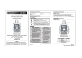
3. Instrument layout
1 12/24/50/120/230/400/690V LEDs
for voltage indication
2 Buzzer
3 L/R LEDs for phase rotation test
4 Live circuit LED for Single-pole phase and
Double-pole test
5 Rx LED for Continuity test
6 Polarity indication LEDs
7 LCD (only ELMA2100X )

4
. Preparation for measurement
4.1 Auto-power-on / Self-diagnostic test
●Auto-power-on
►Short-circuiting the probes as follows powers
on the instrument automatically and goes into a
Self-diagnostic test. If the tester is not in sleeping
mode, please wait for 10 seconds and carry out
the Self-diagnostic test.
Instrument may power on;
* when replacing Tips, or
* due to the influence of static charge.
►When the battery voltage is below 2.4±0.1V,
Rx LED blinks (and the battery symbol will also
light up as for ELMA2100X) which indicates that
the battery capacity is low.
●Self-diagnostic test
WARNING
Do not use the instrument when abnormality
is found at Self-diagnostic test.
►Battery voltage is normal when all LEDs are
lighting up and the buzzer is beeping.
►When the battery voltage is below approx. 2.6V, L
and/or R LEDs will not light up and the Phase
rotation test of Clause 6.4 will not operate.
►When the Rx LED blinks, all the functions except
for the double-pole test without batteries of Clause
6.2 will not be guaranteed.
►When the necessary functions will not operate,
please replace the batteries according to Clause 7.
●Auto-power off
►Instrument is automatically powered off after 5
sec when there is no signal contacted to the
probes.
Auto-power off may not operate;
* when replacing Tips, or
* when a significant electric magnetic field exists
in the vicinity.
5. Handy construction
Diameter and length (adapter cap) of the Tips
are changeable by user.
W
ARNING
Remove the probes from the measurement
point when replacing Tips or Caps.
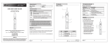
5.1 Tip Replacement
►Following shows how to install 4mm Tips on
L1 probe – and L2 probe +.
►Firmly tighten up the 4mm Tips.
5.2 CAT.III/IV Cap Replacement
►Following shows how to install the CAT.III/IV cap
on L1 probe – and L2 probe +.
►Gently put the CAT.III/IV cap onto the probes.
►Do not install the CAT.III/IV cap when the 4mm
Tips is installed.
6. Measurement
W
ARNING
●Carefully check Clause 2 as well.
●Self-diagnostic test should be done prior to
measurements and confirm LED and
buzzer works properly.
●Verify proper operation on a known source
before and after use even if the
Self-diagnostic test is OK.
●Make sure that you can hear the buzzer at
locations with a high background noise.
●Keep your hand and fingers behind the
Finger guards on the probes during
measurements.
●Due to the high internal resistance (approx.
200kΩ), capacitive and inductive voltages
(interference voltages) may be indicated.
●Make sure that the test probes have good
contact. Oxide layers on the device under
test may influence the measurement.
●Be sure to attach the CAT.III/IV caps when
measuring at the CAT.III/IV environment.
6.1 Voltage test
(Double-pole test)
►Connect both probes
to the device under test.
►The voltage is indicated
by LEDs and LCD (only
ELMA2100X).
Buzzer sounds when a
threshold voltage of 38V
is exceeded.
Live circuit LED lights up
when the threshold
voltage of 50V LED
is exceeded.
►Voltage polarity is indicated in following
manner.
NOTE
●This instrument can make measurements
between L-PE without tripping RCDs.
●When the L2 probe + is the positive (negative)
potential, the Polarity indication LED indicates
“+DC” (“-DC”).
●L/R LED may light up.
6.2 Double-pole test without batteries
Respective LEDs light up even when double-pole
test carried out without batteries.
Only the threshold voltage of the 12V LED
changes to approx. 12V or more.
The threshold voltage of other LEDs
(24/50/120/230/400/690V) are according to the
Specification. (See Clause 8)
6.3 Single-pole phase test
►Hold the instrument firmly and connect the L2
probe + to the device under test.
►Live circuit LED lights up and buzzer sounds
when a voltage of approx. 100V AC or more
exists in the device under test.
Hold Firmly!!!
Tighten
Loosen
12V LED blinks at
below approx. 7V
(AC only .
WARNING
●Carefully handle L1 probe – when it is not
in use.
●Function of this test may not be fully
achieved
: if the insulation condition of user or of the
device under test is not sufficient.
: if the device under test contains much
high frequency component which exceeds
Verification of live-circuit shouldn’t be
dependent on this Single-pole phase test
only, but also on the Double-pole test.
(See Clause 6.1.)
60 Hz.

6
.
4
Phase rotation test
L LED and R LED for Phase rotation test may
operate on various wiring systems, but effective
testing result can be obtained only on Three-phase
4-wire system.
►Hold the instrument firmly and connect both
probes to the device under test.
►Phase-to-phase voltage is indicated by each
Voltage LED.
►R LED lights up for Right rotary field.
The principle of measurement
The instrument detects the phase rising order
regarding the user as EARTH.
6.5 Continuity test
W
A
R
NING
Make sure the device under test isn’t live.
►R
x
LED lights up and buzzer should sound
continuously.
6.6 Pen light function
(Illuminating the Measurement Point)
Pen light illuminates the measurement
point in dimly lit area.
►Pressing the Pen light switch to turn on the
light and after (10s) it will turn itself off.
NOTE
●Using the Pen light shortens the battery life.
7. Battery Replacement
WARNING
Remove the probes from any testing point,
when opening the Battery case.
Follow the procedure below and replace batteries
with new ones(type IEC LR03 1.5V).
►Unlock the Battery case with a coin-shaped
object.
Lock Unlock
►Pull out the Battery case and replace the
batteries. Insert new batteries according to the
engraving on the Battery case.
►Insert the Battery case into the instrument and
firmly lock the case again.
WARNING
Confirm that the Battery case is properly
locked prior to measurements.
8
.
Specification
V
o
l
tage test
V
o
l
tage range 12…690V AC/DC
P
e
a
k current Is<3.5mA (at 690V)
M
e
a
surement Duty 30s ON (operation time)
240s OFF (recovery time)
I
n
t
ernal battery
consumption
Approx. 80mA (battery 3V,
Measuring 690V AC)
Battery life Approx. 1000 operations
(30s ON / 240s OFF duty)
LED (ELMA2000X / ELMA2100X)
Nominal voltage 12/24/50/120/230/400/690V
AC(16…400Hz), DC(±)
Tolerance
(Threshold voltage)
Light on at more than
: 7±3V (12V LED)
: 18±3V (24V LED)
: 37.5±4V (50V LED)
: 75%±5% of nominal voltage
(120/230/400/690V LED)
Response time
< 0.6s at 100% of each
nominal voltage
LCD (only ELMA2100X )
Range / Resolution
(Auto-range)
300V (6.0…299.9) / 0.1V
690V (270…759ac/710dc) / 1V
Accuracy (23±5°C) ±1.5V (7…100V)
±1%±5dgt (100…690V)
AC(16…400Hz), DC(±)
Over limit indication “OL”
Response time < 1s at 90% of each voltage
Single-pole phase test
Voltage range
100…690V AC (50/60Hz)
Phase rotation test
System
Three-phase 4-wire system
200…690V phase-to-phase
(100…400V earth-to-phase)
AC 50/60Hz
Phase range 120±5 degree
Continuity test
Detection range 0…400kΩ + 50% (23±5°C)
Test current Approx. 1.5µA (battery 3V, 0Ω)
Internal battery
consumption
Approx. 80mA
(battery 3V, 0Ω)
Reference condition
Battery 3V (IEC LR03 1.5V x 2)
Temperature
-15…55°C operation
-20…70°C storage
No condensation
Humidity Max 85% RH
Used location Altitude up to 2000m
Safety
Standard
IEC(EN)61243-3:2009(2010)
Category CAT.III 690V, CAT.IV 600V
Pollution degree 2
IP code IP65 (IEC60529)
Size
Dimensions
246 x 64 x 26mm
Weight 195g (including batteries)
9
.
Cleaning and storage
C
A
U
TION
●Use a lightly damp cloth with neutral detergent
for cleaning the instrument.
Do not use abrasives or solvents.
●Do not expose the instrument to direct sun
light, high temperature and humidity or dewfall.
●Put the Probe protection cover on the Tips
while not in use. Otherwise it may cause an
injury.
●Remove batteries when the instrument will not
be in use for a long period.
10. For Environment
This instrument is subject to WEEE
Directive (2002/96/EC). Please
contact your dealer near you at
disposal.
We reserve the rights to change
specifications or designs described in this
manual without notice and without
obligations.
WWW.ELMA-INSTRUMENTS.COM
05-13 92-2114
►L LED lights up for Left rotary field.
Hold Firmly!!!
Hold Firmly!!!
http://www.elso.sk/product.php?id_product=2317
NOTE
Function of this test may not be fully achieved.
: if the insulation condition of user or of the device
under test is not sufficient.
: if the device under test contains high frequency
component which exceeds 60Hz.
IEC(EN)61010-1:2010(2010)
IEC(EN)61010-031:2008(2008)
IEC(EN)61557-7:2007(2007)
(-15…50°C Self-diagnostic test)
/