Page is loading ...

12.1001.0002
ROTRONIC AG, CH-8303 Bassersdorf
Tel. +41 44 838 11 44, www.rotronic.com
ROTRONIC Messgeräte GmbH, D-76275 Ettlingen
Tel. +49 7243 383 250, www.rotronic.de
ROTRONIC SARL, 56, F - 77183 Croissy Beaubourg
Tél. +33 1 60 95 07 10, www.rotronic.fr
ROTRONIC Italia srl, I- 20157 Milano
Tel. +39 2 39 00 71 90, www.rotronic.it
ROTRONIC Instruments (UK) Ltd, West Sussex RH10 9EE
Phone +44 1293 571000, www.rotronic.co.uk
ROTRONIC Instrument Corp, NY 11788, USA
Phone +1 631 427-3898, www.rotronic-usa.com
ROTRONIC South East Asia Pte Ltd, Singapore 339156
Phone +65 6294 6065, www.rotronic.com.sg
ROTRONIC Shanghai Rep. Office, Shanghai 200233, China
Phone +86 40 08162018, www.rotronic.cn
160
110
210
100
25
235 61
100
160
30
25
30
25
61
160
30
25
30
61
HF53S, HF54S (galvanically isolated), HF55S
Terminal Description
K2-1 V – Supply voltage – / Neutral
K2-2 V+ Supply voltage + / Phase
K2-3 Earth
K4-4 GND GND
K4-3 GND GND
K4-2 OUT2 Analogue temperature output + *
K4-1 OUT1 Analogue humidity output + **
K1-1 V+ DC (+) 17…24 VDC (+) See remarks below "K1"
K1-2 GND GND
K1-3 D + RS-485 Bi-directional TX + / RX +
K1-4 D – RS-485 Bi-directional TX – / RX –
* For humidity and calculated value output settings:
OUT2 = calculated value, OUT1 = humidity
** For temperature and calculated value output settings:
OUT1 = calculated value, OUT2 = temperature
Terminal K2-3: Earth is usually not connected to GND. If this is wanted, a land on the PCB must
be removed.
Terminals K1 (RS-485): Terminals K1-3 and K1-4 can be used to feed the device (multi-point
connection). Several RS-485 devices can be operated with a strong 15 VDC power supply unit. In
this case the supply voltage at K2-1 to K2-2 is not used.
Warning: Make sure that all settings have been made correctly before integrating and connecting
the transmitters in the network.
Programming
The basic settings of the devices are made in the factory according to your order. The transmit-
ters are adjusted in the factory and therefore do not need to be checked and readjusted during
installation. The devices can be started immediately after installation.
Display
In models with LC display the value can be read directly.
A
Digital transmitter for humidity & temperature
Duct & Wall Version
Congratulations on your purchase of the new state-of-the-art HygroFlex5-Series transmitter. Please
read these short instructions carefully before installing the device
General description
The HygroFlex5-Series devices are universal transmitters for transmission of humidity and tempera-
ture measurements. Compatible with all interchangeable HC2 probes. These short instructions are
limited to a description of the main functions and installation of the device. The detailed instruction
manual can be found on the internet at: www.rotronic.com
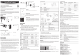
Dimensions / Connections
Duct version
Wall version
Mechanical installation
General recommendations
Relative humidity is extremely temperature-dependent. In order to measure it exactly, the probe and
sensors must be set exactly on the temperature level of the environment that is to be measured.
The installation site can therefore have a signicant inuence on the performance of the device.
Follow the guidelines below to ensure optimum performance:
a) Select a representative installation site: Install the probe at a point where the humidity, tem-
perature and pressure conditions are representative for the environment that is to be measured.
b) Make sure there is sufcient air movement around the probe: An air ow of at least 1 metre/
second accelerates and facilitates adjustment of the probe to changing temperatures.
c) Avoid:
1. Probe too close to heating elements, cooling coils, cold or hot walls, direct sunlight, etc.
2. Probe too close to steam, injectors, humidiers or direct precipitation.
3. Unstable pressure conditions with high air turbulence.
d Insert the probe as far as possible into the environment that is to be measured.
e) Avoid accumulation of condensation at the contact wires of the sensor. Install the probe so
that the tip points down. If that is not possible, install it in horizontal position.
Mounting the duct version
To avoid measurement errors, at least 200 mm of the probe should be inserted into the environ-
ment that is to be measured.
If necessary, use the mounting ange AC1305-M + AC1307 to install the probe and fasten the
transmitter.
AC1305-M + AC1307 Mounting ange
for 15...16 mm probe
Mounting the wall version
Alignment
Mount the transmitter so that the probe points down.
Mounting variant 1
Drill the necessary holes using the drill template drawn on the packaging. Then insert the plugs
delivered with the device and mount the transmitter with the screws.
Electrical installation
Power supply
a) HF53 (3-wire with analogue outputs): 6 to 40 VDC or 6 to 28 VAC.
Max. power consumption: <3.8 Watt
b) HF54 (3-wire galvanic separated with analogue outputs): 9 to 36 VDC or 7 to 24 VAC.
Max. power consumption: <3.8 Watt.
c) HF55 (3-wire with digital output: 17 to 40 VDC or 14 to 28 VAC.
Max. power consumption: <3.8 Watt
Supply voltage / Technology
Type Supply voltage V+ Load Output
3 / 4-wire
HF531S 7...40 VDC / 4... 28 VAC Max. 500 Ω 0...20 mA
HF532S 7...40 VDC / 4...28 VAC Max. 500 Ω 4...20 mA
HF533S 6...40 VDC / 6...28 VAC Min. 1000 Ω 0...1 V
HF534S 10...40 VDC / 8...28 VAC Min. 1000 Ω 0...5 V
HF535S 15...40 VDC / 12...28 VAC Min. 1000 Ω 0...10 V
Galvanically separated
HF541S 9...36 VDC Max. 500 Ω 0...20 mA
HF542S 9...36 VDC Max. 500 Ω 4...20 mA
HF543S 9...36 VDC Min. 1000 Ω 0...1 VDC
HF544S 9...36 VDC Min. 1000 Ω 0...5 VCD
HF545S 9...36 VDC Min. 1000 Ω 0...10 VCD
Digital output
HF556S 17...40 VDC / 14...28 VAC Digital output
HF557S Power over Ethernet (PoE) Digital output
Caution: Wrong supply voltages and excessively high loading of the outputs can
damage the transmitter.
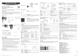
Terminal conguration / Connection diagrams
The type is dened using the table Supply voltage / Technology to then use the following connec-
tion diagrams:
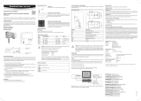
Button MENU:
open / close menu
Button ENTER:
select menu point
Menu navigation:
Buttons + / - change value: increase/decrease
Note: Unauthorised use of the menu can be prevented by locking the setting “Display Menu”
(using the HW4 software > Device Manager > Display).
The main menu points
Main menu Menu points Options / Information Remarks
Decive Settings
Units Metric / English
Contrast LC display contrast
adjustment
Trend On / Off Trend shown on the
display
Device Information
Version Firmware version
Serial No. Serial number
Address Address RS-485
Type Device type
Name Device name User-dened
Sources of error
Measured values can be inuenced by the following factors:
Temperature errors :
Adaptation time too short, cold outside wall, heating elements, sunlight, etc.
Humidity errors:
Steam, water spray, dripping water or condensation at the sensor, etc. Repeatability and long term
stability are, however, not inuenced by these factors even if the probe is exposed to high humidity
or saturation with steam (condensation) over a longer period of time.
Soiling:
By dust in the air. The choice of probe lter depends on the amount of soiling at the measuring
point. The lter must be cleaned or replaced periodically.
Scaling / Adjustment / Firmware update
The following settings can be made with the help of the HW4 software and either the service cable
AC3006 or AC3009:
• new scaling of the outputs
• adjustment
• rmware update
You can nd a detailed description in the manual that you can download from our web site at
www.rotronic.com
Periodic calibration of the probe / transmitter
Both the Pt 100 RTD temperature sensor and the corresponding electronics are very stable and do
not normally need to be changed or calibrated after factory calibration. The long term stability of the
ROTRONIC Hygromer humidity probes is typically better than 1 %rh per year. For maximum accuracy
we recommend calibration of the probe about every six to 12 months. More frequent calibration
can be necessary in applications where the sensor is exposed to pollutants. The calibration can
be performed by the user himself on site or in the laboratory / workshop. For routine calibrations
the probe should be checked at one or two points.
The electronics of the transmitter do not normally require calibration in the eld. They can be
checked easily with the help of the probe simulator in the HW4 software package. The electronics
cannot be repaired in the eld and should be returned to the manufacturer in the case of problems.
For details on calibration, please see the full version of the instruction manual, which you can
download from the internet.
Technical data (measurement)
Humidity: 0...100 %rh
Temperature: –100...200 °C
Accuracy: Probe-dependent: ±0,8 %rh, ±0,1 K @ 23°C (HC2-S)
Protection: IP65
Outputs: Current or voltage signals, digital output depending on order code,
UART service interface
Technical data (
Electronics operating range)
Temperature: –40...60 °C (–10...60 °C with Display)
Humidity: 0...100 %rh, non-condensing
SHORT INSTRUCTION MANUAL
Current output
Voltage output
=
~
K2: V +
K2: V −
K2: GND
K4: OUT1
K4: OUT2
K2: V+
K2: V −
K4: GND
K4: OUT1
K4: OUT2
Equipment depending on model
Digital Analog Power
Supply
USB
Ethernet
PoE
K 1
1
2
3
4
B5
K 4
4
3
2
1
1 2 3
K 2

12.1001.0002
ROTRONIC AG, CH-8303 Bassersdorf
Tel. +41 44 838 11 44, www.rotronic.com
ROTRONIC Messgeräte GmbH, D-76275 Ettlingen
Tel. +49 7243 383 250, www.rotronic.de
ROTRONIC SARL, 56, F - 77183 Croissy Beaubourg
Tél. +33 1 60 95 07 10, www.rotronic.fr
ROTRONIC Italia srl, I- 20157 Milano
Tel. +39 2 39 00 71 90, www.rotronic.it
ROTRONIC Instruments (UK) Ltd, West Sussex RH10 9EE
Phone +44 1293 571000, www.rotronic.co.uk
ROTRONIC Instrument Corp, NY 11788, USA
Phone +1 631 427-3898, www.rotronic-usa.com
ROTRONIC South East Asia Pte Ltd, Singapore 339156
Phone +65 6294 6065, www.rotronic.com.sg
ROTRONIC Shanghai Rep. Office, Shanghai 200233, China
Phone +86 40 08162018, www.rotronic.cn
160
110
210
100
25
235 61
100
160
30
25
30
25
61
160
30
25
30
61
A
Digitaler Messumformer für Feuchte- und Temperatur
Wand- und Kanalversion
Herzlichen Glückwunsch Sie zum Kauf Ihres neuen HygroFlex5-Serie Messumformers. Sie haben
damit ein dem neuesten Stand der Technik entsprechendes Gerät erworben. Bitte lesen Sie diese
Kurz-Anleitung genau durch, bevor Sie das Gerät installieren.
Allgemeine Beschreibung
Die HygroFlex5-Serie Geräte sind universelle Messumformer, mit auswechselbaren HC2-Fühler,
für die Übertragung von Feuchte- und Temperaturmesswerten. Diese Kurzbedienungsanleitung
beschränkt sich auf die Beschreibung der wichtigsten Funktionen und der Installation des Gerätes.
Die detaillierte Bedienungsanleitung nden Sie im Internet unter: www.rotronic.com
Abmessungen / Anschlüsse
Kanalausführung (Typ D)
Wandausführung (Typ W)
Mechanische Installation
Allgemeine Empfehlungen
Die relative Feuchte ist extrem temperaturabhängig. Deren exakte Messung erfordert, dass Fühler
und Sensoren genau auf dem Temperaturniveau der zu messenden Umgebung sind. Daher kann
der gewählte Installationsort einen bedeutenden Einuss auf die Leistung des Gerätes haben.
Die Einhaltung der folgenden Richtlinien garantiert Ihnen eine optimale Leistung des Gerätes:
a) Wählen Sie einen repräsentativen Installationsort: installieren Sie den Fühler an einem Ort, wo
die Feuchte- Temperatur- und Druckverhältnisse für die zu messende Umgebung repräsentativ
sind.
b) Stellen Sie genügend Luftbewegung am Fühler sicher: Eine Luftgeschwindigkeit von mindestens
1 Meter/Sekunde beschleunigt und erleichtert die Anpassung des Fühlers an wechselnde
Temperaturen.
c) Zu vermeiden sind:
(1) Fühler zu nahe an Heizelement, Kühlschlange, kalter oder warmer Wand, direkte Sonnen-
einstrahlung etc.
(2) Fühler zu nahe an Dampf- Injektor, Befeuchter, oder direkter Niederschlag.
(3) Unstabile Druckverhältnissebei grossen Luftturbulenzen.
d) Tauchen Sie den Fühler so weit als möglich in die zu messende Umgebung ein.
e) Vermeiden Sie die Ansammlung von Kondensat an den Kontaktdrähten des Sensors. Instal-
lieren Sie den Fühler so, dass die Fühlerspitze nach untenzeigt. Wenn dies nicht möglich ist,
installieren Sie ihn in horizontaler Position.
Montage der Kanalversion
Zur Vermeidung von Messfehlern sollten mindestens 200 mm des Fühlers in die zu messende
Umgebung eingetaucht sein. Verwenden Sie gegebenenfalls den Montageansch AC1305-M +
AC1307 um den Fühler zu installieren und den Messumformer zu xieren.
AC1305-M + AC1307 Montageansch
für 15...16 mm Fühler
Montage der Wandversion
Ausrichtung
Der Transmitter wird so montiert, dass der Fühler
nach unten gerichtet ist.
Montage Variante 1
Mit der auf der Verpackung aufgezeichneten Bohrschablone werden die nötigen Löcher gebohrt.
Danach werden die mitgelieferten Dübel eingesetzt um dann den Transmitter mit Hilfe der
Schrauben zu montieren.
Elektrische Installation
Stromversorgung
a) HF53 (3-Leiter mit Analogausgängen): 6 bis 40 VDC oder 6 bis 28 VAC.
Maximale Leistungsaufnahme: <3.8 Watt
b) HF54 (3-Leiter galvanisch getrennt mit Analogausgängen): 9 bis 36 VDC.
Maximale Leistungsaufnahme: <3.8 Watt.
c) HF55 (3-Leiter mit Digitalausgängen): 17 bis 40 VDC oder 14 bis 28 VAC.
Maximale Leistungsaufnahme: <3.8 Watt
Versorgungsspannung / Technologie
Typ Spannungsversorgung V+ Bürde Ausgang
3 / 4 Leiter
HF531S 7...40 VDC / 4... 28 VAC Max. 500 Ω 0...20 mA
HF532S 7...40 VDC / 4...28 VAC Max. 500 Ω 4...20 mA
HF533S 6...40 VDC / 6...28 VAC Min. 1000 Ω 0...1 V
HF534S 10...40 VDC / 8...28 VAC Min. 1000 Ω 0...5 V
HF535S 15...40 VDC / 12...28 VAC Min. 1000 Ω 0...10 V
Galvanisch getrennt
HF541S 9...36 VDC Max. 500 Ω 0...20 mA
HF542S 9...36 VDC Max. 500 Ω 4...20 mA
HF543S 9...36 VDC Min. 1000 Ω 0...1 VDC
HF544S 9...36 VDC Min. 1000 Ω 0...5 VCD
HF545S 9...36 VDC Min. 1000 Ω 0...10 VCD
Digitaler Ausgang
HF556S 17...40 VDC / 14...28 VAC Digitaler Ausgang
HF557S Power over Ethernet (PoE) Digitaler Ausgang
Achtung: Falsche Versorgungsspannungen sowie zu grosse Belastungen der Ausgänge
können den Messumformer beschädigen.
Klemmenbelegung / Anschlussschemata
Anhand der Tabelle Versorgungsspannung / Technologie wird der Typ deniert, um folgende
Anschluss-Schemas verwenden zu können:
HF53S, HF54S (Galvanisch getrennt), HF55S
Klemme Beschreibung
K2-1 V – Spannungsversorgung – / Neutral
K2-2 V+ Spannungsversorgung + / Phase
K2-3 Erde
K4-4 GND GND
K4-3 GND GND
K4-2 OUT2 Temperatur-Analogausgang + *
K4-1 OUT1 Feuchte-Analogausgang + **
K1-1 V+ DC (+) 17…24 VDC (+) siehe Bemerkungen unten "K1"
K1-2 GND GND
K1-3 D + RS-485 Bi-directional TX+ / RX +
K1-4 D – RS-485 Bi-directional TX – / RX –
* Für Ausgangsparameter Feuchte & Berechnung:
OUT2 = berechneter Wert, OUT1 = Feuchte
** Für Ausgangsparameter Temperatur & Berechnung:
OUT1 = berechneter Wert, OUT2 = Temperatur
Klemme K2-3: Erde ist standardmässig nicht mit GND verbunden. Wird das gewünscht, muss auf
dem PCB ein Lötauge entfernt werden.
Klemmen K1 (RS-485): Klemmen K1-3 und K1-4 können verwendet werden, um das Gerät zu
speisen (Mehrpunktverbindung). Es können mehrere RS-485 Geräte mit einem starken Netzgerät
15 VDC betrieben werden. In diesem Falle wird die Spannungsversorgung an K2-1 bis K2-2 nicht
verwendet.
Warnung: Stellen Sie sicher, dass bevor Sie den Transmitter ins Netzwerk einbinden und an-
schliessen, alle Einstellungen richtig durchgeführt wurden.
Programmierung
Die Grundeinstellungen der Geräte werden im Werk, gemäss Ihrer Bestellung, vorgenommen.
Die Transmitter werden im Werk justiert, sodass eine Überprüfung oder Nachjustierung bei
der Installation nicht notwendig ist. Die Geräte können sofort nach der Installation in Betrieb
genommen werden.
Display
Bei Modellen mit LC-Display, kann der Wert direkt abgelesen werden.
Taste MENU:
Menü öffnen / schliessen
Taste ENTER:
Auswahl Menüpunkt
Menünavigation
Tasten + / - Wert ändern: Erhöhen / Verringern
Hinweis: Der unbefugte Zugriff auf das Menü kann durch Sperren der Einstellung “Display Menü”
verhindert werden (Verwendung der HW4-Software > Geräte-Manager > Display)
Die wichtigsten Menüpunkte.
Hauptmenü Menü-Punkte Auswahl / Information Hinweise
Decive Settings (Geräteeinstellungen)
Units (Einheiten) Metrisch / Englisch
Contrast (Kontrast) LC-Display
Kontrast-Justierung
Trend (Trendanzeige) Ein / Aus Trendanzeige
auf dem Display
Device Information (Geräte-Informationen)
Version (Version) Firmwareversion
Serial Nbr (Seriennr.) Seriennummer
Address (Adresse) Adresse RS-485
Type (Typ) Gerätetyp
Name (Bezeichnung) Gerätename Benutzerdeniert
Fehlerquellen
Messwerte können durch folgende Einüsse beeinträchtigt werden:
Temperaturfehler:
Durch zu kurze Angleichzeit, kalte Aussenwand, Heizkörper, Sonneneinstrahlung usw.
Feuchtefehler:
Durch Dampf, Wasserspritzer, Tropfwasser oder Kondensation am Sensor usw. Jedoch wird die
Reproduzierbarkeit und Langzeitstabilität dadurch nicht beeinträchtigt, auch wenn der Fühler über
längere Zeit einer hohen Feuchte oder Sättigung mit Wasserdampf (Kondensation) ausgesetzt wurde.
Verschmutzung:
Durch Staub in der Luft. Die Wahl des Fühlerlters ist abhängig vom Verschmutzungsgrad des
Messortes und ist periodisch zu reinigen oder zu ersetzen.
Skalierung / Justierung / Firmware update
Mit Hilfe der HW4 Software und dem Servicekabel AC3006 können folgende Einstellungen
durchgeführt werden:
• Neuskalierung der Ausgänge
• Justierung
• Firmware update
Eine detaillierte Beschreibung nden Sie im Manual welches Sie im Internet unter :
www.rotronic.com herunterladen können.
Periodische Kalibrierung des Fühlers / Transmitters
Sowohl der Pt 100 RTD Temperatursensor als auch die dazugehörende Elektronik sind sehr stabil
und müssen nach der Werkskalibrierung normalerweise nicht verändert oder kalibriert werden.
Die Langzeitstabilität der ROTRONIC Hygromer Feuchtefühler ist typischerweise besser als 1 %rF
pro Jahr. Für eine maximale Genauigkeit empfehlen wir eine Kalibrierung der Fühler ca. alle sechs
bis zwölf Monate. In Anwendungen wo der Sensor Schadstoffen ausgesetzt ist, kann eine häugere
Kalibrierung notwendig sein. Die Kalibrierung kann durch den Benutzer selber vor Ort oder im
Labor bzw. in der Werkstatt vorgenommen werden. Für Routine- Kalibrierungen sollte der Fühler
an einem oder zwei Punkten geprüft werden.
Die Elektronik des Transmitters selber erfordert normalerweise keine Kalibrierung im Feld. Sie
kann mit der Verwendung eine Fühlersimulators der HW4 Software auf einfache Weise überprüft
werden. Die Elektronik lässt sich nicht im Feld reparieren und sollte bei Problemen ans Herstel-
lerwerk retourniert werden. Für die Details der Kalibrierung verweisen wir auf die Vollversion des
Bedienerhandbuches, die vom Internet geladen werden kann.
Technische Daten (Messbereich)
Feuchte: 0...100 %rF
Temperatur: –100...200 °C
Genauigkeit: Fühlerabhängig: ±0,8 %rF, ±0,1 K @ 23°C (HC2-S)
Schutzart: IP65
Ausgänge: Strom- oder Spannungssignal, digitaler Ausgang je nach Bestellcode,
UART Service Schnittstelle
Technische Daten (
Einsatzbereich Elektronik)
Temperatur: –40...60 °C (–10...60 °C mit Display)
Feuchte: 0...100 %rF, nicht kondensierend
Stromausgang
Spannungsausgang
KURZBEDIENUNGSANLEITUNG
=
~
K2: V +
K2: V −
K2: GND
K4: OUT1
K4: OUT2
K2: V+
K2: V −
K4: GND
K4: OUT1
K4: OUT2
Digital Analog Spannungs-
versorgung
Bestückung abhängig von Modell
USB
Ethernet
PoE
K 1
1
2
3
4
B5
K 4
4
3
2
1
1 2 3
K 2

12.1001.0002
ROTRONIC AG, CH-8303 Bassersdorf
Tel. +41 44 838 11 44, www.rotronic.com
ROTRONIC Messgeräte GmbH, D-76275 Ettlingen
Tel. +49 7243 383 250, www.rotronic.de
ROTRONIC SARL, 56, F - 77183 Croissy Beaubourg
Tél. +33 1 60 95 07 10, www.rotronic.fr
ROTRONIC Italia srl, I- 20157 Milano
Tel. +39 2 39 00 71 90, www.rotronic.it
ROTRONIC Instruments (UK) Ltd, West Sussex RH10 9EE
Phone +44 1293 571000, www.rotronic.co.uk
ROTRONIC Instrument Corp, NY 11788, USA
Phone +1 631 427-3898, www.rotronic-usa.com
ROTRONIC South East Asia Pte Ltd, Singapore 339156
Phone +65 6294 6065, www.rotronic.com.sg
ROTRONIC Shanghai Rep. Office, Shanghai 200233, China
Phone +86 40 08162018, www.rotronic.cn
160
110
210
100
25
235 61
100
160
30
25
30
25
61
160
30
25
30
61
A
Versione per canali, versione per pareti
Trasduttori digitali per umidità & temperatura
Ci congratuliamo per il Vostro acquisto di un nuovo trasmettitore della Serie HygroFlex5. Avete
acquistato uno strumento al passo con le tecnologie più moderne. Prima di installare lo strumento,
si prega di leggere la presente guida rapida.
Descrizione generale
Gli apparecchi della Serie HygroFlex5 sono trasmettitori universali, per sonde intercambiabili HC2,
per la trasmissione di valori di umidità e temperatura. La presente guida rapida si limita a descrivere
le funzioni principali dello strumento e la sua installazione. Le istruzioni d’uso dettagliate sono
disponibili in Internet all’indirizzo: www.rotronic.com
Dimensioni / connessioni
Montaggio verticale
Montaggio orizzontale
Installazione meccanica
Consigli generici
L’umidità relativa dipende direttamente dalla temperatura. La sua misurazione esatta richiede che
sonda e sensori abbiano esattamente la stessa temperatura dell’ambiente da misurare. Pertanto la
sede di installazione scelta ha un ruolo decisivo per il rendimento dello strumento. Per ottenere un
rendimento ottimale dello strumento si devono assolutamente rispettare le seguenti prescrizioni:
a) Selezionare una sede di installazione rappresentativa per le misurazioni: installare la sonda
in un punto dove le condizioni di umidità, temperatura e pressione siano rappresentative per
l’ambiente che si intende misurare.
b) Garantire che la sonda sia sottoposta a sufciente ventilazione: Una velocità dell’aria di almeno
1 metro/secondo velocizza e facilita l’adattamento della sonda alle oscillazioni di temperatura.
c) Condizioni da evitare:
1. Sonda troppo vicina a elementi riscaldanti, serpentine di raffreddamento, pareti fredde o
calde, esposizione diretta ai raggi solari ecc.
2. Inserire il più possibile la sonda nell’ambiente che si intende misurare.
3. Rapporti di pressione instabili con eccessive turbolenze dell’aria.
d) Inserire il più possibile la sonda nell’ambiente che si intende misurare.
e) Evitare la formazione di condensa sui li di contatto della sonda. Installare la sonda in modo
che la punta sia rivolta verso il basso. Nel caso non sia possibile, installarla in posizione
orizzontale.
Montaggio della versione per condotta
Per evitare possibili errori di misurazione, si dovrebbero inserire almeno 200 mm della sonda
nell’ambiente da misurare. Utilizzare eventualmente la angia di montaggio AC1305-M + AC1307
per installare la sonda e ssare il trasmettitore.
.
Flangia di montaggio AC1305-M + AC1307
per sonda da 15...16 mm
Montaggio della versione per pareti
Orientamento
Il trasmettitore va montato in modo che la sonda sia rivolta verso
il basso.
Variante 1 di montaggio
Utilizzando la sagoma di foratura facente parte della confezione si effettuano i fori necessari.
In seguito si inseriscono i tasselli facenti parte della fornitura per poi montare il trasmettitore
Installazione elettrica
Alimentazione di corrente
a) HF53 (versione a 3-li con uscite analogiche): da 6 a 40 VDC oppure da 6 a 28 VAC.
Massime prestazioni <3.8 Watt
b) HF54 (versione a 3-li con uscite analogiche e separazione galvanica): 9 a 36 VDC o 7 a 24 VAC.
Massime prestazioni <3.8 Watt
c) HF55 (versione a 3-li con uscita digitale): da 17 a 40 VDC oppure da 14 a 28 VAC.
Massime prestazioni <3.8 Watt
Tensione di alimentazione / tecnologia
Typo Alimentazione di tensione V+ Carico Uscita
Conduttore 3 / 4
HF531S 7...40 VDC / 14...28 VAC Max. 500 Ω 0...20 mA
HF532S 7...40 VDC / 14...28 VAC Max. 500 Ω 4...20 mA
HF533S 6...40 VDC / 6...28 VAC Min. 1000 Ω 0...1 V
HF534S 10...40 VDC / 8...28 VAC Min. 1000 Ω 0...5 V
HF535S 15...40 VDC / 12...28 VAC Min. 1000 Ω 0...10 V
Separazione galvanica
HF541S 9...36 VDC Max. 500 Ω 0...20 mA
HF542S 9...36 VDC Max. 500 Ω 4...20 mA
HF543S 9...36 VDC Min. 1000 Ω 0...1 VDC
HF544S 9...36 VDC Min. 1000 Ω 0...5 VCD
HF545S 9...36 VDC Min. 1000 Ω 0...10 VCD
Uscita digitale
HF556S 17...40 VDC / 14...28 VAC Uscita digitale
HF557S Power over Ethernet (PoE) Uscita digitale
Attenzione: tensioni di alimentazione errate o carichi eccessivi sulle uscite possono
danneggiare il trasduttore.
Occupazione dei morsetti / schemi di collegamento
In base alla tabella “Tensione di alimentazione / tecnologia” si denisce il tipo, per poter quindi
utilizzare i seguenti schemi di collegamento:
HF53S, HF54S (separazione galvanica), HF55S
Morsetto Descrizione
K2-1 V – Alimentazione di tensione / Neutro
K1-2 V+ Alimentazione di tensione + / Fase
K1-3 Terra
K4-4 GND GND
K4-3 GND GND
K4-2 OUT2 Uscita analogica temperatura +
K4-2 OUT2 Uscita analogica umidità + (**valore calcolato)
K1-1 V+ DC (+) 17…24 VDC (+) V. nota a seguire "K1"
K1-2 GND GND
K1-3 D+ RS-485 Bi-bidirezionale TX + / RX +
K1-4 D– RS-485 Bi-directional TX – / RX –
** Per l’umidità e il punto di rugiada: Umidità OUT2; punto di rugiada OUT1
Morsetto K2-3: La terra è non collegata come standard a GND. Se è richiesto tale collegamento,
si deve rimuovere un occhiello di saldatura alla scheda di circuito stampata.
Morsetti K1 (RS-485): per alimentare lo strumento (collegamento a più punti) si possono utiliz-
zare i morsetti Si possono far funzionare diversi strumenti RS-485 utilizzando un alimentatore
potente da 15VDC. In tal caso l’alimentazione di tensione su K2-1 no a K2-2 non viene utilizzata.
Avviso: prima di inserire il trasmettitore in rete e di collegarlo, assicurarsi di aver effettuato
correttamente tutte le impostazioni.
Programmazione
Le impostazioni base dello strumento sono effettuate di fabbrica, in accordo alla Vostra ordinazi-
one. I trasmettitori sono regolati di fabbrica e pertanto in fase di installazione non è necessario
effettuare un controllo o una successiva regolazione. Dopo l’installazione è possibile mettere
immediatamente in funzione gli strumenti.
Display
I modelli con display LCD permettono la lettura immediata del valore.
Nota: è possibile evitare un accesso non autorizzato al menu bloccando l’opzione “Display Menu”
(se si utilizza il software HW4 > Manager strumenti > Display).
Le principali opzioni di menu
Menu principale Voci del menu Selezione/Informaziione Note
Decive Settings (Impostazioni apparecchio)
Units (unità) Metrico / inglese
Contrast (Contrasta)
Regolazione del
contrasto del disply LCD
Trend On / Off Visualizzazione
(Visualizzazione trend) sul display del trend
Device Information (Informazioni apparecchio)
Version (Versione) Versione Firmware
Serial Nbr (N° di serie) Numero di serie
Address (Indirizzo) Indirizzo RS-485
Type (Typo) Tipo di apparecchio
Name (Denominazione) Nome dell’apparecchio Denito dall’utente
Fonti di errore
I valori di misurazione sono inuenzati dalle seguenti condizioni:
Errore di temperatura: dovuto a tempi ridotti di adattamento, parete esterna fredda, termosifone,
esposizione ai raggi solari ecc.
Errore di umidità: dovuto a vapore, spruzzi d’acqua, goccioli o condensa sul sensore ecc. Non
vengono però inuenzate la riproducibilità e la stabilità lungo termine, anche se la sonda è stata
sottoposta a lungo ad un livello eccessivo di umidità o a saturazione con vapore acqueo (condensa).
Sporcizia: dovuta a polvere presente nell’aria. La scelta del ltro della sonda dipende dal livello
di imbrattamento della sede di misurazione e tale ltro va pulito o sostituito ad intervalli regolari.
Scala / Regolazione / Firmware update
Grazie al software HW4 e al cavo di servizio AC3006 si possono effettuare le seguenti impostazioni:
• Nuova scala delle uscite
• Regolazione
• Firmware update
Una descrizione dettagliata è riportata nel manuale disponibile per lo scarico all’indirizzo Internet
www.rotronic.com
Calibrazione periodica della sonda / del trasmettitore
Sia il sensore per la temperatura Pt 100 RTD sia i relativi dispositivi elettronici sono estremamente
stabili e di solito non vanno più modicati o calibrati dopo la calibrazione effettuata di fabbrica.
La stabilità a lungo termine della sonda per l’umidità Hygromer ROTRONIC risulta di solito migliore
ad un valore dell’1 % di umidità relativa/anno. Per ottenere la massima precisione possibile,
consigliamo di effettuare una calibrazione della sonda ogni sei – dodici mesi. Per applicazioni che
prevedono un’esposizione del sensore a sostanze nocive potrebbe essere necessario effettuare più
spesso la calibrazione. La calibrazione può essere effettuata direttamente dall’operatore in sede
di applicazione o in un laboratorio o ofcina. Per calibrazioni di routine si dovrebbe effettuare la
calibrazione della sonda con uno o due punti.
Normalmente i dispositivi elettronici del trasmettitore non richiedono alcuna calibrazione in campo.
Utilizzando la funziona di simulazione del software HW4 si può effettuare facilmente un controllo.
Non è possibile riparare i dispositivi elettronici in campo e in presenza di problemi vanno rinviati al
produttore. Per informazioni dettagliate sulla calibrazione, si prega di fare riferimento alla versione
integrale del manuale di istruzioni, disponibile in Internet per lo scarico.
Dati tecnici (range di misurazione)
Umidità 0...100 % ur (umidità relativa)
Temperatura: –100...200 °C
Precisione: in base al tipo di sonda: ±0,8 % ur, ±0,1 K @ 23°C (HC2-S)
Standard di protezione: IP65 eccetto i modelli con interfaccia USB ed Ethernet
Uscite: segnale di corrente o di tensione, uscita digitale in base al codice
d’ordine, interfaccia di servizio UART
Dati tecnici (range di utilizzo)
Temperatura: –40...60 °C (–10...60 °C con display)
Umidità: 0...100% ur (umidità relativa) non condensante
MANUALE D'ISTRUZIONI BREVE
Uscita di corrente
Uscita di tensione
=
~
K2: V +
K2: V −
K2: GND
K4: OUT1
K4: OUT2
K2: V+
K2: V −
K4: GND
K4: OUT1
K4: OUT2
Digitale Analogica Alimentatione
Equipaggiamento dipendente dal modello
Tasto ENTER: selezione
della voce di menu
Tasto MENU:
si apre / si chiudere il menu
Navigazione nel menu
Tasti + / - per la modica valore
USB
Ethernet
PoE
K 1
1
2
3
4
B5
K 4
4
3
2
1
1 2 3
K 2
/