HC2-2GHC2-2GRLRL
USER MANUAL
VOLUME1
Manufactured by R.V.R. ELETTRONICA Italia

HC2-2GRL - User Manual
Version 1.0
© Copyright 2019
R.V.R. Elettronica
Via del Fonditore 2/2c - 40138 - Bologna (Italy)
Phone: +39 051 6010506
Fax: +39 051 6011104
Email: info@rvr.it
Web: www.rvr.it
All rights reserved.
Printed in Italy. No part of this manual may be reproduced, memorized
or transmitted in any form or by any means, electronic or mechanic,
including photocopying, recording or by any information storage and
retrieval system, without written permission of the copyright owner.
File Name: HC2-2GRL_ITA_1.0.indb
Version: 1.0
Date: 29/11/2019
Version History
Date Version Reason Editor
29/11/2019 1.0 First edition J. H. Berti
Notification of intended purpose and limitations of product use
This product is a FM transmitter intended for FM audio broadcasting. It utili-
ses operating frequencies not harmonised in the intended countries of use.
The user must obtain a license before using the product in intended country
of use. Ensure respective country licensing requirements are complied with.
Limitations of use can apply in respect of operating freuency, transmitter
power and/or channel spacing.
Declaration of Conformity
Hereby, R.V.R. Elettronica, declares that this FM transmitter is in complian-
ce with the essential requirements and other relevant provisions of Directive
2014/53/EU.

HC2-2GRL
i
User Manual
Rev. 1.0 - 29/11/19
Technical Specications
HC2-2GRL
Parameters U.M. Value Notes
Frequency range MHz 87.5 ÷ 108
Rated output power W 2000 Continuously variable by software from 0 to maximum
Unbalaced Power Limit W 950
Ambient working temperature °C -5 to + 50
Ambient Working Humidity %85 (Without condensing)
Connector N-Type
Impedance Ohm 50
Power W 100
Connector 7/16" EIA
Impedance Ohm 50
Number of Way 2
Power W 1000
Connector 7/8" EIA
Impedance Ohm 50
Connector N-Type
Impedance Ohm 50
Number of Way 2
AC Supply Voltage VAC 117 ÷ 230 +10% -15%
AC Apparent Power Consumption VA 61
Active Power Consumption W61
Power Factor 0,998
Connector VDE IEC Standard
DC Supply Voltage VDC --
DC Current ADC -- (*)max 25W (**) max 140W
Front panel width mm 483 (19") 19" EIA rack
Front panel height mm 132 (3HE)
Overall depth mm 573
Chassis depth mm 501
Weight kg about 15
Cooling Forced, with internal fan
Acoustic Noise dBA <75
Interlock Connector BNC For remote power inhibition (short is RF off)
Foldback Connector BNC
RS232 Connector DB9 F
I2C bus Connector DB9 F
Telemetry Interface Connector DB25F
Common Bus Connector DB15M
FUSES
On Mains 1x External F 3,15 - 5 x 20 mm
Input device 4 pushbutton
Display Alphanumerical LCD - 2 x 16
8Command ON
20 Command OFF
11
Alarm Reset
16
FWD power
4REF power
2VPA
15 IPA
25
Status ON
12
Status OFF
9Power Good 1
22 Power Good 2
18 Power Good 3
10
Wait
17
Fault
23 Local
5Interlock
Phisical Dimensions
GENERALS
INPUTS
Power Splitter
Power Coupler
OUTPUTS
Power Coupler
Power Splitter
POWER REQUIREMENTS
AC Power Input
DC Power Input
MECHANICAL DIMENSIONS
Telemetry connector outputs
Analogical level
Open Collector
VARIOUS
AUXILIARY CONNECTIONS
HUMAN INTERFACES
TELEMETRY / TELECONTROL
Telemetry connector inputs Pulse to GND

ii User Manual
Rev. 1.0 - 29/11/19
HC2-2GRL
Table of Contents
1. Preliminary Instructions 1
2. Warranty 1
3. First aid 2
3.1 Treatment of electric shocks 2
3.2 Treatment of electrical burns 2
4. General description 3
4.1 Unpacking 3
4.2 Features 3
4.3 Description of the Front Panel 5
4.4 Description of the Rear Panel 6
4.5 Description of the Connectors 7
5. Installation and Conguration Procedure 9
5.1 Installation 10
5.2 Software 17
6. Identication and Access to the Modules 26
6.1 IdenticationoftheModules 26
6.2 Spare Parts List 27
7. Principles of Operation 28
7.2 Description of the modules 28
7.2 Compensation 30
8. Maintenance and Repair Procedures 32
8.1 Introduction 32
8.2 Safety Considerations 32
8.3 Ordinary maintenance 32
8.4 ReplacingtheModules 34

HC2-2GRL
1 / 36
User Manual
Rev. 1.0 - 29/11/19
1. Preliminary Instructions
• General Notices
The equipment in question is to be considered for
use, installation and maintenance by “trained” or
“qualied” personnel aware of the risks associated with
working on electrical and electronic circuits.
The definition of “trained” means personnel with the
technical knowledge required to use the device in
a manner that ensures their own safety and that of
other unqualified personnel under their direct
supervision when working on the equipment.
The denition of “qualied” means personnel with the training
and experience required to use the device in a manner
that ensures their own safety and that of other unqualied
personnel under their direct supervision when working on
the equipment.
CAUTION: The device may be equipped with an
ON/OFF switch which may not completely remove
voltage inside the device. It is necessary to disconnect
the power cord, or turn o the power panel, before
carrying out technical work, making sure that
the safety earth connection is connected.
Technical work that involves inspection of the device
with live circuits must be carried out by trained and
qualied personnel in the presence of a second trained
person who is ready to intervene by disconnecting the
power supply in case of need.
R.V.R. Elettronica assumes no responsibility for injury or
damage caused by improper or incorrect use by personnel,
whether trained and qualied or not.
CAUTION: The device is not resistant to the ingress
of water and inltration could seriously compromise its
correct performance. To prevent re or electric shock,
do not expose this equipment to rain, inltration or
moisture.
Please observe local regulations and re regulations when
installing and using this equipment.
CAUTION: The device in question has internal parts
that pose the risk of electric shock: always disconnect
the power supply before removing the covers or any
other part of the equipment.
Ventilation slots and holes are provided to ensure reliable
operation of the product and to protect it from overheating.
These slots must not be obstructed or covered. The slots
must not be obstructed under any circumstances.
The product should not be incorporated into a rack unless
it is provided with adequate ventilation or the manufacturer's
instructions have been followed.
CAUTION: This equipment can radiate radio
frequency energy, and if not installed in accordance
with the instructions in the manual and the regulations
in force it can interfere with radio communications.
CAUTION: This equipment has an earth connection
on both the power cord and the chassis. Make sure they
are connected correctly.
Operating this appliance in a residential environment can
cause radio disturbances; in this case, the user may be
required to take appropriate measures.
The specications and information given in this manual are
provided for informational purposes only, and may therefore
be subject to change at any time without notice and should
not be seen as binding to R.V.R. Elettronica.
R.V.R. Elettronica assumes no responsibility or liability for
any errors or inaccuracies that may appear in this manual,
including the products and software described in it; and
reserves the right to make changes to the design and/or
technical specications of the equipment, as well as to this
manual, without prior notice.
• Notice regarding the intended use and limitations on
use of the product.
This product is a radio transmitter suitable
for frequency modulated audio broadcasting
service. It uses operating frequencies that are
not harmonized in the designated user states.
The user of this product must obtain specic authorization
for use of the radio spectrum from the spectrum
management authority of the designated user state,
before putting this equipment into operation.
The operating frequency, the power of the transmitter, as
well as other characteristics of the transmission system, are
subject to limitations and are set out in the authorization
obtained.
2. Warranty
R.V.R. Electronica guarantees the absence of
manufacturing defects and the proper functioning of the
products, within the terms and conditions provided.
Please read the terms carefully, because purchasing
the product or accepting the order confirmation
constitutes acceptance of the terms and conditions.
For the latest updates on the legal terms and conditions, please
visit our website (WWW.RVR.IT) which can also be modied,
removed or updated for any reason without notice.
The warranty will be void in the event of opening the
equipment, physical damage, misuse, modification,
repair by unauthorized persons, carelessness and
use for purposes other than those intended.
In the event of a defect, proceed as described below:
1 Contact the retailer or distributor from whom the
equipment was purchased; describe the issue or
malfunction to verify if there is a simple solution.
Retailers and Distributors are able to provide all information
relating to the most common issues; they can usually repair
the equipment much faster than the manufacturer could.
Installation errors can normally be identied directly by
retailers.
2 if your retailer cannot help you, contact R.V.R. Elettronica
and describe the issue; if the sta deems it necessary,
the authorization to send the equipment will be sent to
you with the appropriate instructions;
3 Once you have received authorization, you can return
the unit. Pack it carefully for shipping, preferably using
the original packaging and duly sealing the package.
IMPORTANT
The lightning bolt symbol inside a triangle on the product draws attention to operations for which
care must be taken to avoid the danger of electric shock.
The exclamation point symbol inside a triangle on the product informs the user of the presence
of instructions in the manual accompanying the equipment, which are important for operation
and maintenance (repairs).

2 / 36 User Manual
Rev. 1.0 - 29/11/19
HC2-2GRL
The customer always assumes the risks of loss
(i.e., R.V.R. is never liable for damage or loss), until the
package reaches the R.V.R. facility. For this reason, we
suggest that you insure the goods for their full value.
The goods must be shipped, using C.I.F. values (PAID IN
ADVANCE), to the address specied by the R.V.R.
service manager on the authorization.
The equipment must not be returned without the
authorization for sending as it may be returned to
the sender.
4 Make sure to include a descriptive technical report
mentioning any issues encountered and a copy of
your original invoice indicating the date from which the
warranty is valid.
Spare parts and parts under warranty can be ordered at
the following address. Make sure to include the model and
serial number of the equipment, as well as the description
and number of spare parts.
R.V.R. Elettronica
Via del Fonditore, 2/2c
40138 BOLOGNA ITALY
Tel. +39 051 6010506
3. First aid
Personnel entrusted with installation, use, and maintenance
of the equipment must be familiar with rst aid theory and
practices.
3.1 Treatment of electric shocks
3.1.1 If the victim has lost consciousness
Follow the rst aid principles below.
• Place the victim lying on their back on a hard
surface.
• Open the airway by lifting the neck and pushing
the forehead back (Figure 1).
Figure 1
• If necessary, open their mouth and check their
breathing.
• If the victim is not breathing, start articial
respiration immediately (Figure 2): tilt the
head, close the nostrils, make your mouth
adhere to that of the victim and perform 4 quick
breaths.
Figure 2
• Check the heart rate (Figure 3); in the
absence of a heartbeat, immediately begin
heart massage (Figure 4) by compressing
the sternum approximately in the centre of the
chest (Figure 5).
Figure 3 Figure 4 Figure 5
• In the case of only one rescuer, this person
must maintain a rhythm of 15 compressions
alternating with 2 quick breaths.
• In the case of two rescuers, the rhythm must
be one breath every 5 compressions.
• Do not interrupt heart massage during articial
respiration.
• Call a doctor as soon as possible.
3.1.2 If the victim is conscious
• Cover the victim with a blanket.
• Try to keep the victim calm.
• Loosen the clothes and place the victim in a
lying position.
• Call a doctor as soon as possible.
3.2 Treatment of electrical burns
3.2.1 Extensive burns and cuts to the skin
• Cover the aected area with a clean sheet or
cloth.
• Don't break blisters; remove fabric and items of
clothing adhering to the skin; apply a suitable
ointment.
• Treat the victim as required for the type of
injury.
• Transport the victim to the hospital as quickly
as possible.
• If the arms and legs have been aected, keep
them elevated.
If medical help is unavailable for an hour and the victim is
conscious and not retching, administer a liquid solution of
salt and baking soda: 1 teaspoon of salt and half a teaspoon
of baking soda for every 250ml of water.
Slowly drink about half a glass of solution four times over a
period of 15 minutes.
Discontinue if retching occurs.
Do not give alcohol.
3.2.2 Less serious burns
• Apply cold (not icy) gauze compresses using
as clean a cloth as possible.
• Don't break blisters; remove fabric and items of
clothing adhering to the skin; apply a suitable
ointment.
• If necessary, put on clean and dry clothes.
• Treat the victim as required for the type of
injury.
• Transport the victim to the hospital as quickly
as possible.
• If the arms and legs have been aected, keep
them elevated.

HC2-2GRL
3 / 36
User Manual
Rev. 1.0 - 29/11/19
4. General description
The HC2-2GRL, manufactured by R.V.R. Elettronica, is a hybrid coupler made
with “Strip-Lines” technology. Its function is to divide the RF signal coming from an
exciter by appropriately regulating its relative phases, to supply them to two external
power ampliers and to combine the amplied outputs through a single antenna
output. The HC2-2GRL combines transmitters of 1000 W max power (2 kW total).
The HC2-2GRL is designed to be contained in a 3HE 19” rack box.
4.1 Unpacking
The package contains the following:
1 HC2-2GRL
1 Compliance Documentation
1 Power connector
You can also obtain the following accessories for the equipment from your R.V.R.
retailer:
• Options for the equipment: /AUDIGIN-TFT, /RDS-TEX-2HE, /RDS-TEX-E-
2HE and /TLW-TEX-E-2HE
/LINEOUT-HCGRL
/EXT24V-HCGRL
/LINEOUT-HCGRL
●
/EXT24V-HCGRL
●
●: compatible option / ○: option already included / x : not compatible option
Table 4.1: table of compatibility of the various options
• Spare parts
• Cables
4.2 Features
The nominal operation of a transmitter based on a scheme with a hybrid combiner
such as the HC2-2GRL requires the ampliers to deliver the same power.
Any power dierences (or phase shifts) between the ampliers produce so-called
“imbalance power”, which is partly dissipated inside the combiner. The HC2-2GRL
guarantees operation of the transmitter even if one of the ampliers is completely
out of service. In which case, the power coming from the surviving amplier is
transmitted to the antenna, except for a fraction of it (about 1/4) which is dissipated
inside the combiner.

4 / 36 User Manual
Rev. 1.0 - 29/11/19
HC2-2GRL
The HC2-2GRL is controlled by a microprocessor system which includes an LCD
display and a push-button panel for user interaction, and which performs the
following functions:
• Measurement and display of the working parameters of the coupler
• Activation and deactivation of power delivery
• Protection of the coupler against potentially harmful situations such as power
output, imbalance power, driving power or excessive temperature
• Detection of user-settable warning thresholds (e.g. power emitted below a
certain threshold), which are made available as digital variables on the telemetry
connector
• Communications with external devices
The management software of the HC2-2GRL is based on a menu system.
The user can navigate between the dierent submenus using four buttons: ESC,
, , and ENTER. A fth button is used to reset the alarm counter, if any alarms
have occurred.
The status of the equipment is indicated by ve LEDs on the front panel: ON/OFF,
WAIT, FAULT, LOCAL and FOLDBACK.
At a switch located on the front panel, the coupler can be set to operate in LOCAL
or REMOTE mode:
• the LOCAL mode allows commands to be entered using the buttons on the
front panel and excludes remote control (i.e. via the telemetry connector);
• in REMOTE mode, the remote control is enabled, while with the buttons it is
only possible to view the various parameters, but not to modify them.
LOCAL mode is indicated by lighting of the corresponding yellow LED on the
front panel.
A telemetry connector on the back of the HC2-2GRL provides the measurements
of the device in the form of analogue signals proportional to the values of the
variables. On the same connector there are digital alarm and warning signals and
digital inputs, for example on/o and alarm reset.
The hybrid coupler has an input for external 24Vdc power supply (optional).
This auxiliary power source is used automatically to keep the CPU section functional
in the event of a power failure. In this way it is possible to interact with the device
(locally or remotely) even in the event of a power failure.
The HC2-2GRL can be connected in cascade to the exciter by means of an
interlock cable, to permit deactivation of the power delivery of the exciter in case
of malfunctions in the transmission system. A similar eect can be obtained even
if the exciter does not have the interlock function, by connecting its power supply
to the auxiliary power socket of the HC2-2GRL “AUX OUT AC LINE” (optional).

HC2-2GRL
5 / 36
User Manual
Rev. 1.0 - 29/11/19
4.3 Description of the Front Panel
Figure 4.1
[1] DISPLAY Liquid crystal display.
[2] ON Green LED, illuminated when the hybrid coupler is powered.
[3] WAIT Yellow LED indicating that the hybrid coupler is waiting for a
condition preventing power delivery to be eliminated.
[4] FAULT Red LED indicating the presence of a malfunction that can no
longer be solved automatically.
[5] LOCAL Yellow LED, illuminated when the exciter is set to Local mode.
[6] FOLDBACK Yellow LED, illuminated when the foldback function has been
triggered (automatic reduction of power delivery if connected to the
exciter that implements the function, as for example in PTX-LCD).
[7] BRIGHTNESS Display contrast adjustment trimmer.
[8] ALARM RESET Button for manual reset of the protection system.
[9] LOC/REM Remote or local control mode selector.
[10] ESC Button to be pressed to exit a menu.
[11] Button for navigating the menu system and for changing
parameters.
[12] Button for navigating the menu system and for changing
parameters.
[13] ENTER Button for conrming a parameter and for entering the menus.
[14] AIR FLOW Air intake for the combiner and divider circuit.
[15] POWER ADJ. Power adjustment trimmer
[16] PHASE ADJ. Phase adjustment of RF channels (Depends on hardware version).

6 / 36 User Manual
Rev. 1.0 - 29/11/19
HC2-2GRL
4.4 Description of the Rear Panel
Figure 4.2
[1] INPUT Exciter input connector (N type connector).
[2] OUTPUT 1 Output 1 of the divider circuit (type N connector) to drive amplier A.
[3] OUTPUT 2 Output 2 of the divider circuit (type N connector) to drive amplier B.
[4] COM BUS DB15 connector for interfacing with other devices
[5] RS232 DB9 connector for connecting the device to external devices.
[6] INPUT 1 Input 1 of the combiner circuit (7/16” EIA Flange) coming from
amplier A.
[7] OUTPUT Output of the combiner circuit (7/8” EIA Flange).
[8] R.F. TEST BNC RF monitor output. The output level is -60 dB below the output
power in the 87.5-108 MHz band (to be used for monitoring the FM
band only).
[9] INPUT 2 Input 2 of the combiner circuit (7/16” EIA Flange) coming from
amplier B.
[10] 24 Vdc IN + Connector for external 24 Vdc power supply for the emergency
power supply of the CPU ± 250mA (optional). Positive (red).
[11] MAINS VOLTAGE VDE socket for mains supply.
[12] MAIN FUSE Protection fuse for the main AC output. Power Line.
[13] 24 Vdc IN - Connector for external 24 Vdc power supply for the emergency
power supply of the CPU ± 250mA (optional). Negative (black).
[14] LINE OUT FUSE Protection fuse for the auxiliary AC output. Power Line (optional).
[15] LINE OUT Auxiliary VDE power socket for powering external devices, typically
an exciter (optional).
[16] INTERLOCK BNC connector to disable an external device, such as an exciter.
In case of faults, the central conductor is grounded.
[17] FOLDBACK BNC connector for “foldback”.
[18] TELEMETRY DB25 telemetry connector.
[19] I2C DB9 connector for I2C standard connections.
[20] HEAT SINK Heat sink.

HC2-2GRL
7 / 36
User Manual
Rev. 1.0 - 29/11/19
4.5 Description of the Connectors
4.5.1 Remote
Type: DB25 female
Pin Name Type Meaning
1 Imbalance Power Ana Out 3.9V x 950 W
2 Ch_4 Disabled
3 GND GND
4 Reected Power Ana Out 4.3V x 200 W
5 OC_ECC Dig Out OC Active in case of interlock
6 OC_SET4 Disabled
7 GND GND
8 IN_ON Dig In “ON” command
9 OC_SET1 Dig Out OC Active when SET1 threshold is exceeded
10 OC_WAIT Dig Out OC Active in case of “Wait” alarm
11 IN_RST Dig In “Reset alarms” command
12 OC_OFF Dig Out OC Active when OFF
13 IN_INH Dig In Maintain at GND to inhibit
14 TEMP Ana Out 3.9V x 70°
15 Ch_5 Disabled
16 Forward Power Ana Out 4.3V x 2000 W
17 OC_FAULT Dig Out OC Active in case of “Fault” alarm
18 OC_SET3 Dig Out OC Active when SET3 threshold is exceeded
19 Ch_3 Disabled
20 IN_OFF Dig In “OFF” command
21 GND GND
22 OC_SET2 Dig Out OC Active when SET2 threshold is exceeded
23 LOC Dig Out.
24 VNS +12 Vdc Not stabilized
25 OC_ON Dig Out OC Active when ON.
Note:
• To send a command to the HC2-2GRL (ON, OFF, Reset), ground the relative
pin for about 500 ms
• OC (Open Collector) outputs are considered “Active” when conducting
4.5.2 RS232
Type: DB9 female
1 NC
2 TXD
3 RXD
4 Internally connected with 7 and 8
5 GND
6 NC
7 Internally connected with 4 and 8
8 Internally connected with 4 and 7
9 NC

8 / 36 User Manual
Rev. 1.0 - 29/11/19
HC2-2GRL
4.5.3 I2C Connector
Type: DB9 female - Used for I2C connections
1 NC
2 SDA Serial DAta
3 SCL Serial CLock
4 NC
5 GND GND
6 NC
7 NC
8 NC
9 NC

HC2-2GRL
9 / 36
User Manual
Rev. 1.0 - 29/11/19
5. Installation and Conguration Procedure
Instructions are given in this chapter on installation and conguration of the
equipment. Carefully perform all the steps described in this chapter both upon
initial start-up and every time the main conguration is changed, for example when
moving to a new transmission station or when replacing the equipment.
IMPORTANT: always disconnect the mains power before carrying out any type
of installation and/or maintenance. It is imperative to cut o the power supply to
avoid electric shock hazards that could cause damage to property and physical
harm, serious injuries or even death.
The equipment must only be installed by qualied personnel.
Qualied personnel are personnel who comply with all the safety directives, laws
and standards that apply to the installation and operation of this device.
The choice of qualied and duly trained personnel is always the responsibility of
the employer, since the employer is always the one in the best position to judge
whether a worker is suitable for a particular job and therefore capable of ensuring
their safety while respecting the applicable law on occupational safety.
Employers must provide their personnel with adequate training in electrical devices,
and ensure that they are familiar with the content of this manual.
Compliance with the safety instructions set out in this manual or with the legislation
indicated does not relieve the personnel from the duty to also comply with other
specic standards relating to the installation, place, country or other circumstances
concerning the equipment.
IMPORTANT: there is a danger of possible electric shocks and it is therefore
mandatory to comply with the applicable safety law regarding electrical aspects.
Once congured, the equipment is ready for normal operation and no further
intervention is required since all the parameters are saved automatically for when
the equipment is switched o and on again either intentionally or unintentionally.
The performance and functions of the hardware and rmware of the equipment
are described in more detail in the following chapters: please refer to the relevant
sections of the manual for further information on what is covered in this chapter.
IMPORTANT: during all phases of conguration and testing of the transmitter of
which this equipment forms part, always keep to hand the test table (“Final Test
Table”) accompanying the equipment: this document covers all the operating
parameters of the equipment set and checked at the time of testing after production.

10 / 36 User Manual
Rev. 1.0 - 29/11/19
HC2-2GRL
5.1 Installation
5.1.1 General Requirements
The ventilation of the equipment and workplace must be suitable for maintenance
according to the directive in force in the country in which this equipment is installed.
To ensure correct operation of the appliance, there must be a clearance of at least
50 cm at the front and back of the device to facilitate the circulation of air through
the ventilation grids.
In any case, the clearances must be in accordance with the safety directive in
force in the country where this equipment is installed.
This device has been designed to operate at temperatures between -10 °C and
45 °C without loss of performance. The ambient air must be dust-free and not
condensed; the maximum humidity must never exceed 95%.
In particular environmental conditions it should be remembered that temperature
uctuations can cause condensation. If the place where this device is located should
be subject to these physical events, it is advisable to monitor the device once it is
put into service, in addition to trying to protect the device itself as best as possible.
IMPORTANT: never power up the equipment in the presence of condensation.
This problem can occur more frequently in the case of equipment stored for a long
time or used as active backup.
The RF antenna, power supply and connection cables must have a section suitable
for the maximum current intensity.
5.1.2 Preliminary checks
Unpack the appliance by removing the wrapping and, before any other operation,
check for any damage due to transport. Carefully check that all connectors are
in perfect condition and verify the absence of moisture. Otherwise, wait until it is
completely dry.
If any issues occur during this first phase, contact the after-sales service
immediately.
The main fuse is accessible from the outside on the rear panel. Remove the fuse
block with a screwdriver to check its condition and replace it if necessary. The fuses
to be used are:

HC2-2GRL
11 / 36
User Manual
Rev. 1.0 - 29/11/19
HC2-2GRL
@ 230 Vac
Main fuse (1x) F 3.15A type 5x20
Table 5.1: Fuses
5.1.3 Placement of the device
Useful tips for correct installation:
• Avoid the presence of external elements near the ventilation inlets and outlets,
as they could prevent proper ventilation of the device.
• Avoid proximity to a source of heat or ammable gas.
• Limit places subject to accumulation of humidity, dust, sand or salt or
environments that could compromise correct operation of the equipment.
• Avoid installing the equipment in inhabited places due to possible noise pollution,
or on lightweight supports. The device may hum during operation due to forced
ventilation. The mounting surface must be able to withstand the weight of the
device and must be solid.
Note: below we will refer to a complete station of which the device can form a part.
The same procedures also apply if the device is used as a standalone one.
The device is generally connected inside a 19” rack and xed with M5 screws in
the designated holes.
The device must be installed at least 1 metre from the ground.
Install the rack where the transmitter will be operated. The rack is mounted on
wheels for ease of movement: once it is put into position it is advisable, therefore,
to use the four screws at the base of the rack to stabilize it perpendicular to the
ground.
The environment where the rack is installed should be air conditioned at about
25 °C and equipped with a lter for the elimination of dust and salt.

12 / 36 User Manual
Rev. 1.0 - 29/11/19
HC2-2GRL
The station normally has an air outlet at the rear of the equipment: in which case,
ensure adequate ventilation of the room.
COLD
HOT
50cm
Alternatively it is cooled by forced ventilation and the air intake is located on the
roof of the equipment. A hose approximately 1.5 metres in length is recommended.
COLD
HOT
50cm

HC2-2GRL
13 / 36
User Manual
Rev. 1.0 - 29/11/19
It is strongly recommended to install the rack at least 50 cm from the rear and side
walls in order to allow optimal air ow and ease of maintenance.
50cm
50cm
COLD
HOT
5.1.4 Power supply connections of the device
Prepare the following connection (valid for both functional tests and final
commissioning):
√ Single-phase mains power connector, 230 (-15% / + 10%) Vac.
A conductor section of at least 1.5 mm2 is recommended.
Note: to ensure the safety of the operators, prepare the wiring according to the
laws and regulations in the country where this equipment is installed.
Connect the mains cable to the MAINS socket on the rear panel.
Connecting the MAINS socket
Caution: To avoid the risk of damaging the equipment, it is essential that this
is properly earthed. It is mandatory, therefore, to check the eciency of the earth
connection of your system.

14 / 36 User Manual
Rev. 1.0 - 29/11/19
HC2-2GRL
Note: to ensure both the safety of the operators and correct operation of the
equipment, it is essential that the mains system is earthed and properly connected
to the equipment.
Useful tips for a correct connection:
• Prepare suitable earthing of the electrical system. This oers both direct
protection, as it prevents shocks when direct contact is made with the
metal casings of the equipment, and indirect protection, as it cuts off
the supply of energy when dispersion occurs due to poor insulation.
This can be done independently also with an earthing rod and inspection pit
installed by the qualied personnel of a specialised company.
• Provide internal lightning protection such as a surge arrester (internal SPD) or
a circuit breaker, to be installed by qualied personnel in the distribution panel.
This solution allows to protect from violent atmospheric electric discharges that
hit the surrounding ground up to several kilometres.
• Provide internal protection against disturbances on the distribution line such as
EMI lters or line voltage stabilizers, to be installed by qualied personnel in the
distribution panel, which can lter disturbances caused by electrical equipment
and sudden surges on the line, as well as permit voltage control.
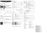
5.1.5 Signal and RF connections
Prepare the following connection (valid for both functional tests and final
commissioning):
√ For functional tests only:
• a dummy load with 50 Ohm impedance and of appropriate power (minimum
2000W for HC2-2GRL).
• Coaxial cable with BNC connectors for connecting the INTERLOCK signal to
the load protection.
MODEM
RS232
SERVICE/RDS
SCA2
MPX
LEFTRIGHT
10KΩ
MAINS VOLTAGE
600Ω
600Ω
RIGHT
ADJ
10KΩ
ADJ
ADJ
ADJADJ
STEREO MONO
10KΩ 50Ω
MPX IMP
MODE
LEFT/MONO INTERLOCK IN REMOTE
EXT AGC
RFL FWD
SCA1/RDS
PREEMPHASIS
RIGHT
4
4
ON
2
75μS
3
ON
2
3
LEFT
PREEMPHASIS SETTING
1
50μS
1
AES/EBU TOSLINK ADJ
R L
EXT REF
10MHz
CARRIER
FREQ. ADJ
PILOT
LVL
MAINS
FUSE
R.F. TEST
max 20dBm
PHASE
ADJ
19KHz PILOT
OUT
+
24Vdc
R.F. OUTPUT
50 Ω
TEX30LCD/S
HC2-2GRL
PJ1002C-LCD #1
PJ1002C-LCD #2
INTERLOCK
INPUT 2
POWER COUPLER
INPUT 1
LINE OUT
Options
Date
Serial n°
Model Type
MAINS VOLTAGE
COM BUS
INPUT
+-
INTERLOCK
IN2
IN1
OUT2
POWER SPLITTER
OUT1
AMPLIFIERS
B
A
OUTPUT
POWER COUPLER
I²C BUS
FOLDBACK
TELEMETRY
RS232
OUTPUT 2
POWER SPLITTER
INPUT OUTPUT 1
OUTPUT
R.F. TEST
-60dBc
MAINS FUSE
(MAX 6,3A)
LINE OUT FUSE
(MAX 6,3A)
CPU BACKUP
SUPPLY
24V
DC
TOSLINK
ADJ
L R
AES/EBU
SERVICE
MODEM
RS232
I²C BUS
GSM ANT
MAINS SWITCH
MAINS FUSEMAINS FUSE
MAINS VOLTAGE
----------------------
Date
REMOTE
Options
Serial n° --------------------------
-------------------------------
Model Type
---------------------------
COMMMON BUS
AGC
FWD
R.F.
OUTPUT
50Ω
R.F.
TEST
-60dBc
INTERLOCK
OUT
INTERLOCK
IN
INPUT
PWR
TOSLINK
ADJ
L R
AES/EBU
SERVICE
MODEM
RS232
I²C BUS
GSM ANT
MAINS SWITCH
MAINS FUSEMAINS FUSE
MAINS VOLTAGE
----------------------
Date
REMOTE
Options
Serial n° --------------------------
-------------------------------
Model Type
--------------------- ------
COMMMON BUS
AGC
FWD
R.F.
OUTPUT
50Ω
R.F.
TEST
-60dBc
INTERLOCK
OUT
INTERLOCK
IN
INPUT
PWR
INTERLOCK signal connection

HC2-2GRL
15 / 36
User Manual
Rev. 1.0 - 29/11/19
• Coaxial cable with BNC connectors for connecting the COMMON BUS signal.
MODEM
RS232
SERVICE/RDS
SCA2
MPX
LEFTRIGHT
10KΩ
MAINS VOLTAGE
600Ω
600Ω
RIGHT
ADJ
10KΩ
ADJ
ADJ
ADJADJ
STEREO MONO
10KΩ 50Ω
MPX IMP
MODE
LEFT/MONO INTERLOCK IN REMOTE
EXT AGC
RFL FWD
SCA1/RDS
PREEMPHASIS
RIGHT
4
4
ON
2
75μS
3
ON
2
3
LEFT
PREEMPHASIS SETTING
1
50μS
1
AES/EBU TOSLINK ADJ
R L
EXT REF
10MHz
CARRIER
FREQ. ADJ
PILOT
LVL
MAINS
FUSE
R.F. TEST
max 20dBm
PHASE
ADJ
19KHz PILOT
OUT
+
24Vdc
R.F. OUTPUT
50 Ω
TEX30LCD/S
HC2-5GRL
PJ1002C-LCD #1
PJ1002C-LCD #2
COMMON BUS
INPUT 2
POWER COUPLER
INPUT 1
LINE OUT
Options
Date
Serial n°
Model Type
MAINS VOLTAGE
COM BUS
INPUT
+-
INTERLOCK
IN2
IN1
OUT2
POWER SPLITTER
OUT1
AMPLIFIERS
B
A
OUTPUT
POWER COUPLER
I²C BUS
FOLDBACK
TELEMETRY
RS232
OUTPUT 2
POWER SPLITTER
INPUT OUTPUT 1
OUTPUT
R.F. TEST
-60dBc
MAINS FUSE
(MAX 6,3A)
LINE OUT FUSE
(MAX 6,3A)
CPU BACKUP
SUPPLY
24V
DC
TOSLINK
ADJ
L R
AES/EBU
SERVICE
MODEM
RS232
I²C BUS
GSM ANT
MAINS SWITCH
MAINS FUSEMAINS FUSE
MAINS VOLTAGE
----------------------
Date
REMOTE
Options
Serial n° --------------------------
-------------------------------
Model Type
---------------------------
COMMMON BUS
AGC
FWD
R.F.
OUTPUT
50Ω
R.F.
TEST
-60dBc
INTERLOCK
OUT
INTERLOCK
IN
INPUT
PWR
TOSLINK
ADJ
L R
AES/EBU
SERVICE
MODEM
RS232
I²C BUS
GSM ANT
MAINS SWITCH
MAINS FUSEMAINS FUSE
MAINS VOLTAGE
----------------------
Date
REMOTE
Options
Serial n° --------------------------
-------------------------------
Model Type
--------------------- ------
COMMMON BUS
AGC
FWD
R.F.
OUTPUT
50Ω
R.F.
TEST
-60dBc
INTERLOCK
OUT
INTERLOCK
IN
INPUT
PWR
COMMON BUS connection
√ Connection cable kit including:
• RF cable for the output towards the load / antenna (50 Ohm coaxial cable with
standard 7/8” type connector).
• RF cables for amplier input (2x 50 Ohm coaxial cables with standard 7/16”
type connector).
• RF cable for exciter input (50 Ohm coaxial cable with N type connector).
• RF cables for output to ampliers (2x 50 Ohm coaxial cable with N type
connector).
MODEM
RS232
SERVICE/RDS
SCA2
MPX
LEFTRIGHT
10KΩ
MAINS VOLTAGE
600Ω
600Ω
RIGHT
ADJ
10KΩ
ADJ
ADJ
ADJADJ
STEREO MONO
10KΩ 50Ω
MPX IMP
MODE
LEFT/MONO INTERLOCK IN REMOTE
EXT AGC
RFL FWD
SCA1/RDS
PREEMPHASIS
RIGHT
4
4
ON
2
75μS
3
ON
2
3
LEFT
PREEMPHASIS SETTING
1
50μS
1
AES/EBU TOSLINK ADJ
R L
EXT REF
10MHz
CARRIER
FREQ. ADJ
PILOT
LVL
MAINS
FUSE
R.F. TEST
max 20dBm
PHASE
ADJ
19KHz PILOT
OUT
+
24Vdc
R.F. OUTPUT
50 Ω
TEX30LCD/S
HC2-2GRL
PJ1002C-LCD #1
PJ1002C-LCD #2
RF
INPUT 2
POWER COUPLER
INPUT 1
LINE OUT
Options
Date
Serial n°
Model Type
MAINS VOLTAGE
COM BUS
INPUT
+-
INTERLOCK
IN2
IN1
OUT2
POWER SPLITTER
OUT1
AMPLIFIERS
B
A
OUTPUT
POWER COUPLER
I²C BUS
FOLDBACK
TELEMETRY
RS232
OUTPUT 2
POWER SPLITTER
INPUT OUTPUT 1
OUTPUT
R.F. TEST
-60dBc
MAINS FUSE
(MAX 6,3A)
LINE OUT FUSE
(MAX 6,3A)
CPU BACKUP
SUPPLY
24V
DC
TOSLINK
ADJ
L R
AES/EBU
SERVICE
MODEM
RS232
I²C BUS
GSM ANT
MAINS SWITCH
MAINS FUSEMAINS FUSE
MAINS VOLTAGE
----------------------
Date
REMOTE
Options
Serial n° --------------------------
-------------------------------
Model Type
---------------------------
COMMMON BUS
AGC
FWD
R.F.
OUTPUT
50Ω
R.F.
TEST
-60dBc
INTERLOCK
OUT
INTERLOCK
IN
INPUT
PWR
TOSLINK
ADJ
L R
AES/EBU
SERVICE
MODEM
RS232
I²C BUS
GSM ANT
MAINS SWITCH
MAINS FUSEMAINS FUSE
MAINS VOLTAGE
----------------------
Date
REMOTE
Options
Serial n° --------------------------
-------------------------------
Model Type
--------------------- ------
COMMMON BUS
AGC
FWD
R.F.
OUTPUT
50Ω
R.F.
TEST
-60dBc
INTERLOCK
OUT
INTERLOCK
IN
INPUT
PWR
RF signal connection
CAUTION: risk of burns due to RF. Before connecting the antenna cable,
make sure that the equipment cannot emit RF at the output.
CAUTION: For reasons of electromagnetic compatibility, only double shielded
cables should be used at the RF output.

16 / 36 User Manual
Rev. 1.0 - 29/11/19
HC2-2GRL
Connect the exciter RF output cable to the N-type input connector of the combiner’s
splitter section. Connect two cables between the N-type output connectors of
the splitter section and the RF inputs of the two ampliers. Connect two cables
between the output connectors of the two ampliers and the 7/16” EIA type inputs
of the combiner’s coupling section.
Connect the 7/8” EIA type output connector of the combiner section to the antenna
or to a dummy load capable of dissipating the power involved. Connect with
a coaxial cable one of the BNC INTERLOCK connectors to the INTERLOCK
connector of the exciter (see the diagram included with each station for reference).
Connect the FOLDBACK connector to the EXT. A.G.C. input of the exciter, if
envisaged in the conguration (see station manual).
The hybrid combiner must be installed in a rack that includes an anti-tear device
to prevent the possibility of accidentally disconnecting the power leads.
CAUTION: To avoid electric shocks and electrocution, never touch the RF
output connector when the equipment is powered up and with no load
connected.
Note: to ensure both the safety of the operators and correct operation of the
equipment, it is essential that the mains system is earthed and properly connected
to the equipment.
5.1.6 Initial start-up and setting of operation
For initial start-up, follow the procedure below.
Due to its function, an HC2-2GRL is always used inside a transmitter which includes
an exciter and two RF ampliers. The description given in this section therefore
refers to these devices in general.
When the HC2-2GRL is powered up, check that the ON lamp lights up. The LCD
display immediately shows a presentation screen, after which it switches to the
default screen that shows the forward and reected power values.
Activate the exciter at minimum power and wait for it to lock onto the working
frequency. Once the exciter has locked on, gradually increase its output power,
checking the exciter instruments, the amplifiers and the combiner display.
Increase the power of the exciter until the combiner output reaches the desired
value, that is, the full power of the station at the very most.
Page is loading ...
Page is loading ...
Page is loading ...
Page is loading ...
Page is loading ...
Page is loading ...
Page is loading ...
Page is loading ...
Page is loading ...
Page is loading ...
Page is loading ...
Page is loading ...
Page is loading ...
Page is loading ...
Page is loading ...
Page is loading ...
Page is loading ...
Page is loading ...
Page is loading ...
Page is loading ...
Page is loading ...
Page is loading ...
Page is loading ...
Page is loading ...
/