
TB35
The concept of airless fluid delivery is a very simple one; the idea
is to move the material from the bucket to the substrate in as little
time as possible. Using the proper equipment with the proper set
up is essential in the success of the operation. The steps are easy
to understand and follow.
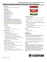
The concept of airless is spraying materials without conventional
air-powered systems. This eliminates the need for air compres-
sors, fluid tanks, and bulky hoses. The diagram below shows the
basic components of a Titan Tool Epic Series fluid section. Most
airless spray units are similar in design and will accomplish the
same thing. On all units, there is an inlet valve, and an outlet
valve within the piston. The piston is held in a sleeve or with
packings that will not allow fluid to leave the chamber under
pressure. As the piston goes down, the upper and lower valves
open, allowing fluid into the inside of the piston. When the
piston goes up, the valves close and the material is pressurized
and forced into the manifold. There is a pressure switch in the
manifold that will tell the controls to either stop the piston
movement or continue, depending on the desired pressure.
In the manifold, there is usually an interchangeable filter and the
connections for the hoses.
As you see, the piston is in the center of the fluid section, and the
notch at the top is where the output of the motor or gears
connects to the section. In this case, the packings are stationary.
The material is pressurized in the piston as it travels up and
down. This motion forces the material through the small opening
at the top of the piston and into the manifold, creating pressure
within the manifold. From the manifold, the material is filtered and
directed to the hose outlet and into the spray gun.
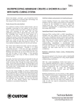
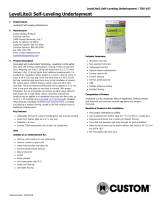
LX 80 Spray Gun Gun filters
L 70 In Line Spray Gun
Gun extensions
CUSTOM
®
recommends the two spray guns shown here. The LX
80 (shown with both four-finger and two-finger trigger set ups) is
for use when applying material to walls. Combining the L 70 In
Line with a three-foot extension and swivel head is the best
assembly for floor work. Both of these spray guns allow
for filtering in the gun handle. For RedGard
®
, a coarse (green
tip) filter should be installed. Filters will have to be cleaned
occasionally to ensure proper flow of material to the tip.
REDGARD
®
WATERPROOFING AND CRACK PREVENTION
MEMBRANE SPRAY APPLICATION SPECIFICATIONS
Technical Services 800-282-8786
custombuildingproducts.com
Technical Bulletin
©2013 5/13R

TB35
The most important part of the system is the spray tip.
UNDERSTANDING AIRLESS TIPS
Airless spray tips are a key component to the successful
operation of an airless spray system. They define the spray
pattern, control the flow of the coating being sprayed and
ultimately tell the pump how hard it must work. A proper
understanding of airless tips is critical to the success or failure of
any airless application.
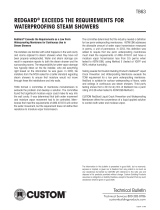
Airless Spray Tip Characteristics
It is important to remember that the orifice size, in conjunction
with the fan width size, determines the spray characteristics
of the tip.
Examples: As the orifice size increases, while maintaining the
same fan width size, the greater the volume of coating will be
applied to the same area.
FAN WIDTH -10" (25 cm)
Tip Size: 517 521 526
Conversely, the larger the fan width size, while maintaining the
same orifice size, will result in the same amount of material being
applied over a greater surface area.
ORIFICE SIZE -.017
Tip Size: 417 617 817
TIP WEAR
When beginning a project, choosing the right tip size and fan
width will determine how profitable you will be through both
coating consumption and production time. If the tip size being
used is wrong – by either choice or through wear – mil
thickness will be too heavy and the finish will be unprofessional.
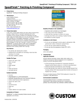
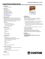
The spray pattern chart below demonstrates what happens as a
tip wears. As wear occurs, the pattern size decreases and the
orifice size increases. You will find that you have to make more
passes to cover the same area. There is no standard rate of tip
wear due to the variation of the abrasiveness of all coatings.
Replace your tips after 30-50 gallons (113-189 liters), it's one of
the most profitable things you can do.
New Old
In the case of applying RedGard
®
, it is recommended to use a tip
sized at 425 to 431. The use of any smaller orifice will result in the
material being atomized too much, or the tip will clog as a result
of the material being heavy bodied and high solids.
REDGARD
®
WATERPROOFING AND CRACK PREVENTION
MEMBRANE SPRAY APPLICATION SPECIFICATIONS
Technical Services 800-282-8786
custombuildingproducts.com
Technical Bulletin

Below are a few pictures of the application at two installations
in progress:
Typical spray application in hallways
Completed hall Cut in with trowel or roller
to avoid taping
Checking thickness Pump ready to go
with a wet film gauge
SPRAY PATTERN WIDTH
10" – 12"
(25 – 30 cm)
8"
(20 cm)
6"
(15 cm)
4"
(10 cm)
TIP SIZE
New
517
Worn to
419
Worn to
321
Worn to
223
FLOW RATE
.30 gpm
(1.1 lpm)
.40 gpm
(1.5 lpm)
.47 gpm
(1.7 lpm)
.57 gpm
(2.1 lpm)
FLOW RATE INCREASE
33% 57% 90%
Tip Size and Flow Rates
This application of RedGard
®
has proven to be very successful;
the key element is training on the equipment. The operator must
understand and be able to make adjustments to the system along
the way. If not, there will be loss of efficiency and time. The
second man on the team must keep the unit filled and assist the
operator with hose movement and equipment adjustments. This
is not a difficult operation to learn, and once a team is trained,
efficiency will increase.
Maintenance and cleaning of the equipment is essential. Periodic
cleaning of filters throughout the day and at final clean up will
eliminate problems with system clogs and down time.
Spray tip selection, pressure adjustments and hose length all
have a direct effect on the system. Replace tips after applying
every 20 units (100 gallons) of material (to maintain proper
spray patterns and coverage). The use of wet film gauges is also
recommended, to ensure that material application is not too thick
or thin.
TB35
REDGARD
®
WATERPROOFING AND CRACK PREVENTION
MEMBRANE SPRAY APPLICATION SPECIFICATIONS
Technical Services 800-282-8786
custombuildingproducts.com
Technical Bulletin

TB35
EQUIPMENT REQUIREMENTS
Speeflo PowerTwin 5500DI Direct Immersion Airless Spray Pump
or equal.
w
2.0 GPM with 5.5 HP Honda gas engine or equal.
w
1.25 GPM EXL-DC 115v Electric Motor or equal.
w
Titan Tool L70 In-Line Spray Gun w/3 foot extruded extension
and swivel head with appropriate housing for SC-5 reversible
spray tip.
w
Course (green) filter in the spray gun.
w
Titan Tool SC-5 Reversible Tip (.025-.029 for floor application).
w
Minimum 50’ and maximum 100’ of 3/8” Airless Hose.
APPLICATION
Follow all surface preparation instructions on Data Sheets.
Pump pressure: 1900psi to 2300psi depending on tip size
and length of hose.
Tip size: .025 to .029 (425, 427, or 429)
Reduction: None
It is recommended to stir material just prior to use.
To achieve the required film, the coating must be free from
pinholes and air bubbles; air bubbles will cause pinholes.
Apply coating in even passes to achieve 45 mils wet thickness.
Do not backroll coating.
Allow drying for a minimum of 24 hours prior to installation of tile,
stone or terrazzo.
SAFETY INFORMATION
Follow all health and safety precautions when applying
by spray. A 3M dual cartridge respirator and safety glasses
are recommended. See Technical Data Sheet and MSDS for
complete information.
RELATED PRODUCTS
RedGard
®
Waterproofing and Crack Prevention Membrane
REDGARD
®
WATERPROOFING AND CRACK PREVENTION
MEMBRANE SPRAY APPLICATION SPECIFICATIONS
Technical Services 800-282-8786
custombuildingproducts.com
Technical Bulletin
The information in this bulletin is presented in good faith, but no warranty,
express or implied, is given nor is freedom from any patent in as much as
any assistance furnished by CUSTOM
®
with reference to the safe use
and
disposal of its products provided without charge. Custom
®
Building Products
assumes no obligation or liability therefore, except to the extent that any such
assistance shall be given in good faith.
-
 1
1
-
 2
2
-
 3
3
-
 4
4


Custom Building Products LQWAF3-24 User guide
- Category
- Power fine-spray systems
- Type
- User guide
Ask a question and I''ll find the answer in the document
Finding information in a document is now easier with AI
Related papers
-
 Custom Building Products LQWAF1-75 Installation guide
-
Custom Building Products PMG50 Operating instructions
-
 Custom Building Products LQWAF1-75 User manual
-
Custom Building Products LQ50-35 Installation guide
-
 Custom Building Products RGSC1-2 Operating instructions
-
-
 Custom Building Products LQWAF1-75 Operating instructions
-
 Custom Building Products SF10 Installation guide
-
 Custom Building Products LLSLU30 Installation guide
-
 Custom Building Products CFT50 Installation guide


Other documents
-
WECO WE0780114 User manual
-
Titan Commander Owner's manual
-
-
Campbell Hausfeld Paint Sprayer AL2810 User manual
-
Wagner SprayTech 3000, 3500 User manual
-
LG Electronics 3600 User manual
-
-
Campbell Hausfeld AL2710 User manual
-
-