Page is loading ...

32
Operating Instructions
Instructions D’Utilisation
Manual de Instrucciones
DG201900CK
Notes
Notes
Notas
Please read and save these instructions. Read carefully before attempting to assemble, install, operate or maintain the product
described. Protect yourself and others by observing all safety information. Failure to comply with instructions could result in
personal injury and/or property damage! Retain instructions for future reference.
Operating Instructions and Parts Manual DG201900CK
Unpacking
When unpacking this product,
carefully inspect for any damage that
may have occurred during transit.
General Safety
Information
This manual contains information that is
very important to know and understand.
This information is provided for SAFETY
and to PREVENT EQUIPMENT PROBLEMS.
To help recognize this information,
observe the following symbols.
Danger
indicates
an imminently hazardous situation which,
if not avoided, will result in death or
serious injury.
Warning
indicates a
potentially hazardous situation which, if
not avoided, could result in death or
serious injury.
Caution
indicates
a potentially hazardous situation
which, if not avoided, may result in
minor or moderate injury.
Notice
indicates
important information, that if not
followed, may cause damage to tool.
The following safety precautions must
be followed at all times along with any
other existing safety rules.
1. Read all manuals included with this
product carefully. Be thoroughly
familiar with the controls and the
proper use of the equipment.
2. Only persons well acquainted with
these rules of safe operation should
be allowed to use this tool.
IN719900AV 6/07© 2007 Campbell Hausfeld/Scott Fetzer
See Warranty on page 10 for important information about commercial use of this product.
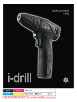
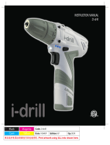
2-Finger
Trigger
Adjustable
Clutch Collar
Keyless Chuck
Horizontal
Barrel Level
Battery
Indicator
Magnetic
Tray
High/Low
Gear Switch
Vertical
Target
Level
Forward/Reverse
Button and
Trigger Lock
Bit Storage
Battery
Pack
Release
Soft Grip
REMINDER: Keep your dated proof of purchase for warranty purposes!
Attach it to this manual or file it for safekeeping.
Product Voltage
No-Load Max. Capacity
Battery Pack Battery charger
speed of chuck
Ø 3/8"
DG201900CK 19.2 V dc
0-360/0-1030
Ø 10 mm
DG201900BP DG029600AV
min
-1
Cordless Drill/Driver
and Charger
BUILT TO LAST
For parts, product & service information
visit www.chpower.com

31 Sp
DG201900CK
Garantía Limitada
1. DURACIÓN: 3 (tres) años a partir de la fecha de compra del comprador original del taladro. Las baterías están
garantizadas por 1 (un) año.
2. QUIEN OTORGA ESTA GARANTIA (EL GARANTE: Campbell Hausfeld / The Scott Fetzer Company 100 Production Drive,
Harrison, Ohio 45030 Teléfono: (800) 424-8936.
3. QUIEN RECIBE ESTA GARANTIA (EL COMPRADOR): El comprador original (que no sea un revendedor) del producto
Campbell Hausfeld.
4. QUÉ PRODUCTOS ESTÁN CUBIERTOS POR ESTA GARANTÍA: Cualquier herramienta a motor inalámbrica Campbell
Hausfeld distribuida o fabricada por el garante.
5. COBERTURA DE LA GARANTIA: Los defectos substanciales de material y fabricación que ocurran dentro del período
de validez de la garantía.
6. LO QUE NO ESTA CUBIERTO POR ESTA GARANTIA:
A. Las garantías implícitas, incluyendo aquellas de comercialidad E IDONEIDAD PARA FINES PARTICULARES,
ESTAN LIMITADOS A LO ESPECIFICADO EN EL PARRAFO DE DURACION. Si este producto es empleado para uso
comercial, industrial o para renta, la garantía será aplicable por noventa (90) días a partir de la fecha de compra.
En algunos estados no se permiten limitaciones a la duración de las garantías implícitas, por lo tanto, en tales casos
esta limitación no es aplicable.
B. CUALQUIER PERDIDA DAÑO INCIDENTAL, INDIRECTO O CONSECUENTE QUE PUEDA RESULTAR DE UN DEFECTO,
FALLA O MALFUNCIONAMIENTO DEL PRODUCTO CAMPBELL HAUSFELD. En algunos estados no se permite la
exclusión o limitación de daños incidentales o consecuentes, por lo tanto, en tales casos esta limitación o exclusión
no es aplicable
C. Cualquier falla que resulte de un accidente, abuso, negligencia o incumplimiento de las instrucciones de
funcionamiento y uso indicadas en el (los) manual(es) que se adjunta(n) al producto. Dichos accidentes, abusos por
parte del comprador, o falta de operar el producto siguiendo las instrucciones del manual de instrucciones
suministrado también debe incluir la desconexión o modificación de los instrumentos de seguridad. Si dichos
instrumentos de seguridad son desconectados, la garantía quedaría cancelada.
D. Los ajustes normales explicados en el(los) manual(es) suministrado(s) con el producto.
E. Artículos o servicio que se necesitan normalmente para el mantenimiento del producto, por ej.: contactos, asideros,
resortes, gatillos o cualquier otra pieza fungible no detallada específicamente. Estos artículos solamente estarán
cubiertos durante 90 (noventa) días a partir de la fecha de compra original.
7. RESPONSABILIDADES DEL GARANTE BAJO ESTA GARANTIA: Reparar o reemplazar, como lo decida el Garante,
los productos o componentes que estén defectuosos, se hayan dañado o hayan dejado de funcionar adecuadamente,
durante el período de validez de la garantía
8. RESPONSABILIDADES DEL COMPRADOR BAJO ESTA GARANTIA:
A. Suministrar prueba fechada de compra y la historia de mantenimiento del producto.
B. Llame a Campbell Hausfeld (800-424-8936) por sus opciones de servicio incluidas en la garantía. Los costos de flete
correrán por cuenta del comprador.
C. Seguir las instrucciones sobre operación y mantenimiento del producto, tal como se indica(n) en el (los) manual(es)
del propietario
9. CUANDO EFECTUARA EL GARANTE LA REPARACION O REEMPLAZO CUBIERTO BAJO ESTA GARANTIA: La reparación
o reemplazo dependerá del flujo normal de trabajo del centro de servicio y de la disponibilidad de repuestos.
Esta garantía limitada es válida sólo en los EE.UU., Canadá y México y otorga derechos legales específicos. Usted también
puede tener otros derechos que varían de un Estado a otro. o de un país a otro.
General Power Tool
Safety Warnings
Read all
safety
warnings and all instructions. Failure
to follow the warnings and
instructions may result in electric
shock, fire and/or serious injury.
SAVE ALL WARNINGS AND
INSTRUCTIONS FOR FUTURE
REFERENCE.
The term “power tool” in the warnings
refers to your battery-operated
(cordless) power tool.
1) Work area safety
a) Keep work area clean and
well lit. Cluttered or dark areas
invite accidents.
b) Do not operate power tools
in explosive atmosphere,
such as in the presence of
flammable liquids, gases or
dust. Power tools create sparks
which may ignite the dust or
fumes.
c) Keep children and bystanders
away while operating a
power tool. Distractions can
cause you to lose control.
2) Electrical Safety
a) Power tool plugs must match
the outlet. Never modify the
plug in any way. Do not use
any adapter plugs with
earthed (grounded) power
tools. Unmodified plugs and
matching outlets will reduce risk
of electric shock.
b) Avoid body contact with
earthed or grounded
surfaces, such as pipes,
radiators, ranges and
refrigerators. There is an
increased risk of electric shock if
your body is earthed or
grounded.
c) Do not expose power tools to
rain or wet conditions. Water
entering a power tool will
increase the risk of electric shock.
d) Do not abuse the cord. Never
use the cord for carrying,
2
Operating Instructions
pulling or unplugging the
power tool. Keep cord away
from heat, oil, sharp edges or
moving parts. Damaged or
entangled cords increase the
risk of electric shock.
e) When operating a power tool
outdoors, use an extension
cord suitable for outdoor
use. Use of a cord suitable for
outdoor use reduces the risk of
electric shock.
f) If operating a power tool in a
damp location is
unavoidable, use a residual
current device (RC) protected
supply. Use of an RCD reduces
the risk of electric shock.
g) Hold power tools by
insulated gripping surfaces
when performing an
operation where the cutting
tool may contact hidden
wiring or its own cord.
Contact with a “live” wire will
make exposed metal parts of the
tool “live” and shock the
operator.
h) If an extension cord is used,
make sure:
• That the size of the cord is at
least as specified in the chart
titled “Minimum Wire Size
(AWG) of Extension Cord for
Battery Charger.”
• That the pins on the plug of
the extension cord are the
same number, size, and shape
as those on the plug of the
charger.
• That the extension cord is
properly wired and in good
electrical condition.
• That the extension cord, if it is
to be used outdoors, is
marked with the suffix “W-A”
or “W”. This should follow
the cord type designation (e.g.
SJTW-A). Such a designation
indicates that it is acceptable
for outdoor use.
i) Recharge this battery-
operated tool only with the
charger specified for the
battery. A charger suitable
for one type of battery can
create a risk of fire when
used with another battery.
j) Use this battery-operated
tool only with its designated
battery pack. Use of any
other batteries may create a
risk of fire.
3) Personal safety
a) Stay alert, watch what you
are doing and use common
sense when operating a
power tool. Do not use a
power tool while you are
tired or under the influence
of drugs, alcohol or
medication. A moment of
inattention while operating
power tools may result in serious
personal injury.
b) Use personal protective
equipment. Always wear eye
protection. Protective
equipment such as dust mask,
non-skid safety shoes, hard hat,
or hearing protection used for
appropriate conditions will
reduce personal injuries.
c) Prevent unintentional
starting. Ensure the switch is
in the off-position before
connecting to power source
and/or battery pack, picking
up or carrying the tool.
Carrying power tools with your
finger on the switch or
energizing power tools that have
the switch on invites accidents.
Length of Cord in Feet 25 50 100 150
AWG Size of Cord 18 18 18 16
Minimum Wire Size (AWG) of Extension Cord for Battery Charger

30 Sp
Manual de Instrucciones
Mantenimiento
Limpieza
Todas las piezas de plástico deben
limpiarse con un paño húmedo.
NUNCA use solventes para limpiar
piezas de plástico. Podrían disolverse o
dañar el material de alguna otra
manera.
La herramienta no funciona
En caso de que la herramienta no
funcione, asegúrese de que la batería
esté cargada e instalada en el taladro.
Servicio a la batería
La batería que se proporciona con este
taladro se descargará sola y perderá
algo de su capacidad con el paso del
tiempo. Por lo tanto, si se almacena sin
usar durante un período de tiempo
prolongado, puede que sea necesario
recargarla antes de usarla. Para
obtener el mayor rendimiento de sus
baterías, se recomienda recargar la
batería cada 2 ó 3 meses y cuando se
recargue, se debe retirar la batería del
cargador después de 2 ó 3 horas de
carga.
Remoción / reemplazo del
portabrocas
Si fuera necesario reemplazar el
portabrocas, siga los pasos siguientes
para hacerlo:
• Retire la batería del taladro.
• Gire el collar de embrague hasta que
el símbolo de broca quede alineado
con la flecha que se encuentra en la
parte superior de la carcasa del
taladro.
• Abra completamente las mordazas
del portabrocas desatornillando el
manguito del portabrocas hacia la
izquierda (cuando se ve el
portabrocas desde su extremo).
• Ubique el tornillo izquierdo dentro
del portabrocas y con la punta de
destornillador adecuada quite este
tornillo girándolo hacia la derecha.
• Introduzca el brazo corto de una
llave hexagonal o Allen de 3/8 pulg.
dentro del portabrocas y apriete las
mordazas del portabrocas sobre las
partes planas de esta llave.
• Con un martillo o similar, golpee el
brazo largo de la llave con un golpe
seco de modo que el portabrocas
gire hacia la izquierda.
• Una vez que haya aflojado el
portabrocas, retire la llave y
desatornille el portabrocas de su
vástago.
• Para cambiar el portabrocas por
otro, invierta los pasos descritos
anteriormente. Siempre mantenga
las roscas del vástago, las roscas del
portabrocas y el tornillo sujetador
sin residuos.
Servicio
El servicio a esta herramienta debe
ser realizado únicamente por
personal calificado en reparación
y por un CENTRO DE SERVICIO
AUTORIZADO. El servicio o
mantenimiento realizados por
personas no calificadas puede
provocar riesgo de lesiones.
Para obtener información con relación
al funcionamiento o reparación de este
producto, sírvase llamar al
1-800-424-8936.
Para Ordenar Repuestos o Asistencia Técnica, Sírvase Llamar al
Distribuidor Más Cercano a Su Domicilio
S’il vous plaît fournir l’information suivante:
- Número del modelo
- Código impreso
- Descripción y número del repuesto según la lista de
repuestos
Número del
Descripción Repuesto
Dirija toda la correspondencia a:
Campbell Hausfeld
Attn: Parts Department
100 Production Drive
Harrison, OH 45030 U.S.A .
Cargador – 19,2V DG029600AV
Batería – 19,2V DG201900AV
Portabroca – 3/8 po DG029900AV
Tornillo de fijación SX173400AV
Caja DG030000AV
3
DG201900CK
General Power Tool
Safety Warnings
(Continued)
d) Remove any adjusting key or
wrench before turning the
power tool on. A wrench or a
key left attached to a rotating
part of the power tool may
result in personal injury.
e) Do not overreach. Keep
proper footing and balance
at all times. This enables better
control of the power tool in
unexpected situations.
f) Dress properly. Do not wear
loose clothing or jewelry.
Keep your hair, clothing and
gloves away from moving
parts. Loose clothes, jewelry or
long hair can be caught in
moving parts.
g) If devices are provided for
the connection of dust
extraction and collection
facilities, ensure these are
connected and properly used.
Use of dust collection can reduce
dust-related hazards.
h) CALIFORNIA PROPOSITION 65
You can create dust
when you cut,
sand, drill or grind
materials such as
wood, paint, metal,
concrete, cement,
or other masonry. This dust often
contains chemicals known to
cause cancer, birth defects, or
other reproductive harm. Wear
protective gear.
i)
This product or its power cord
contains lead, a chemical known
to the State of California to
cause cancer and birth defects or
other reproductive harm. Wash
hands after handling.
j) Some wood contains
preservatives which can be
toxic. Take extra care to
prevent inhalation and skin
contact when working with
these materials. Request and
follow all safety information
available from your material
supplier.
k)
Do not misuse this product.
Excessive exposure to vibration,
work in awkward positions, and
repetitive work motions can
cause injury to hands and arms.
Stop using any tool if discomfort,
numbness, tingling, or pain
occur, and consult a physician.
l) Always work in a well-
ventilated area. Wear an
OSHA-approved dust mask.
m) Keep hands away from
rotating parts.
n) Use clamps or another
practical way to secure the
workpiece to a stable
platform. Never hold work in
your hand, lap, or against
other parts of your body
when drilling.
o) Before using the battery
charger, read all instructions
on the charger, battery, and
product.
p) Do not attempt to
disassemble the battery or
remove any component
projecting from the battery
terminals. Fire or injury may
result.
4) Power tool use and care
a) Do not force the power tool.
Use the correct power tool for
your application. The correct
power tool will do the job better
and safer at the rate for which it
was designed.
b) Do not use the power tool if
the switch does not turn it on
and off. Any power tool that
cannot be controlled with the
switch is dangerous and must be
repaired.
c) Disconnect the plug from the
power source and/or the
battery pack from the power
tool before making any
adjustments, changing
accessories, or storing power
tools. Such preventive safety
measures reduce the risk of
starting the power tool
accidentally.
d) Store idle power tools out of
the reach of children and do
not allow persons unfamiliar
with the power tool or these
instructions to operate the
power tool. Power tools are
dangerous in the hands of
untrained users.
e) Maintain power tools. Check
for misalignment or binding
of moving parts, breakage of
parts and any other condition
that may affect the power
tool’s operation. If damaged,
have the power tool repaired
before use. Many accidents are
caused by poorly maintained
power tools.
f) Keep cutting tools sharp and
clean. Properly maintained
cutting tools with sharp cutting
edges are less likely to bind and
are easier to control.
g) Use the power tool,
accessories and tool bits etc.
in accordance with these
instructions, taking into
account the working
conditions and the work to
be performed. Use of the
power tool for operations
different from those intended
could result in a hazardous
situation.

29 Sp
Instrucciones
generales para
atornillar tornillos
(continuación)
•
Asegúrese de que la pieza de
trabajo esté asegurada.
Esto puede implicar sujetarla
en una prensa o sostenerla con
seguridad por otro medio de
sujeción. Una pieza de trabajo
floja puede girar y causar
lesiones corporales.
• Usando sus dedos, coloque la punta
del tornillo en el orificio piloto
y gírelo hacia la derecha para
comenzar a atornillarlo
perpendicularmente.
• Coloque la punta del destornillador
del tamaño adecuado sobre el
tornillo mientras ejerce presión
sobre el taladro, active el gatillo
para atornillar el tornillo en su lugar.
Es importante que el tornillo se
atornille perpendicularmente desde
el inicio, por lo tanto se debe aplicar
una presión perpendicular constante
para atornillar el tornillo
adecuadamente en su lugar. Si se
ejerce muy poca presión sobre el
taladro durante esta operación de
atornillado, puede que la punta del
destornillador no permanezca sobre
la cabeza del tornillo, esto podría
dañar o estropear el extremo del
tornillo.
• En cuanto el tornillo quede apoyado,
suelte el gatillo y levante el
destornillador de la cabeza del
tornillo. Si el taladro se desembraga
antes de atornillar el tornillo hasta la
profundidad deseada, retire el
taladro de la cabeza del tornillo y
aumente el valor del collar de
embrague. Luego repita el proceso
de atornillado.
• Se podrá usar un lubricante, como
jabón o cera, sobre las roscas de los
tornillos para atornillar con más
facilidad. Esto es particularmente
importante cuando se trabaja con
maderas duras.
• Generalmente los tornillos están
compuestos por una sección roscada,
una sección de espiga en la que no
hay roscas y la cabeza del tornillo.
En ocasiones es preferible taladrar
orificios/avellanados en una
operación, y hay diferentes brocas
de combinación (por ej. brocas para
orificios piloto/de paso, brocas para
orificios piloto/avellanados, etc.)
disponibles en las tiendas de
suministros locales para hacer estas
combinaciones.
Cómo atornillar tornillos para
madera
Además de las pautas proporcionadas
en las instrucciones generales de
atornillado, también se aplica lo
siguiente:
• Antes de atornillar en su lugar un
tornillo para madera, se recomienda
que se perfore un orificio piloto
(y un orificio avellanado si es
necesario). Consulte la tabla que
aparece a continuación para ver las
recomendaciones cuando se utilizan
tamaños comunes de tornillos.
Cómo atornillar tornillos
autorroscantes
Además de las pautas proporcionadas
en las instrucciones generales de
atornillado, también se aplica lo
siguiente:
• Antes de atornillar en su lugar el
tornillo autorroscante, taladre un
orificio piloto del tamaño
recomendado por el fabricante.
Coloque la punta del tornillo dentro
del orificio pretaladrado mientras
sostiene suavemente el tornillo en
posición perpendicular, comience a
atornillar lentamente el tornillo.
Una vez que se haya iniciado
adecuadamente, deje de sostener las
roscas del tornillo y termine de
atornillarlo. En cuanto el tornillo
quede apoyado, suelte el gatillo y
levante el taladro de la cabeza del
tornillo.
Cómo atornillar tornillos para
metales
Además de las pautas proporcionadas
en las instrucciones generales de
atornillado, también se aplica lo
siguiente:
• Antes de atornillar en su lugar el
tornillo para metales, taladre y
rosque un orificio del tamaño
recomendado por el fabricante.
Comience a atornillar con la mano
las primeras roscas del tornillo en el
orificio roscado y una vez que esté
perpendicularmente en su lugar,
deje de sostener el tornillo y
comience a atornillarlo lentamente
con el destornillador. Una vez que el
tornillo quede apoyado totalmente,
suelte el gatillo y levante el taladro
de la cabeza del tornillo.
Cómo quitar tornillos
Para quitar un tornillo de una pieza de
trabajo, siga los siguientes pasos:
• Coloque el collar de embrague
ajustable en su valor más alto y fije
el selector de velocidad en su valor
más bajo “1”.
• Instale la punta de destornillador
adecuada en el portabrocas del
taladro.
• Presione totalmente el botón de
retroceso (REV).
• Coloque la punta de destornillador
en la cabeza del tornillo y ejerciendo
suficiente presión sobre el taladro
como para que no zafe de la cabeza
del tornillo, encienda el taladro para
retirar el tornillo.
DG201900CK
4
General Power Tool
Safety Warnings
(Continued)
h) When the battery pack is not
in use, keep it away from
metal objects such as paper
clips, coins, keys, nails,
screws, or the like so there is
no risk of the battery
terminals being connected
(that is, “shorted”) together.
Shorting the battery terminals
together may cause sparks,
burns, a fire, a shock, or damage
to the battery.
i) Do not use if the chuck jaws
or other parts are cracked or
worn.
j) Verify the drill’s rotation
before starting to drill/drive,
so that it is correct for the
operation being performed.
k) Do not use the drill as a
router or try to elongate or
enlarge holes by twisting the
drill. Drill bits may break and
cause injury.
l) Each drill is equipped with a
chuck capable of handling
bits up to a certain size. For
the DG2019 drill, bits with
shaft diameters greater than
3/8" [10mm] should not be
used.
m) Ensure the switch is in the
off position before inserting
the battery pack. Inserting the
battery pack into power tools
that have the switch on invites
accidents.
n) Recharge the battery pack
only with the charger
supplied with this tool. A
charger that is suitable for one
type of battery pack may create
a risk of fire when used with
another battery pack.
o) Use this drill only with the
supplied battery pack or the
recommended replacement
pack as specified by the
manufacturer. Use of any other
battery packs may create a risk
of injury or fire.
p) Charge the battery pack in a
well-ventilated area. Do not
allow any object to cover the
charger and/or battery pack
while charging.
q) Do not operate the battery
charger if its plug or cord has
been damaged. If these
components are damaged,
have them replaced
immediately by a qualified
repair person.
r) Do not operate the charger if
it has been dropped, received
a sharp blow, or otherwise
been damaged. If damaged,
have it serviced by a
qualified repair person.
s) Make sure the cord is located
so that it will not be stepped
on, tripped over, or
otherwise subjected to
damage or stress.
t) Do not store the battery
charger or battery pack in
locations where the
temperature may reach or
exceed 120°F [49°C], such as
in a metal tool shed or in a
car during the summer. This
can lead to deterioration of
these components.
u) For optimal charging of the
battery pack, charging should
take place in temperatures
ranging from 32°F to 86°F
[0°C to 30°C]. Charging the
battery pack outside this
recommended range can
adversely affect the battery’s
performance.
v) Do not charge the battery
pack in damp or wet
conditions.
w) Do not charge the battery
pack if it feels hot to the
touch. Wait for it to cool.
x) Since this tool is equipped
with nickel-cadmium
batteries, the battery pack
must be recycled or disposed
of in an environmentally
sound manner. Check with
your county’s Public Works
Department for information
on recycling nickel-cadmium
batteries. Prior to disposal,
insulate the metal battery
pack terminals by covering
them securely with heavy
insulating tape in order to
prevent any possible
shorting.
y) Do not incinerate the
battery pack as it may
explode in a fire.
5) Service
Have your power tool
serviced by a qualified repair
person using only identical
replacement parts. This will
ensure that the safety of the
power tool is maintained.
Tool Operation
The power source for this drill comes
from the supplied battery packs. It is
important that the user understand
the following in order to get the most
of the battery pack and the battery
charger.
Installing / Removing the Battery
Pack to / from the Drill
• In order to install the battery pack to
the drill, insert the tower potion of
the pack into the drill handle. Push
the battery pack until you hear the
pack latching to the drill.
• In order to remove the battery pack
from the drill, depress both of the
circular (ribbed) buttons on the pack
and then pull the pack from the
drill.
Operating Instructions

28 Sp
Manual de Instrucciones
Instrucciones
generales de
taladrado
(continuación)
• Cuando la broca haya penetrado la
pieza de trabajo por completo y esté
girando libremente, retírela de la
pieza de trabajo mientras el motor
aún está en funcionamiento y luego
apague el taladro.
Cómo perforar madera
Además de las pautas proporcionadas
en las instrucciones generales de
taladrado, también se aplica lo
siguiente:
• Cuando taladre madera más blanda,
generalmente se usan velocidades
más altas.
• Cuando taladre madera usando una
broca helicoidal, retírela
frecuentemente del orificio para
quitar las láminas que se acumulan
en las estrías. Esto ayuda a evitar el
sobrecalentamiento y quemar el
material a la vez que acelera el
proceso de taladrado.
• Si se utiliza un bloque de apoyo para
que la parte trasera de la pieza de
trabajo no se astille, sujételo en su
lugar en forma segura. Si no se usa
un bloque de apoyo con las brocas
de paleta o brocas de campana,
libere la presión ejercida sobre el
taladro en cuanto la punta de la
broca perfore la pieza de trabajo.
Quite la broca y usando el orificio de
salida, vuelva a colocar la broca en el
lado opuesto de la pieza de trabajo y
termine la operación de taladrado.
Taladrado en metal
Además de las pautas proporcionadas
en las instrucciones generales de
taladrado, también se aplica lo
siguiente:
• Use únicamente brocas para alta
velocidad, de buena calidad y
afiladas cuando taladre metal.
• Cuando se taladra metal,
generalmente se usan velocidades
más bajas. Cuanto más duro sea el
material, más baja debe ser la
velocidad de taladrado.
• Comience a taladrar con una
velocidad baja y aumente
paulatinamente la velocidad a
medida que el taladro corta.
• Cuando taladre un orificio grande,
es más fácil perforar primero un
orificio más pequeño (piloto) y
después agrandarlo al tamaño
necesario.
• El uso de un lubricante, como el
aceite, en la punta del taladro ayuda
a mantener la broca fría, aumenta la
acción de perforación y prolonga la
vida útil de la broca.
Instrucciones
generales para
atornillar tornillos
Se
deben usar gafas de seguridad
durante las operaciones de
atornillado.
Siempre
esté
atento y contrarreste la acción
giratoria del taladro. Cuando se
atornillen tornillos siempre debe
usarse un asimiento firme. El no
hacerlo podría ocasionarle lesiones
corporales.
• Perfore primero un orificio piloto
del tamaño recomendado por el
fabricante del tornillo antes de
introducir el tornillo en su lugar.
• Ajuste el collar del portabrocas del
taladro de modo que el cuerpo del
taladro apunte al valor de torsión
deseado. Un número más bajo hará
que el taladro se desembrague más
pronto, es decir, no atornillará el
tornillo en la pieza de trabajo hasta
la profundidad que lo haría si se
usara un valor más alto en el collar
de embrague.
• Ajuste el selector de velocidad al
valor de velocidad bajo “1”.
• Instale la punta adecuada del
destornillador y asegúrese que esta
punta esté fijada con seguridad en
el portabrocas.
• Asegúrese de que el botón de
avance (FWD) está totalmente
presionado. Esto hará que el taladro
gire en la dirección de avance,
es decir, hacia la derecha cuando
se mira desde el punto de vista del
usuario.
RECOMENDACIONES PARA ATORNILLAR TORNILLOS PARA MADERA
TAMANO DIÁMETRO DE BROCAS
DEL PARA ORIFICIOS PILOTO ORIFICIO PUNTAS DE DESTORNILLADOR
TOMILLO (MADERA BLANDA) (MADERA DURA) PILOTO AVELLANADO PUNTA DE PALETA PUNTA PHILLIPS
#6 1/16" (0.063") 5/64" (0.078") 9/64" (0.141") 3/16" #2
#8 5/64" (0.078") 3/32" (0.094") 11/64" (0.172") 1/4" #2
#10 3/32" (0.094") 7/64" (0.109") 3/16" (0.188") 5/16" #2 or #3*
#12 7/32" 0.219") 1/8" (0.125") 7/32" (0.219") 3/8" #3
* Algunos estilos de cabeza en este tamaño requieren una punta Phillips Nº2 y otros Nº3.
Tool Operation
(Continued)
Charging the Battery Pack
Installing/Removing the Battery Pack
from the Battery Charger
• The battery pack is designed
so that it can only fit into the
charger in one orientation,
therefore, there is no reason
to force the pack into the
charger. To install the battery
pack in the charger, insert the
tower end of the pack into
the charger. The protruding
rib on one side of the battery
pack should be aligned with
the notch in the battery
charger. Once this alignment
is done, lightly push the
battery pack until it bottoms
out in the charger.
• To remove the battery pack
from the charger, simply pull
the battery straight out of the
battery charger.
Initial Charging
Before using this drill for the first
time, charge the battery fully. This
can be done by first plugging the
battery charger into a 120V (60 Hz)
power supply and then inserting the
battery fully into the charger, noting
that the battery pack rib is oriented
so that it fits into the notch of the
battery charger. When the battery
pack is pressed slightly so that the
pack bottoms out in the charger, the
red charger light should then
illuminate. This indicates that the
battery is being charged. Once the
pack is fully charged, the green
charger light should illuminate. This
charging process should take
approximately one hour.
Additional Charging Notes
• During normal use, the
battery pack will eventually
lose its capacity and when this
happens, there will be a
noticeable difference in the
drill’s performance. It is at this
point that the battery pack
approaches its discharged
state and needs to be
recharged. If the pack is
warm-hot to touch, let the
battery pack cool down
before placing it in the
charger. This will allow the
pack to accept a full charge
whereas it might not do so if
inserted in the charger in an
elevated-temperature state.
• With the type of battery
supplied with this drill, that is
Ni-Cd or Nickel Cadmium type,
it is best that they are charged
when close to its discharged
state. This is the point where
there is a noticeable
difference in the performance
of the drill. If the pack is
placed in the charger before it
reaches this state, there is a
possibility that the
capacity/life of the battery
pack may not be optimized. It
is also important to note that
a battery pack should not be
discharged past the
performance-noticeable state
mentioned above as this
might irreversibly damage the
battery pack.
• Lastly in order to get the most
out of your battery pack, it is
highly recommended that the
packs not remain in the
charger for more than 3
hours. So once fully-charged
(indicated by the green
charger light illuminating), it
is best to remove the battery
pack at or near that point.
Forward/Reverse Button
This drill is equipped with a
forward/reverse (red) button which is
used to change the direction of
rotation of the drill chuck/bit. It is
recommended that the user check the
direction of rotation prior to
performing the work. If the FWD
button is firmly depressed from the
right side of the drill when the user
holds it, the rotation of the drill will be
in the forward direction, or clockwise
when viewing the chuck from a user
viewpoint. This is the recommended
rotational direction for drilling holes
or driving screws. By firmly depressing
the REV button (on the left side of the
tool), the rotation of the drill will be
counterclockwise. This direction of
rotation is recommended for removing
screws. It is also useful if a drill bit has
been stuck when drilling in the
forward direction.
Do not attempt to change the rotation
unless the drill chuck is completely
stopped. Failure to do so can damage
the tool.
If the FWD/REV button is centered in
the drill housing, that is, not fully
depressed to either side, then the
switch trigger should be locked in the
“OFF” position.
Variable-Speed Switch Trigger
This drill is equipped with a variable-
speed switch. By applying more
pressure to the (red) switch trigger, the
speed of the drill will increase.
Releasing pressure will slow the drill.
This accurate speed control allows the
user to slowly start drilling a hole
without center-punching, or slowly
start driving screws, before increasing
the operational rate.
5
Charger and Battery
DG201900CK

27 Sp
Funcionamiento de
la herramienta
(continuación)
Soporte magnético para tornillos
Este taladro/destornillador está
equipado con un imán en la parte
superior del mismo, debajo del símbolo
de imán en herradura. Esto es útil para
guardar tornillos cuando se realiza un
trabajo repetitivo.
Luces indicadoras del medidor de
carga de la batería
Este taladro/destornillador está
equipado con un medidor de carga de
la batería. Está ubicado en la parte
superior del taladro y se compone de
tres luces verdes y un botón negro.
Para verificar el estado de la batería,
presione el botón negro cuando el
taladro esté apagado. Si se iluminan
las tres luces verdes, esto indica una
batería con carga completa o casi
completa. Si solo se ilumina una luz
verde, la batería está próxima al punto
en el que debería recargarse. Si no se
ilumina ninguna luz, la batería
necesita ser recargada.
Colocación / remoción de brocas
• Para fijar la broca en el taladro,
mueva el botón de avance y
retroceso (FWD/REV) a su posición
central y gire el anillo de embrague
hasta el símbolo de broca del
taladro. Gire el manguito del
portabrocas hacia la izquierda
(mirando desde el extremo del
portabrocas) hasta que las mordazas
del portabrocas se abran un poco
más que el diámetro de la broca a
colocar. Coloque una broca limpia
hasta las estrías de la broca (para
brocas más pequeñas) o hasta donde
llegue para brocas grandes. Cierre el
portabrocas girando el manguito
hacia la derecha y ajuste a mano en
forma segura.
• Para quitar la broca del taladro,
mueva el botón de avance y
retroceso (FWD/REV) a su posición
central y gire el anillo de embrague
hasta el símbolo de broca del
taladro. Gire el manguito del
portabrocas hacia la derecha
(mirando desde el extremo del
portabrocas) hasta que las mordazas
del portabrocas se abran un poco
más que el diámetro de la broca
y luego retire la broca.
No use la corriente del taladro
para aflojar ni ajustar la broca
mientras sostiene el portabrocas.
Al girar, el portabrocas causará
quemaduras por fricción y lesiones
en la mano.
Con este taladro se incluyen
incorporadas puntas de destornillador
Phillips o de paleta y se pueden
instalar fácilmente como se explicó
anteriormente. Éstas son
particularmente útiles para atornillar
y quitar tornillos.
Instrucciones
generales de
taladrado
Se
deberán
usar gafas de seguridad durante
las operaciones de taladrado.
Siempre esté atento y contrarreste
la acción giratoria del taladro.
Cuando se taladre siempre debe
usarse un asimiento firme. El no
hacerlo podría ocasionarle lesiones
corporales.
• Ajuste el collar del portabrocas del
taladro de modo que la flecha en el
cuerpo del taladro apunte hacia el
símbolo de la broca en el collar del
portabrocas.
• Ajuste el selector de velocidad a la
velocidad deseada. Generalmente
cuanto más duro sea el material a
taladrar, más lenta es la velocidad
recomendada.
• Asegúrese de que la broca del
taladro esté fijada con seguridad en
el portabrocas.
• Asegúrese de que el botón de
avance (FWD) esté totalmente
presionado. Esto hará que el taladro
gire en la dirección de avance, es
decir, hacia la derecha cuando se
mira desde el punto de vista del
usuario.
•
Asegúrese de que la pieza de
trabajo esté asegurada. Esto
puede implicar sujetarla en una
prensa o sostenerla con
seguridad por otro medio de
sujeción. Una pieza de trabajo
floja puede girar y causar
lesiones corporales.
• Ubique el centro del orificio a
taladrar y usando un punzón, haga
una pequeña muesca en la pieza de
trabajo.
• Coloque la punta de la broca del
taladro en esta marca, sostenga el
taladro perpendicular a la pieza de
trabajo, aplique una presión
constante y accione el interruptor
del taladro.
•
Continúe aplicando una presión
firme y pareja mientras taladra.
El aplicar demasiada presión
puede causar que la broca se
recaliente y/o se quiebre, lo cual
podría provocar lesiones
corporales o daños a las brocas.
Una presión demasiado suave
evitará que la broca perfore la
pieza de trabajo.
• Si el taladro pierde sustentación o se
atasca en el orificio, suelte el gatillo
de inmediato. No continúe
accionando el gatillo en la dirección
de avance para liberar la broca
atascada, ya que esto dañará el
motor. Quite la broca de la pieza de
trabajo y determine la causa de la
pérdida de sustentación o
atascamiento antes de volver a
comenzar. Si se dificulta la remoción
de la broca de la pieza de trabajo,
entonces presione totalmente el
botón de retroceso (REV) y accione
el interruptor para quitar la broca.
Luego presione totalmente el botón
de avance (FWD) antes de retomar el
trabajo de taladrado.
• Cuando la broca esté a punto de
salir por el otro lado del material
que se está taladrando, reduzca la
presión sobre el taladro para evitar
astillar la madera o que pierda
sustentación en una pieza de trabajo
de metal.
DG201900CK
Tool Operation
(Continued)
Two-speed gearing
In addition to the variable-speed
switch, this drill is also equipped with a
two-speed gearbox. The low gear
(setting “1”) provides high-torque and
slower drilling speeds for heavy-duty
work or for driving screws. The high
gear (setting “2”) provides faster
speeds which is particularly useful for
drilling into softer materials. To
change to the high-speed setting, push
the (red) speed selector knob fully
forward. For the low-speed setting,
move the speed-selector knob fully
toward the rear of the drill. It is
important that this knob be positioned
fully forward or fully back, anywhere
in between can cause damage to the
drill.
If the drill has been actuated but the
chuck is not rotating, fully release
pressure on the switch actuator and
then slide the gear actuator to its
desired setting.
Electrical Brake
This drill is equipped with an electrical
brake which is used to stop the chuck
quickly. This is useful when the job
calls for repetitive driving or removal
of screws. This is activated by merely
releasing the switch actuator while the
drill is rotating. When the electric
brake is actuated, it is common to see
momentary arcing within the drill
itself.
Adjustable Clutch
This drill/driver features 16 clutch
settings. Output torque will increase as
the clutch collar is rotated from 1 to
15. The drill bit position locks the
clutch in order to permit heavy-duty
drilling and driving work. It also allows
bits to be changed quickly and easily in
the keyless chuck. This adjustable
clutch is particularly useful when
driving screws. A lower clutch setting
will ratchet sooner than a high-clutch
setting, that is, it will limit how far a
screw is driven. When driving screws, it
is best to start at a lower clutch setting
and adjust this collar upwards until the
screw is set to the desired depth.
Bubble Levels
This drill/driver is equipped with two
bubble levels in order to make it easier
for the user to drill squarely. There is a
horizontal level on top of the drill and
in order to drill/drive horizontally, the
bubble on this particular level should
be centered between the two level
lines. For those jobs where the user
wants to drill straight up-and-down,
there is another level on the back side
of the drill for that particular purpose.
For vertical drilling, the center of the
bubble should be at the intersection of
the crosshairs.
Magnetic Screw Holder
This drill/driver is equipped with a
magnet on top of the drill, underneath
the horseshoe magnet symbol. This is
useful for storing screws when doing
repetitive work.
Battery Fuel Gauge Indicator Lights
This drill/driver is equipped with a
battery fuel gauge. This is positioned
on top of the drill and is composed of
three green lights and a black button.
In order to check the state of the
battery pack, depress the black button
when the drill is OFF. If three of the
green lights illuminate, this indicates a
fully-charged or nearly charged
battery pack. If only one green light
illuminates, the battery pack is nearing
that point where it should be
recharged. If no lights illuminate, the
battery pack needs to be recharged.
Inserting / Removing Bits
• In order to clamp a bit in the drill,
move the FWD/REV button to its
center position and rotate the clutch
ring to the drill bit symbol. Rotate
the chuck sleeve counterclockwise
(when viewing from the chuck end)
until the chuck jaws are opened
slightly more than the diameter of
the bit to be inserted. Insert a clean
bit up to the drill bit flutes (for
smaller bits) or as far as it will go for
large bits. Close the chuck by
rotating the chuck sleeve clockwise
and securely tighten by hand.
• In order to remove the bit from the
drill, move the FWD/REV button to
its center position and rotate the
clutch ring to the drill bit symbol.
Rotate the chuck sleeve clockwise
(when viewing from the chuck end)
until the chuck jaws are opened
slightly more than the diameter of
the bit and then remove the bit.
Do not
use the
power of the drill to loosen or tighten
the bit while holding the chuck. The
spinning chuck will cause friction burn
and hand injury.
Phillips and slotted screw driver bits
are included onboard with this drill
and can be easily installed as
previously noted. These are particularly
useful for driving/removing screws.
General Drilling
Instructions
Safety
glasses
must be worn during drilling
operations.
Always
be alert
and brace yourself against the twisting
action of the drill. A firm hold should
always be administered when drilling.
Failure to do so may result in bodily
injury.
• Adjust the drill’s chuck collar so that
arrow on the drill body points to the
drill bit symbol on the chuck collar.
• Set the speed selector to the desired
setting. Typically the harder the
material being drilled into, the
slower the recommended speed.
• Insure that the drill bit is securely
gripped in the chuck.
• Make sure that the FWD button is
fully depressed. This should make
the drill rotate in the forward
direction, that is, clockwise as
viewed from the user’s vantage
point.
6
Operating Instructions

26 Sp
Manual de Instrucciones
Funcionamiento de
la herramienta
(continuación)
• Con el tipo de batería
proporcionada con este taladro,
es decir del tipo Ni-Cd o níquel-
cadmio, es mejor cargar la
batería cuando está casi
totalmente descargada. Este es el
momento en el que hay una
diferencia notoria en el
rendimiento del taladro. Si se
coloca la batería en el cargador
antes de que llegue a este
estado, existe la posibilidad de
que no se optimice la
capacidad/vida útil de la batería.
También es importante tener en
cuenta que una batería no debe
descargarse más que cuando
llega al estado de rendimiento
notorio mencionado
anteriormente ya que esto puede
provocar un daño irreversible en
la batería.
• Por ultimo, para obtener el
mejor rendimiento de su batería,
se recomienda encarecidamente
no dejar las baterías en el
cargador durante más de 3
horas. Por lo tanto una vez que
alcancen su carga completa (que
se indica cuando se enciende la
luz verde en el cargador), es
mejor retirar la batería en ese
momento o en un momento
próximo.
Botón de avance/retroceso
Este taladro está equipado con un
botón de avance/retroceso (rojo) que
se usa para cambiar la dirección de
rotación de la broca del taladro. Se
recomienda que el usuario verifique el
sentido de la rotación antes de realizar
el trabajo. Si el botón de avance (FWD)
se presiona firmemente desde el lado
derecho del taladro cuando el usuario
lo está sosteniendo, la rotación del
taladro será en la dirección de avance,
o hacia la derecha cuando se mira el
portabrocas desde el punto de vista del
usuario. Esta es la dirección de rotación
recomendada para taladrar orificios o
atornillar tornillos. Al presionar
firmemente el botón de retroceso
(REV), ubicado en el lado izquierdo de
la herramienta, la rotación del taladro
será hacia la izquierda. Esta dirección
de rotación se recomienda para quitar
tornillos. También es útil si se ha
atascado una broca cuando se
taladraba en la dirección de avance.
No intente cambiar la rotación a
menos que el portabrocas se haya
detenido por completo. El no hacerlo
puede dañar la herramienta.
Si el botón de avance y retroceso
(FWD/REV) está centrado en la carcasa
del taladro, es decir que no está
presionado totalmente para ninguno
de los dos lados, entonces el gatillo
debe estar bloqueado en la posición de
apagado “OFF”.
Gatillo interruptor de velocidad
variable
Este taladro está equipado con un
interruptor de velocidad variable.
Al aplicar más presión al gatillo
interruptor (rojo), la velocidad del
taladro aumenta. Al disminuir la
presión se reducirá la velocidad del
taladro. Este preciso control de
velocidad permite al usuario comenzar
a taladrar un orificio lentamente sin
tener que hacer un orificio inicial con
el punzón, o comenzar lentamente a
atornillar tornillos antes de aumentar
la velocidad de funcionamiento.
Engranajes de dos velocidades
Además del interruptor de velocidad
variable, este taladro también está
equipado con una caja de engranajes
de dos velocidades. La posición baja
(ajuste “1”) proporciona torsión alta y
velocidades más bajas de perforación
para trabajo pesado o para atornillar
tornillos. La posición alta (ajuste “2”)
proporciona velocidades más altas y es
particularmente útil para perforar
materiales más blandos. Para cambiar
al valor de velocidad alta, empuje la
perilla de selección de velocidad (roja)
totalmente hacia adelante. Para el
valor de velocidad baja, mueva la
perilla de selección de velocidad
totalmente hacia la parte trasera del
taladro. Es importante que la perilla
quede colocada totalmente hacia
adelante o hacia atrás, cualquier otra
posición entre estos dos extremos
puede causar daños al taladro.
Si se accionó el taladro pero el
portabrocas no está girando, suelte
toda la presión del interruptor y luego
deslice el accionador del interruptor a
la posición deseada.
Freno eléctrico
Este taladro está equipado con un
freno eléctrico que se usa para detener
rápidamente el portabrocas. Esto es
útil cuando el trabajo requiere
taladrado o remoción de tornillos en
forma reiterada. Esto se activa
simplemente soltando el accionador
del interruptor mientras está girando
el taladro. Cuando se activa el freno
eléctrico, es común observar un arco
eléctrico momentáneo dentro del
propio taladro.
Embrague ajustable
Este taladro/destornillador cuenta con
16 configuraciones de embrague. La
torsión de salida aumentará a medida
que el collar de embrague se gire de 1
a 15. La posición de la broca del
taladro traba el embrague para
permitir una perforación para trabajos
pesados y para trabajar con el
destornillador. También permite
cambiar las brocas rápida y fácilmente
en el portabrocas sin llave.
Este embrague ajustable es
particularmente útil cuando se
atornillan tornillos. Un valor más bajo
del embrague desembragará más
pronto que un valor más alto del
embrague, es decir, limitará la
profundidad a la que se atornille el
tornillo. Cuando se atornillan tornillos,
es mejor comenzar con un valor más
bajo del embrague y ajustar este collar
hacia arriba hasta que el tornillo
llegue a la profundidad deseada.
Niveles de burbuja
Este taladro/destornillador está
equipado con dos niveles de burbuja
para hacer que sea más fácil para el
usuario taladrar perpendicularmente.
Tiene un nivel horizontal en la parte
superior del taladro para
taladrar/atornillar horizontalmente,
la burbuja de este nivel en particular
debe estar centrada entre las dos
líneas del nivel. Para aquellos trabajos
en los que el usuario desee taladrar
verticalmente hacia arriba y hacia
abajo hay otro nivel en la parte trasera
del taladro para ese uso en particular.
Para el taladrado vertical, el centro de
la burbuja debería estar en la
intersección la cruz.
General Drilling
Instructions
(Continued)
• Make
sure that the workpiece is secured
This might entail clamping it in a vise
or held securely by other clamping
means A loose workpiece may spin
and cause bodily injury.
• Locate the center for the hole to be
drilled and using a center punch,
make a small dent in the workpiece.
• Place the tip of the drill bit in this
dent, hold the drill square to the
workpiece, apply steady pressure,
and actuate the drill’s switch.
•
Continue to apply steady, even
pressure while drilling. Applying too
much pressure may cause the drill bit
to overheat and/or break, resulting
in bodily injury or damaged drill bits
Too little pressure will keep the bit
from cutting into the workpiece.
• If the drill stalls or becomes jammed
in the hole, release the switch
trigger immediately Do not keep
actuating the switch trigger in the
forward direction in order to free
the bit from its jammed condition,
for this will damage the motor
Remove the drill bit from the
workpiece and determine the cause
of stalling or jamming before
beginning again. If it is troublesome
to remove the bit from the
workpiece, then fully-depress the
REV button and actuate the switch
to remove the bit. Then fully depress
the FWD button before resuming
the drilling operation.
• When the bit is at the point where it
nearly breaks through the material
being drilled, reduce the pressure on
the drill in order to avoid splintering
the wood or stalling in a metal
workpiece.
• When the drill bit has completely
penetrated the workpiece and is
spinning freely, withdraw it from
the workpiece while the motor is
still running, and then turn off the
drill.
Drilling Wood
In addition to the guidelines given in
the General Drilling Instructions, the
following also apply:
• When drilling into softer wood,
higher speed settings are generally
used.
• When drilling into wood using a
twist drill bit, frequently withdraw it
from the hole in order to clear away
chips which build up in the flutes.
This helps prevent overheating and
burning the material while speeding
up the drilling process.
• If a backing block is used to keep the
back of the workpiece from
splintering, clamp it securely in
place. If a backing block is not use
with spade bits or hole saws, ease up
the pressure exerted on the drill as
soon as the bit point breaks through
the workpiece. Remove the bit and
using the breakthrough hole,
reposition the bit on the opposite
side of the workpiece and finish the
drilling operation.
Drilling in Metal
In addition to the guidelines given in
the General Drilling Instructions, the
following also apply:
• Use only good quality, sharp, high-
speed drill bits when drilling into
metal.
• When drilling into metal, lower
speed settings are generally used.
The harder the material, the slower
the drilling speed should be.
• Start drilling with a slow speed and
gradually increase the speed as the
drill cuts.
• When drilling a large hole, it is
easier to first drill a smaller (pilot)
hole and then enlarge it to the
required size.
• The use of a lubricant, such as oil, on
the drill point helps to keep the bit
cool, increases the drilling action,
and prolongs bit life.
7
DG201900CK

25 Sp
Advertencias de
seguridad generales
para herramientas
eléctricas
(continuación)
s) Asegúrese de que el cable
esté ubicado de tal manera
que nadie lo pise ni se
tropiece con él, y que no esté
sujeto de alguna otra manera
a algún daño o tensión.
t) No guarde el cargador ni la
batería en lugares donde la
temperatura pueda alcanzar
o exceder los 120ºF (49ºC),
como un cobertizo para
herramientas de metal o un
automóvil en verano. Esto
puede provocar el deterioro
de estos componentes.
u) Para lograr una carga óptima
de la batería, la carga se debe
realizar a temperaturas
entre 32°F y 86°F (0°C a 30°C).
El cargar la batería fuera de
este rango recomendado
puede afectar el rendimiento
de la batería de manera
adversa.
v) No cargue la batería en
lugares mojados ni húmedos.
w) No cargue la batería si se
siente caliente al tacto.
Espere que se enfríe.
x) Como esta herramienta está
equipada con baterías de
níquel-cadmio, la batería
debe reciclarse o desecharse
de manera que no dañe el
medio ambiente. Consulte al
Departamento de Obras
Públicas de su condado para
obtener información sobre
cómo reciclar baterías de
níquel-cadmio. Antes de
desecharla, aísle los
terminales metálicos de la
batería cubriéndolos en forma
segura con cinta aisladora
resistente para evitar un
posible cortocircuito.
y) No incinere la batería ya que
podría explotar en el fuego.
5) Servicio
Haga que una persona
calificada en reparación le
realice el servicio a su
herramienta eléctrica usando
únicamente piezas de repuesto
idénticas. Esto asegurará que se
mantenga la seguridad de la
herramienta eléctrica.
Funcionamiento de
la herramienta
La fuente de energía de este taladro
proviene de las baterías que se
proporcionan. Es importante que el
usuario comprenda lo siguiente a fin
de obtener el mayor rendimiento de la
batería y del cargador de la batería.
Instalación / Remoción de la
batería del taladro
• Para instalar la batería en el
taladro, introduzca la porción
protuberante de la batería dentro
del mango del taladro. Empuje la
batería hasta que escuche que la
misma queda enganchada en el
taladro.
• Para retirar la batería del taladro,
presione los dos botones circulares
(estriados) que se encuentran en la
batería y luego tire de la batería
para separarla del taladro.
Carga de la batería
Instalación / Remoción de la batería del
cargador de batería
• La batería está diseñada para que
únicamente calce en el cargador
en una sola orientación, por lo
tanto, no hay ningún motivo para
forzar la batería dentro del
cargador. Para instalar la batería
en el cargador, introduzca la
parte protuberante de la batería
dentro del cargador. La saliente
en uno de los lados de la batería
debe quedar alineada con la
muesca en el cargador de la
batería. Una vez que se realiza
esta alineación, empuje
suavemente la batería hasta que
toque el fondo en el cargador.
• Para retirar la batería del
cargador, simplemente tire de la
batería en dirección vertical hacia
afuera del cargador de batería.
Carga inicial
Antes de usar el taladro por primera
vez, cargue la batería por completo.
Para hacer esto enchufe primero el
cargador de la batería en un
suministro de corriente de 120V (60
Hz) e introduzca la batería
totalmente dentro del cargador,
prestando atención a que la saliente
de la batería quede orientada de
modo que calce en la muesca del
cargador de la batería. Cuando se
presiona suavemente la batería para
que la misma toque el fondo del
cargador, la luz roja del cargador
debería iluminarse. Esto indica que
la batería se está cargando. Una vez
que la batería esté totalmente
cargada, se debería iluminar la luz
verde del cargador. Este proceso de
carga debería llevar
aproximadamente una hora.
Notas adicionales sobre la carga
• Durante el uso normal, la batería
perderá eventualmente su
capacidad y cuando esto suceda,
habrá una diferencia notoria en
el rendimiento del taladro. Es en
este momento que la batería
está casi descargada y debe
volver a cargarse. Si la batería
está tibia o caliente al tacto, deje
que se enfríe antes de colocarla
en el cargador. Esto permitirá
que la batería acepte una carga
completa mientras que no podrá
hacerlo si se introduce en el
cargador mientras tiene una
temperatura elevada.
DG201900CK
Carga Rápida y Batería
General Driving
Screws Instructions
Safety
glasses
must be worn during driving
operations.
Always
be alert
and brace yourself against the twisting
action of the drill. A firm hold should
always be administered when driving
screws. Failure to do so may result in
bodily injury.
• Drill a pilot hole of a size
recommended by the screw
manufacturer prior to driving the
screws in place.
• Adjust the drill’s chuck collar so that
arrow on the drill body points to the
desired torque setting. A lower
number will cause the drill to ratchet
sooner, that is, it will not drive the
screw into the workpiece as far as if
a higher clutch collar setting is used.
• Set the speed selector to the low
speed “1” setting.
• Install the proper screwdriver bit and
insure that this bit is securely
gripped in the chuck.
• Make sure that the FWD button is
fully depressed. This should make
the drill rotate in the forward
direction, that is, clockwise as
viewed from the user’s vantage
point.
•
Make
sure that the workpiece is secured.
This might entail clamping it in a vise
or held securely by other clamping
means. A loose workpiece may spin
and cause bodily injury.
• Using one’s fingers, place the tip of
the screw in the pilot hole and turn
clockwise so as to start the screw
squarely.
• Place a properly-sized screwdriver bit
on the screw and while exerting
pressure on the drill, actuate the
switch trigger to drive the screw in
place. It is important that the screw
be driven squarely from the start, so
a constant square pressure should be
administered in order to drive the
screw properly in place. If too little
pressure is put on the drill during
this driving operation, the
screwdriver bit may not be retained
in the screw head- this could
damage or strip the end of the
screw.
• As soon as the screw has been
seated, release the switch trigger
and lift the screwdriver from the
screw head. If the drill ratchets
before driving the screw to the
desired depth, remove the drill from
the screw head and increase the
clutch collar setting. Then repeat the
driving process.
• A lubricant, such as soap or wax,
may be used on screw threads for
ease of driving. This is particularly
important when dealing with hard
wood.
• Screws are typically comprised of a
threaded section, a shank section in
which there are no threads, and the
screw head. Sometimes it is
advantageous to drill
holes/countersinks in one operation
and there are different combination
bits (e.g. pilot drill/shank, pilot drill
bit/countersink, etc.) available at
local supply houses for doing these
combinations.
Driving Wood Screws
In addition to the guidelines given in
the General Driving Instructions, the
following also apply:
• Prior to driving a wood screw in
place, it is recommended that a pilot
hole (and shank hole if necessary) be
first drilled. See the table below for
recommendations when using
common screw sizes.
Driving Self-tapping Screws
In addition to the guidelines given in
the General Driving Instructions, the
following also apply:
• Prior to driving the self-tapping
screw in place, drill a pilot hole of
the recommended size by the
manufacturer. Place the tip of the
screw in the pre-drilled hole and
while gently holding the screw
square, slowly start driving the
screw. Once it has properly started,
discontinue holding the screw
threads and finish driving the screw.
As soon as the screw is seated,
release the switch trigger and lift
the drill from the screw head.
Driving Machine Screws
In addition to the guidelines given in
the General Driving Instructions, the
following also apply:
• Prior to driving the machine screw in
place, drill and tap a hole of the
recommended size by the
manufacturer. Start the threads of
the screw in the tapped hole by
hand and once squarely in place,
discontinue holding the screw and
then start to slowly drive the screw
with the driver. Once the screw has
been fully seated, release the switch
trigger and lift the drill from the
screw head.
8
Operating Instructions
RECOMMENDATIONS FOR DRIVING WOOD SCREWS
SCREW PILOT DRILL DIAMETER SHANK SCREWDRIVER BIT TIP
SIZE (FOR SOFT WOOD) (FOR HARD WOOD) PILOT HOLE SLOTTED BIT PHILLIPS BIT
#6 1/16" (0.063") 5/64" (0.078") 9/64" (0.141") 3/16" #2
#8 5/64" (0.078") 3/32" (0.094") 11/64" (0.172") 1/4" #2
#10 3/32" (0.094") 7/64" (0.109") 3/16" (0.188") 5/16" #2 OR #3*
#12 7/32" 0.219") 1/8" (0.125") 7/32" (0.219") 3/8" #3
* Some head styles in this size take a #2 Phillips bit and others #3.

24 Sp
Manual de Instrucciones
Advertencias de
seguridad generales
para herramientas
eléctricas
(continuación)
b) No use la herramienta
eléctrica si el interruptor no
la enciende y la apaga.
Cualquier herramienta eléctrica
que no pueda ser controlada con
el interruptor es peligrosa y
debe repararse.
c) Desconecte el enchufe de la
fuente de energía y/o la
batería de la herramienta
eléctrica antes de hacer
cualquier ajuste, cambiar
accesorios o guardar
herramientas eléctricas.
Dichas medidas de seguridad
preventivas reducen el riesgo de
que la herramienta eléctrica se
active por accidente.
d) Guarde las herramientas
eléctricas que no estén en
uso fuera del alcance de los
niños y no permita que
personas que no estén
familiarizadas con la
herramienta eléctrica o con
estas instrucciones la usen.
Las herramientas eléctricas son
peligrosas cuando están en
manos de usuarios inexpertos.
e) Realice el mantenimiento a
las herramientas eléctricas.
Verifique que las piezas
móviles no estén
desalineadas ni adheridas,
que no haya piezas rotas y
que no exista ningún otro
problema que pueda afectar
el funcionamiento de la
herramienta eléctrica. Si está
dañada, haga reparar la
herramienta eléctrica antes
de usarla. Muchos accidentes
son causados por herramientas
eléctricas que no tienen un
mantenimiento adecuado.
f) Mantenga sus herramientas
para cortar afiladas y limpias.
Es menos probable que las
herramientas de corte con un
mantenimiento adecuado y con
bordes de corte afilados se
atasquen y además son más
fáciles de controlar.
g) Use los accesorios, las brocas
y puntas, etc. de la
herramienta eléctrica de
acuerdo con estas
instrucciones, teniendo en
cuenta las condiciones de
trabajo y el trabajo a realizar.
El uso de la herramienta eléctrica
para funciones diferentes de
aquellas para las que fue
diseñada puede provocar una
situación peligrosa.
h) Cuando la batería no está en
uso, manténgala alejada de
los objetos metálicos como
sujetadores de papel,
monedas, llaves, clavos,
tornillos u otros objetos
similares para que no exista
un riesgo de que los
terminales de la batería
queden conectados entre sí
(es decir en “cortocircuito”).
Hacer un puente entre los
terminales de la batería puede
provocar chispas, quemaduras,
incendios, choque eléctrico o
daños a la batería.
i) No la use si las mordazas del
portabrocas u otras piezas
están partidas o desgastadas.
j) Verifique la rotación del
taladro antes de comenzar a
taladrar/atornillar, para que
sea la correcta para la
operación que se va a
realizar.
k) No use el taladro como una
buriladora ni trate de alargar
o agrandar agujeros
torciendo el taladro. Las
brocas del taladro pueden
quebrarse y provocar
lesiones.
l) Cada taladro está equipado
con un portabrocas capaz de
manejar brocas de hasta
cierto tamaño. Para el
taladro DG20419, no se
deben usar brocas con
diámetros de eje mayores de
3/8 pulg. (10 mm).
m) Asegúrese de que el
interruptor esté en la
posición de apagado antes
de introducir la batería.
Introducir la batería en
herramientas eléctricas con el
interruptor en la posición de
encendido favorece la ocurrencia
de accidentes.
n) Recargue la betería
únicamente con el cargador
que se proporciona con esta
herramienta. Un cargador
adecuado para un tipo de
batería puede provocar un
riesgo de incendio cuando se usa
con otra batería.
o) Use este taladro únicamente
con la batería que se
proporciona o con la batería
de repuesto recomendada
según las especificaciones del
fabricante. El uso de cualquier
otra batería puede crear un
riesgo de lesiones o incendio.
p) Cargue la batería en un área
bien ventilada. No permita
que ningún objeto cubra el
cargador ni la batería
mientras está cargando.
q) No haga funcionar el
cargador de la batería si su
enchufe o cable están
dañados. Si estos
componentes están dañados,
haga que una persona
calificada en reparación los
reemplace de inmediato.
r) No haga funcionar el
cargador si se ha caído, ha
recibido un golpe fuerte, o ha
sido dañado de otra manera.
Si está dañado, haga que una
persona calificada en
reparación le realice un
servicio.
General Driving
Screws Instructions
(Continued)
Removing Screws
In order to remove a screw from a
workpiece, use the following steps:
• Set the clutch adjusting collar to its
highest setting and set the speed
selector to its lowest "1" setting.
• Install the proper screwdriver bit
into the drill’s chuck.
• Fully depress the REV button.
• Place the screwdriver bit in the screw
head and with enough pressure
exerted on the drill so that it doesn’t
jump out of the screw head, start
the drill to remove the screw.
Maintenance
Cleaning
All plastic parts should be cleaned with
a soft damp cloth. NEVER use solvents
to clean plastic parts. They could
dissolve or otherwise damage the
material.
Failure to Start
Should your tool fail to start, make
sure the battery pack is charged and
installed in the drill.
Battery Service
The battery pack supplied with this
drill will self-discharge and lose some
of its capacity over time. Therefore, if
it is stored unused for a long period of
time, then it may require recharging
before use. In order to get the most
out of your batteries, it is
recommended that the pack be
recharged every 2-3 months and when
doing so, remove the pack from the
charger after 2-3 hours of charging.
Removing/Replacing the Chuck
If there is a need to replace the chuck,
use the following steps to do so:
• Remove the battery pack from the
drill.
• Rotate the clutch collar until its drill
bit symbol aligns with the arrow on
the top of the drill housing.
• Open the chuck jaws fully by
unscrewing the chuck sleeve
counterclockwise (when viewing the
chuck from its end).
• Locate the left-handed screw inside
the chuck and with the proper
screwdriver bit and remove this
screw by turning it clockwise.
• Insert the short arm of a 3/8" hex
key or Allen wrench into the chuck
and tighten the jaws of the chuck on
the flats of this wrench.
• With a hammer or the like, strike the
long arm of the wrench sharply so
that the chuck will turn
counterclockwise.
• Once the chuck has been loosened,
remove the wrench and unscrew the
chuck from its spindle.
• To replace the chuck with another
one, reverse the steps noted above.
Always keep the spindle threads,
chuck threads, and securing screw
free of debris.
Service
Tool
service
must be performed only by qualified
repair personnel and by an
AUTHORIZED SERVICE CENTER. Service
or maintenance performed by
unqualified personnel could result in a
risk of injury.
For information regarding the
operation or repair of this product,
please call 1-800- 424-8936.
9
For Replacement Parts or Technical Assistance, call 1-800-424-8936
Please provide following information:
- Model number
- Serial number (if any)
- Part description and number as shown in parts list
Part
Description Number
Address any correspondence to:
Campbell Hausfeld
Attn: Parts Department
100 Production Drive
Harrison, OH 45030 U.S.A.
Charger – 19.2V DG029600AV
Battery Pack – 19.2V DG201900AV
Chuck – 3/8" DG029900AV
Set Screw SX173400AV
Case DG030000AV
DG201900CK

23 Sp
Advertencias de
seguridad generales
para herramientas
eléctricas
(continuación)
3) Seguridad personal
a) Manténgase alerta, preste
atención a lo que hace y use
su sentido común cuando
maneje cualquier
herramienta eléctrica. No use
una herramienta eléctrica si
está cansado o bajo la
influencia de drogas, alcohol
o medicamentos. Un momento
de distracción mientras maneja
cualquier herramienta eléctrica
puede dar como resultado graves
lesiones personales.
b) Use equipo de protección
personal. Siempre use
protección para los ojos.
El equipo de protección como
por ejemplo una máscara para
polvo, calzado de seguridad
antideslizante, casco o
protección auditiva usado para
las condiciones adecuadas
reducirá las lesiones personales.
c) Evite que la herramienta
eléctrica se encienda
accidentalmente. Asegúrese
de que el interruptor esté en
la posición de apagado antes
de conectar la fuente de
energía y/o la batería,
levantar o transportar la
herramienta. El transportar
herramientas eléctricas con el
dedo en el interruptor de
encendido o dar energía a
herramientas eléctricas que
tienen el interruptor en la
posición de encendido favorece
la ocurrencia de accidentes.
d) Quite todas las llaves de
ajuste o llaves de tuercas
antes de encender la
herramienta eléctrica.
Una llave de ajuste o llave de
tuercas adjunta a una pieza
giratoria de la herramienta
eléctrica puede provocar lesiones
personales.
e) No intente alcanzar lugares
alejados. Mantenga un buen
soporte y equilibrio en todo
momento. Esto le permitirá un
mayor control de la herramienta
eléctrica en situaciones
inesperadas.
f) Vístase adecuadamente.
No use alhajas ni vestimenta
suelta. Mantenga su cabello,
vestimenta y guantes
alejados de las piezas
móviles. Las alhajas, las prendas
sueltas y el cabello largo pueden
quedar atrapados en las partes
móviles.
g) Si se proporcionan
dispositivos para la conexión
de instalaciones de
extracción y recolección de
polvo, asegúrese de que los
mismos estén conectados
y se usen adecuadamente.
El uso de un recolector de polvo
puede reducir los riesgos
relacionados con el polvo.
h) PROPOSICIÓN DE
CALIFORNIA 65
Cuando corta,
lija, taladra o
pule materiales
como por
ejemplo madera,
pintura, metal, hormigón,
cemento, u otro tipo de
mampostería se puede
producir polvo. Con
frecuencia este polvo
contiene productos químicos
que se conocen como
causantes de cáncer, defectos
de nacimiento u otros daños
reproductivos. Use equipo de
protección.
i)
Este producto o su cable de
corriente contienen plomo,
un químico que es conocido
por el Estado de California
como causante de cáncer y
defectos de nacimiento u
otros daños reproductivos.
Lávese las manos después de
manipularlo.
j) Algunas maderas contienen
conservadores que pueden
ser tóxicos. Tenga especial
cuidado para evitar la
inhalación y el contacto de la
piel con estos materiales.
Solicite y cumpla con toda la
información de seguridad
disponible por parte de su
proveedor de materiales.
k)
No use este producto en forma
inadecuada. La exposición
excesiva a la vibración,
trabajar en posiciones
incómodas y los movimientos
de trabajo repetitivos pueden
causar lesiones a las manos y
brazos. Deje de usar cualquier
herramienta si aparece
incomodidad, cosquilleo o
dolor y consulte a un médico.
l) Trabaje siempre en un área
bien ventilada. Use una
máscara para polvo aprobada
por OSHA.
m) Mantenga las manos alejadas
de las piezas giratorias.
n) Use sujetadores u otra
manera práctica de asegurar
la pieza de trabajo a una
plataforma estable. Nunca
sostenga el trabajo en sus
manos, su regazo o contra
otras partes de su cuerpo
cuando taladre/atornille.
o) Antes de usar el cargador de
la batería, lea todas las
instrucciones del cargador, la
batería y el producto.
p) No intente desarmar la
batería ni quitar ningún
componente que sobresalga
de los terminales de la
batería. Puede provocar un
incendio o lesiones.
4) Uso y cuidado de la
herramienta eléctrica
a) No fuerce la herramienta
eléctrica. Use la herramienta
eléctrica correcta para su
aplicación. La herramienta
eléctrica correcta hará el trabajo
mejor y en forma más segura a la
velocidad para la cual fue
diseñada.
DG201900CK
Limited Warranty
1. DURATION: Three (3) Years from the date of purchase by the original purchaser on drill. Batteries are warranted for
one (1) year.
2. WHO GIVES THIS WARRANTY (WARRANTOR): Campbell Hausfeld / Scott Fetzer Company, 100 Production Drive,
Harrison, Ohio, 45030, Telephone: (800) 424-8936
3. WHO RECEIVES THIS WARRANTY (PURCHASER): The original purchaser (other than for purposes of resale) of the
Campbell Hausfeld product.
4. WHAT PRODUCTS ARE COVERED BY THIS WARRANTY: Any Campbell Hausfeld cordless power tool supplied or
manufactured by Warrantor.
5. WHAT IS COVERED UNDER THIS WARRANTY: Substantial defects in material and workmanship which occur within the
duration of the warranty period.
6. WHAT IS NOT COVERED UNDER THIS WARRANTY:
A. Implied warranties, including those of merchantability and FITNESS FOR A PARTICULAR PURPOSE ARE LIMITED
FROM THE DATE OF ORIGINAL PURCHASE AS STATED IN THE DURATION. If this product is used for commercial,
industrial or rental purposes, the warranty will apply for ninety (90) days from the date of purchase. Some States
do not allow limitation on how long an implied warranty lasts, so the above limitations may not apply to you.
B. ANY INCIDENTAL, INDIRECT, OR CONSEQUENTIAL LOSS, DAMAGE, OR EXPENSE THAT MAY RESULT FROM ANY
DEFECT, FAILURE, OR MALFUNCTION OF THE CAMPBELL HAUSFELD PRODUCT. Some States do not allow the
exclusion or limitation of incidental or consequential damages, so the above limitation or exclusion may not apply
to you.
C. Any failure that results from an accident, purchaser’s abuse, neglect or failure to operate products in accordance
with instructions provided in the owner’s manual(s) supplied with product. Accident, purchaser’s abuse, neglect or
failure to operate products in accordance with instructions shall also include the removal or alteration of any safety
devices. If such safety devices are removed or altered, this warranty is void.
D. Normal adjustments which are explained in the owner’s manual(s) provided with the product.
E. Items or service that are normally required to maintain the product, i.e. contacts, grips, springs, triggers or any
other expendable part not specifically listed. These items will only be covered for ninety (90) days from date of
original purchase.
7. RESPONSIBILITIES OF WARRANTOR UNDER THIS WARRANTY: Repair or replace, at Warrantor’s option, products or
components which are defective, have malfunctioned and/or failed to conform within duration of the warranty period.
8. RESPONSIBILITIES OF PURCHASER UNDER THIS WARRANTY:
A. Provide dated proof of purchase and maintenance records.
B. Call Campbell Hausfeld (800-424-8936) to obtain your warranty service options. Freight costs must be borne by the
purchaser.
C. Use reasonable care in the operation and maintenance of the products as described in the owner’s manual(s).
9. WHEN WARRANTOR WILL PERFORM REPAIR OR REPLACEMENT UNDER THIS WARRANTY: Repair or replacement will be
scheduled and serviced according to the normal work flow at the servicing location, and depending on the availability
of replacement parts.
This Limited Warranty applies in the United States, Canada and Mexico only and gives you specific legal rights. You may
also have other rights which vary from state to state or country to country.
10
Operating Instructions
/