Page is loading ...

PROFESSIONAL WEATHER CENTER
WS
-
1610
TWC
-
IT
Quick Set up Manual

1
Quick Set Up Manual – Professional Weather Center
Using 915MHz wireless transmission of weather data, this unique weather station can
be powered using batteries for all your weather needs in the home or office.
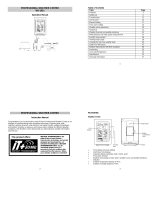
Carefully open and check that the following contents are complete:
Item: Consisting of: Fittings: Illustration:
Base
Station
1) Main unit

2
Thermo-
Hygro
Sensor
1) Main unit
2) Rain
protection
cover
1) Wall mounting
screws
2) Plastic
anchors for
screws
3) 2 x cable ties
Wind
Sensor
1) Main unit with
wind vane
2) 32ft cable
(already
attached the
main unit)
3) Mast holder
1) 1 x U-bolts for
mast holder
2) 2 x Washers
3) 2 x Nuts
4)
2 x cable ties
Rain
Sensor
1) Base and
funnel
2) 32ft cable
(already
attached the
main unit)
1) 2 x Screws
and Plastic
anchors

3
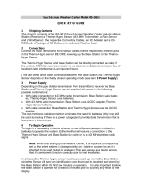
Setting Up:
Important: Operating power is supplied to both the wind and rain sensors by the
thermo-hygro sensor
Setting up using batteries:
1) Sensors: Pull and remove the protective rain cover of the Thermo-Hygro
Sensor to reveal 2 socket ports and the battery cover. Insert the cables of the
wind and rain sensors in the correctly marked sockets. Slide open the battery
Thermo-Hygro Sensor
Weather center
Battery compartment
Sockets for wind
and rain sensor

4
compartment and checking the correct polarity insert 2 x AA IEC, LR6 1.5V
batteries and replace the cover and rain cover
2) Base Station: Now open the battery cover at the back of the unit and checking
the correct polarity insert 3 x AA IEC, LR6 1.5V batteries and replace the battery
cover
Performing a function test and Setting time manually:
1. After powering up the units, the base station has to synchronize to the sensors
before the weather data can be received.
2. Afterwards, the Weather Station will start receiving data from the transmitter.
The outdoor temperature, humidity, windchill and wind speed should then be
displayed on the Weather Station. If this does not happen after 30 seconds, the
batteries will need to be removed from both units. You will have to start again
from the beginning.
3. You may then check all cables for correct connection and all components for
correct function by manually turning the wind-gauge, moving the weather-vane,
tilting the rain sensor to hear the impact of the internally moving seesaw, etc.
4. Time and date shall be manually set.
5. After the Weather Station has been checked for correct function with regard to
the above points and found fit, the initial set up of the weather station system is
finished and the mounting of the system components can take place. It must be
ensured however that all components work properly together at their chosen
mounting or standing locations. If e.g. there appear to be problems with the 915
MHz radio transmission, they can mostly be overcome by slightly changing the
mounting locations.

5
Note:
•
Should any outdoor data not be received from the sensors (when “- - -“ is
displayed), check all cables are correctly installed. Then user shall remove the
batteries from all units and redo the set-up procedures after about 5 minutes.
•
Wind speeds that read zero does not mean reception failure, it simply means
that there was no wind at the time of reading the data.
Mounting the units:
Users must take their surroundings into consideration before deciding which method
is best suited for them. Connection by cable is advantageous in that data from the
sensors to the base station is interference free. Using 915MHz wireless transmission
gives users little restriction on placement as that all units can be positioned virtually
anywhere to within a 330 ft radius of the base station. You must decide which method
is best suited to you. For cable connecting, please ensure that the cable included in
this set meets with your distance requirements (see accessories in the main user
manual for adding extension cables).
Important: Ensure all signals can be received and/or all cable distances meet with
your requirements at the point of fixing particularly before you start drilling any
mounting holes.
Wind sensor
Secure the main unit to the shaft of the mast holder using the single screw provided
with the front of the sensor (marked E) facing in the East-West direction otherwise

6
wind direction will not be accurate. Now fix the entire unit to a suitable mast using the
U-bolt, washers and nuts found in this set.
Note: For best results mount the wind sensor onto a mast to allow the wind to freely
travel from all directions to enable an accurate reading (ideal mast size should be
from Ø
5
/
8
” to 1
1
/
4
”). Ensure that the cable of the wind sensor meets your distance
requirements
Rain sensor
The rain sensor should be mounted horizontally about 2-3ft off from the ground in an
open area away from trees or other coverings to allow rain to fall naturally for an
accurate reading.
Note: For best results ensure the base is horizontal to allow maximum drainage of
any collected rain
Thermo-hygro Sensor
To wall mount the thermo-hygro sensor, fix the wall holder onto the desired wall (2
screws are supplied), plug the sensor firmly into the wall holder and then carefully
replace the rain cover back over the thermo-hygro sensor.
Note: After mounting the units, should the weather data not be received, user may
need to remove the batteries from all units and redo the set-up procedures after about
5 minutes.

7
WARRANTY
For warranty work, technical support, or information contact:
La Crosse Technology, Ltd
2809 Losey Blvd. South
La Crosse, WI 54601
Phone: 608.782.1610
Fax: 608.796.1020
Springfield / Lacrosse Canada.
1-800-661-6721
5151 Thimens Rd.
Montreal, Quebec
H4R 2C8
e-mail:
support@lacrossetechnology.com
(warranty work)
sales@lacrossetechnology.com
(information on other products)
web:
www.lacrossetechnology.com
For more information, please visit:
www.lacrossetechnology.com/1610itc
All rights reserved. This handbook must not be reproduced in any form, even in excerpts, or
duplicated or processed using electronic, mechanical or chemical procedures without written
permission of the publisher.

8
This handbook may contain mistakes and printing errors. The information in this handbook
is regularly checked and corrections made in the next issue. We accept no liability for
technical mistakes or printing errors, or their consequences.
All trademarks and patents are acknowledged.

15
Note: En cas de non-réception des données après que les appareils ont été mis en
place, retirer les piles de tous les appareils et recommencer la procédure de montage
après 5 minutes environ.
GARANTIE
Pour toute intervention sous garantie, support technique ou information, veuillez contacter
La Crosse Technology, Ltd
2809 Losey Blvd. South
La Crosse, WI 54601
Phone: 608.782.1610
Fax: 608.796.1020
Springfield / Lacrosse Canada.
1-800-661-6721
5151 Thimens Rd.
Montreal, Quebec
H4R 2C8
e-mail :
support@lacrossetechnology.com
(interventions sous garantie)
sales@lacrossetechnology.com
(informations sur les autres produits)
site web :
www.lacrossetechnology.com
Pour d'ample informations, visiter:
www.lacrossetechnology.com/1610itc

PROFESSIONAL WEATHER CENTER
WS-1610TWC-IT
Operation Manual

PROFESSIONAL WEATHER CENTER
WS-1610TWC-IT
Operation Manual

1
Table of Contents
Topic Page
Features 3
Setting up 6
Function keys 12
LCD Screen 14
Manual Setting 16
Time alarm setting 24
Weather alarm operations 25
Hysteresis 31
Weather forecast and weather tendency 32
Wind direction and wind speed measurement 36
Rainfall measurement 37
Viewing history data 37
Viewing the min/ max weather data 39
Switch On/ Off buzzer 46
Outdoor transmission 915 MHz reception 48
Positioning 49
Care and Maintenance 53
Specification 54
Warranty Info 56

2
PROFESSIONAL WEATHER CENTER
Instruction Manual
Congratulations on purchasing this state-of-the-art Professional Weather Center as an
example of excellent design and innovative technology. Featuring time, date,
calendar, weather forecast, wind direction and speed, rainfall, outdoor temperature
and outdoor humidity, air pressure and various alarm settings for different weather
conditions, this Weather Center will provide you with extensive weather information
and forecast.
INSTANT TRANSMISSION
is the
state-of-the-art new wireless
transmission technology, exclusively
designed and developed by LA
CROSSE TECHNOLOGY. INSTANT
TRANSMISSION
offers you an
immediate update (every 4 seconds!)
of all your outdoor data measured
from the transmitters: follow your
climatic variations in real-time!
This product offers:

3
FEATURES:
Weather Center
•
Time display (manual setting)
•
12/24 hour time display
•
Calendar display (weekday, date, month, year)
•
Time alarm function
•
Weather forecasting function with 3 weather icons and weather tendency
indicator
•
Outdoor temperature display in ºF/°C
•
Outdoor Humidity display as RH%
•
MIN/MAX value of outdoor temperature and humidity display with time & date
of recording
Function keys
LCD
Foldout stand I
Foldout stand II
Battery compartment
cover
Hanging hole

4
•
Low/High outdoor temperature and humidity alarm
•
Relative air pressure displayed in inHg or hPa
•
Air pressure tendency indicator for the past 12 hours (bargraph format)
•
LCD contrast selectable
•
Low battery indicator
•
Wind direction displayed in 16 steps
•
Wind speed displayed in mph, km/h, or m/s, and Beaufort scale
•
Wind chill displayed in °F of °C
•
Max wind speed displayed with time & date of recording
•
High alarm function for wind speed
•
Manual reset of outdoor temperature/ humidity, pressure and wind chill data
•
Total rainfall displayed in mm or inch
•
Storm warning alarm
•
Buzzer on/off selectable
•
Storage of 200 sets of history weather data recorded in 3-hour intervals
•
Wireless transmission at 915 MHz
•
Transmission range up to 330 feet (100 meters)
Thermo-hygro Sensor
•
Remote transmission of the outdoor temperature and humidity
to the Weather Center at 915 MHz
•
Weather-resistant casing
•
Wall mounting case (to be mounted in a sheltered place. Avoid
direct rain and sunshine)

5
Wind Sensor
•
Connected to the thermo-hygro sensor by cable
•
Can be installed onto a mast or a horizontal panel
Rain Sensor
•
Connected to the thermo-hygro sensor by cable
•
To be mounted onto a horizontal panel

6
SETTING UP:
Note:
When putting the Weather Center into operation, it is important to perform in close
proximity (e.g. on a table) a complete wiring and set-up of the system. This step is
Cable connection between
the wind sensor and the
thermo-hygro sensor
Cable connection between
the rain sensor and the
thermo-hygro sensor
W
ireless transmission at
915 MHz - thermo-
hygro
sensor
to the Weather
Center
Weather Center
Wind sensor
Rain sensor

7
important to test all components for correct function before placing and mounting
them at their final destinations (See Positioning below)
1. Unwind the cables of the Rain and the Wind sensors. Connect the Rain and
the Wind sensors to the Thermo-hygro sensor by plugging the connector heads
of the two sensors into the appropriate sockets of the Thermo-hygro sensor.
2. First insert the batteries into the Thermo-hygro sensor (see “How to install
and replace the batteries into the Thermo-hygro sensor“ below).
3. Then insert the batteries into the Weather Center (see “How to install and
replace the batteries into the Weather Center” below). Once the batteries
are installed, all segments of the LCD will light up briefly and a short signal
tone will be heard. It will then display the time as 12:00, the date as 1.1.05, the
weather icons, and air pressure value. "- - -" will be shown for outdoor data.
4. Afterwards, the Weather Center will start receiving data from the transmitter.
The outdoor temperature, humidity wind chill and wind speed should then be
Sockets for wind
and rain sensor

8
displayed on the Weather Center. If this does not happen after 30 seconds, the
batteries will need to be removed from both units. You will have to start again
from step 1.
5. You may then check all cables for correct connection and all components for
correct function by manually turning the wind-gauge, moving the weather-vane,
tilting the rain sensor to hear the impact of the internally moving seesaw, etc
(See Positioning below).
6. Time and date shall be manually set (See Manual Setting below).
7. After the Weather Center has been checked for correct function with regard to
the above points and found fit, the initial set up of the weather station system is
finished and the mounting of the system components can take place. It must be
ensured however that all components work properly together at their chosen
mounting or standing locations. If e.g. there appear to be problems with the
915 MHz radio transmission, they can mostly be overcome by slightly changing
the mounting locations.
Note:
The radio communication between the receiver and the transmitter in the open field
reaches distances of max 330 feet, provided there are no interfering obstacles such
as buildings, trees, vehicles, high voltage lines, etc.
8. Radio interferences created by PC screens, radios or TV sets can in some
cases entirely cut off radio communication. Please take this into consideration
when choosing standing or mounting locations.
/