Fujitsu AUXS018GLEH Installation guide
- Category
- Split-system air conditioners
- Type
- Installation guide
This manual is also suitable for

English
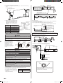
INSTALLATION MANUAL
INDOOR UNIT (3D fl ow cassette type)
For authorized service personnel only.
Deutsch
INSTALLATIONSANLEITUNG
INNENGERÄT (3D Fluss-Kassettentyp)
Nur für autorisiertes Fachpersonal.
AUXS018GLEH
AUXS024GLEH
TM
FrançaisEspañol
MANUEL D’INSTALLATION
MANUAL DE INSTALACIÓN
UNITÉ INTÉRIEURE (Type cassette à fl ux 3D)
UNIDAD INTERIOR (Tipo casete de fl ujo 3D)
Pour le personnel agréé uniquement.
Únicamente para personal de servicio autorizado.
Italiano
MANUALE DI INSTALLAZIONE
UNITÀ INTERNA (Tipo a cassetta con fl usso 3D)
A uso esclusivo del personale tecnico autorizzato.
ΕλληνικάPortuguês
ΕΓΧΕΙΡΙΔΙΟ ΕΓΚΑΤΑΣΤΑΣΗΣ
ΕΣΩΤΕΡΙΚΗ ΜΟΝΑΔΑ (τύπος κασέτας με ροή 3D)
Μόνο για εξουσιοδοτημένο τεχνικό προσωπικό.
MANUAL DE INSTALAÇÃO
UNIDADE INTERIOR (tipo de cassete de fl uxo 3D)
Apenas para técnicos autorizados.
РусскийTürkçe
РУКОВОДСТВО ПО УСТАНОВКЕ
ВНУТРЕННИЙ МОДУЛЬ (кассетный тип с 3D потоком)
Только для авторизованного обслуживающего персонала.
MONTAJ KILAVUZU
İÇ ÜNİTE (3D akış kaset tipi)
Yalnızca yetkili servis personeli için.
MADE IN P.R.C.
Refer to the rating label for the serial number,
manufactured year and month.
PART No. 9383489013
[Original instructions]
9383489013_IM.indb 19383489013_IM.indb 1 08-Feb-19 17:11:2008-Feb-19 17:11:20

En-1
1. SAFETY PRECAUTIONS
• Be sure to read this Manual thoroughly before installation.
• The warnings and precautions indicated in this Manual contain important information
pertaining to your safety. Be sure to observe them.
• Hand this Manual, together with the Operating Manual to the customer. Request the cus-
tomer to keep them on hand for future use, such as for relocating or repairing the unit.
WARNING
This mark indicates procedures which, if improperly per-
formed, might lead to the death or serious injury of the user.
Request your dealer or a professional installer to install the unit in accordance with this
Manual.
An improperly installed unit can cause serious accidents such as water leakage, electric
shock, or fire.
If the unit is installed in disregard of the instructions in the Installation Manual, it will void
the manufacturer’s warranty.
Do not turn ON the power until all work has been completed.
Turning ON the power before the work is completed can cause serious accidents such
as electric shock or fire.
If refrigerant leaks while work is being carried out, ventilate the area.
If the refrigerant comes in contact with a flame, it produces a toxic gas.
Installation work must be performed in accordance with national wiring standards by
authorized personnel only.
Except for EMERGENCY, never turn off main as well as sub breaker of the indoor units
during operation. It will cause compressor failure as well as water leakage. First, stop
the indoor unit by operating the control unit, converter or external input device and then
cut the breaker. Make sure to operate through the control unit, converter or external
input device. When the breaker is designed, locate it at a place where the users cannot
start and stop in the daily work.
CAUTION
This mark indicates procedures which, if improperly performed,
might possibly result in personal harm to the user, or damage
to property.
Read carefully all security information before use or install the air conditioner.
Do not attempt to install the air conditioner or a part of the air conditioner by yourself.
This unit must be installed by qualified personnel with a capacity certificate for handling
refrigerant fluids. Refer to regulation and laws in use on installation place.
The installation must be carried out in compliance with regulations in force in the place
of installation and the installation instructions of the manufacturer.
This unit is part of a set constituting an air conditioner. It must not be installed alone or
with non-authorized by the manufacturer.
Always use a separate power supply line protected by a circuit breaker operating on all
wires with a distance between contact of 3mm for this unit.
The unit must be correctly earthed (grounded) and the supply line must be equipped
with a differential breaker in order to protect the persons.
The units are not explosion proof and therefore should not be installed in explosive
atmosphere.
Never touch electrical components immediately after the power supply has been turned
off. Electric shock may occur. After turning off the power, always wait 5 minutes before
touching electrical components.
This unit contains no user-serviceable parts. Always consult authorized service person-
nel to repairs.
When moving, consult authorized service personnel for disconnection and installation
of the unit.
2. ABOUT THIS PRODUCT
2.1. Precautions for using the R410A refrigerant
WARNING
Do not introduce any substance other than the prescribed refrigerant into the refrigera-
tion cycle.
If air enters the refrigeration cycle, the pressure in the refrigeration cycle will become
abnormally high and cause the piping to rupture.
If there is a refrigerant leakage, make sure that it does not exceed the concentration
limit.
If a refrigerant leakage exceeds the concentration limit, it can lead to accidents such as
oxygen starvation.
Do not touch refrigerant that has leaked from the refrigerant pipe connections or other
area. Touching the refrigerant directly can cause frostbite.
If a refrigerant leakage occurs during operation, immediately vacate the premises and
thoroughly ventilate the area.
If the refrigerant comes in contact with a flame, it produces a toxic gas.
2.2. Special tool for R410A
WARNING
To install a unit that uses R410A refrigerant, use dedicated tools and piping materi-
als that have been manufactured specifically for R410A use. Because the pressure
of R410A refrigerant is approximately 1.6 times higher than the R22, failure to use
dedicated piping material or improper installation can cause rupture or injury.
Furthermore, it can cause serious accidents such as water leakage, electric shock, or
fire.
Tool name Contents of change for R22 tool
Gauge manifold
The pressure in the refrigerant system is extremely high and cannot
be measured with a conventional (R22) gauge. To prevent errone-
ous mixing of other refrigerants, the diameter of each port has been
changed. It is recommended to use a gauge manifold with a high
pressure display range of –0.1 to 5.3 MPa and a low pressure display
range of –0.1 to 3.8 MPa.
Charging hose
To increase pressure resistance, the hose material and base size
were changed.
(The charging port thread diameter for R410A is 1/2 UNF 20 threads
per inch.)
Vacuum pump
A conventional (R22) vacuum pump can be used by installing a
vacuum pump adapter.
Be sure that the pump oil does not backflow into the system. Use one
capable for vacuum suction of –100.7 kPa (5 Torr, –755 mmHg).
Gas leakage
detector
Special gas leakage detector for R410A refrigerant.
INSTALLATION MANUAL
PART No. 9383489013
VRF system indoor unit (3D flow cassette type)
Contents
1. SAFETY PRECAUTIONS ........................................................................................... 1
2. ABOUT THIS PRODUCT ............................................................................................ 1
2.1. Precautions for using the R410A refrigerant ........................................................ 1
2.2. Special tool for R410A ......................................................................................... 1
2.3. Accessories ......................................................................................................... 2
2.4. Optional parts ...................................................................................................... 2
3. INSTALLATION WORK .............................................................................................. 2
3.1. Selecting an installation location .......................................................................... 2
3.2. Installation dimensions ........................................................................................ 3
3.3. Installing the unit .................................................................................................. 3
4. PIPE INSTALLATION .................................................................................................. 4
4.1. Selecting the pipe material .................................................................................. 4
4.2. Pipe requirement ................................................................................................. 4
4.3. Flare connection (pipe connection) ...................................................................... 4
4.4. Installing heat insulation ...................................................................................... 5
5. INSTALLING DRAIN PIPES ....................................................................................... 5
6. ELECTRICAL WIRING ................................................................................................ 6
6.1. Electrical requirement .......................................................................................... 7
6.2. Wiring method ...................................................................................................... 7
6.3. Unit wiring ............................................................................................................ 7
6.4. Connection of wiring ............................................................................................ 8
6.5. Optional parts wiring ............................................................................................ 9
6.6. External input and external output (Optional parts) ............................................. 9
7. FIELD SETTING ........................................................................................................ 11
7.1. Setting the address ............................................................................................ 11
7.2. Custom code setting .......................................................................................... 11
7.3. Function setting ................................................................................................. 11
8. GRILLE INSTALLATION ........................................................................................... 12
9. TEST RUN ................................................................................................................. 12
9.1. Test run using Outdoor unit (PCB) ..................................................................... 12
9.2. Test run using remote controller ........................................................................ 12
10. CHECK LIST ............................................................................................................. 12
11. ERROR CODES ........................................................................................................ 13
9383489013_IM.indb 19383489013_IM.indb 1 08-Feb-19 17:11:2008-Feb-19 17:11:20

En-2
2.3. Accessories
WARNING
For installation purposes, be sure to use the parts supplied by the manufacturer or other
prescribed parts.
The use of non-prescribed parts can cause serious accidents such as the unit to fall,
water leakage, electric shock, or fire.
The following installation parts are furnished. Use them as required.
Keep the Installation Manual in a safe place and do not discard any other accessories
until the installation work has been completed.
Name and Shape Q’ty Application
Operation manual
1
Installation manual
1
(This book)
Operating Manual
(CD-ROM)
1
Cable tie (large)
4
For fixing the connection pipe
(large and small).
Cable tie (medium)
1
For transmission and remote
controller cable binding.
Push mount cable tie
1
For transmission and remote
controller cable binding.
Coupler heat insulation (small)
1
For indoor side pipe joint (small).
Coupler heat insulation (large)
1
For indoor side pipe joint (large).
Template
CAUTION
1
For installing indoor unit.
Washer
8
For installing indoor unit.
Insulation
1
For installing drain pipe
Drain hose
1
For installing drain pipe.
VP25 (O.D.32, I.D.25)
Hose band
1
For installing drain hose.
Hook wire
1
For installing indoor unit.
2.4. Optional parts
Description Model Application
External connect kit
UTY-XWZXZC
For output function.
(Output terminal / CNB01)
UTY-XWZXZB
For control input function.
(Apply voltage terminal / CNA01)
UTY-XWZXZD
For control input function.
(Dry contact terminal / CNA02)
UTY-XWZXZ7
For forced thermostat off function.
(Apply voltage terminal / CNA03)
UTY-XWZXZE
For forced thermostat off function.
(Dry contact terminal / CNA04)
IR receiver kit UTY-TRHX For air conditioner operation.
MODBUS® conver-
tor
UTY-VMSX For connecting to the Modbus network.
Wireless LAN
adapter
UTY-TFSXZ* For wireless LAN control.
External power sup-
ply unit
UTZ-GXXA
Supply power to the indoor unit PCB
when the indoor unit is turned off to
prevent errors.
3. INSTALLATION WORK
Correct initial installation location is important because it is difficult to move unit after it is
installed.
3.1. Selecting an installation location
Decide the mounting position together with the customer as follows.
WARNING
Select installation locations that can properly support the weight of the indoor. Install the
units securely so that they do not topple or fall.
CAUTION
Do not install the unit in the following areas:
• Area with high salt content, such as at the seaside.
It will deteriorate metal parts, causing the parts to fail or the unit to leak water.
• Area filled with mineral oil or containing a large amount of splashed oil or steam, such
as a kitchen.
It will deteriorate plastic parts, causing the parts to fail or the unit to leak water.
• Area that generates substances that adversely affect the equipment, such as sulfuric
gas, chlorine gas, acid, or alkali.
It will cause the copper pipes and brazed joints to corrode, which can cause refrigerant
leakage.
• Area that can cause combustible gas to leak, contains suspended carbon fibers or
flammable dust, or volatile inflammables such as paint thinner or gasoline.
If gas leaks and settles around the unit, it can cause a fire.
• Area where animals may urinate on the unit or ammonia may be generated.
Do not use the unit for special purposes, such as storing food, raising animals, growing
plants, or preserving precision devices or art objects.
It can degrade the quality of the preserved or stored objects.
Do not install where there is the danger of combustible gas leakage.
Do not install the unit near a source of heat, steam, or flammable gas.
Install the unit where drainage does not cause any trouble.
Install the indoor unit, power supply cable, transmission cable, and remote controller
cable at least 1 m away from a television or radio receivers. The purpose of this is to
prevent TV reception interference or radio noise.
(Even if they are installed more than 1 m apart, you could still receive noise under some
signal conditions.)
If children under 10 years old may approach the unit, take preventive measures so that
they cannot reach the unit.
Use the “Insulation kit for high humidity” (option), when the condition under the roof
is over 80% in humidity and over 30°C in temperature. Otherwise, there is a risk of
condensation on the ceiling.
Decide the mounting position with the customer as follows:
(1) Install the indoor unit on a place having a sufficient strength so that it withstands
against the weight of the indoor unit.
(2) The inlet and outlet ports should not be obstructed; the air should be able to blow all
over the room.
(3) Leave the space required to service the air conditioner.
(4) A place from where the air can be distributed evenly throughout the room by the unit.
(5) Install the unit where connection to the outdoor unit (or RB unit) is easy.
(6) Install the unit where the connection pipe can be easily installed.
(7) Install the unit where the drain pipe can be easily installed.
(8) Install the unit where noise and vibrations are not amplified.
(9) Take servicing, etc., into consideration and leave the spaces. Also install the unit
where the filter can be removed.
9383489013_IM.indb 29383489013_IM.indb 2 08-Feb-19 17:11:2008-Feb-19 17:11:20

En-3
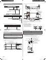
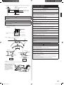
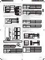
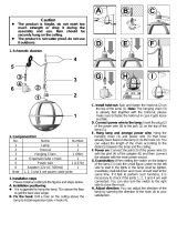
3.2. Installation dimensions
Ceiling height is as shown in the figure.
Side view
Strong and durable ceiling
2,100 to 3,200 mm
Floor
150 mm or more
260 mm
Front view
150 mm
or more
Distance between the indoor unit (bottom) and the ceiling board
50 mm
* Be sure to make the function settings with the remote controller according to the
installed ceiling height.
3.3. Installing the unit
WARNING
Install the air conditioner in a location which can withstand a load of at least 5 times the
weight of the indoor unit and which will not amplify sound or vibration. If the installation
location is not strong enough, the indoor unit may fall and cause injuries.
If the job is done with the panel frame only, there is a risk that the unit will come loose.
Please take care.
3.3.1. Position the ceiling hole and hanging bolts
(1) Positions of the ceiling opening, hanging bolt pitch, indoor unit frame and panel
frame.
• Ceiling opening and hanging bolt pitch. (unit: mm)
1,300 to 1,320
(Ceiling opening)
1,222 (Hanging bolt pitch)
460 (Hanging
bolt pitch)
580
(Panel frame)
530 to 550
(Ceiling opening)
500
(Body frame)
1,182 (Body frame)
58 (Control box)
1,350 (Panel frame)
• Refrigerant piping and drain piping positions. (unit: mm)
Gas pipe
Liquid pipe
Drain pipe
50
150
227
204
250
85
120
Drain pipe
(Connect the attached
drain hose)
435
105
65
(2) Hanging structure.
• Select a strong structure for the hanging location.
• If necessary, reinforce the hanging bolt with quakeproof columnar support material to
prevent shaking.
• Use hanging bolts of M8 to M10.
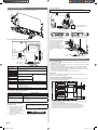
3.3.2. Hanging preparations
• Firmly fasten the hanging bolts as shown
in the figure or by another method.
• Install the hanging bolts at a place
where they would be capable of holding
a weight of at least 490 N per bolt.
Hole-in anchor
Hole-in plug
Concrete Insert
Hanging bolt M10
(locally purchased)
3.3.3. Body installation
WARNING
Perform final tightening by tightening the double nut firmly.
Be sure to install the indoor unit horizontally and adjust the height below the indoor unit
and the ceiling surface properly.
(1) Install the attached washer and nut (prepared on site) onto the hanging bolt.
(2) Hook the indoor unit onto the hanging bolt.
(3) Adjust the dimensions of the ceiling surface from the indoor unit.
After installing the grille, you can make fine adjustment of the height of the indoor
unit. For details, refer to the installation manual of the grille.
Hanging bolt (locally purchased)
Nut A (locally purchased)
Nut B (Double Nut)
(locally purchased)
30 mm or more
After installing the indoor
unit, tighten the nuts.
Washer (accessories)
Washer (accessories)
9383489013_IM.indb 39383489013_IM.indb 3 08-Feb-19 17:11:2108-Feb-19 17:11:21

En-4
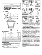
3.3.4. Leveling
• Base horizontal direction leveling on top of the indoor unit.
Ceiling
Level
• Give a slight tilt to the side to which the drain hose is connected. The tilt should be in the
range of 0 mm to 10 mm.
Drain hose
GOOD
PROHIBITED
10 mm or less
Level
Front
GOOD PROHIBITED
5 mm or less
4. PIPE INSTALLATION
CAUTION
Be more careful that foreign matter (oil, water, etc.) does not enter the piping than with
refrigerant R410A models. Also, when storing the piping, securely seal the openings by
pinching, taping, etc.
While welding the pipes, be sure to blow dry nitrogen gas through them.
4.1. Selecting the pipe material
CAUTION
Do not use existing pipes from another refrigeration system or refrigerant.
Use pipes that have clean external and internal sides without any contamination which
may cause trouble during use, such as sulfur, oxide, dust, cutting waste, oil, or water.
It is necessary to use seamless copper pipes.
Material : Phosphor deoxidized seamless copper pipes
It is desirable that the amount of residual oil is less than 40 mg/10 m.
Do not use copper pipes that have a collapsed, deformed, or discolored portion (es-
pecially on the interior surface). Otherwise, the expansion valve or capillary tube may
become blocked with contaminants.
Improper pipe selection will degrade performance. As an air conditioner using R410A
incurs pressure higher than when using conventional (R22) refrigerant, it is necessary to
choose adequate materials.
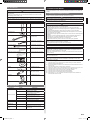
• Thicknesses of copper pipes used with R410A are as shown in the table.
• Never use copper pipes thinner than those indicated in the table even if they are avail-
able on the market.
Thicknesses of
Annealed Copper
Pipes (R410A)
Pipe outside diameter [mm (in)] Thickness [mm]
6.35 (1/4) 0.80
9.52 (3/8) 0.80
12.70 (1/2) 0.80
15.88 (5/8) 1.00
19.05 (3/4) 1.20
4.2. Pipe requirement
CAUTION
Refer to the installation manual for the outdoor unit for description of allowable pipe
length and height difference.
Use pipe with water-resistant heat insulation.
CAUTION
Install heat insulation around both the gas and liquid pipes. Failure to do so may cause
water leaks.
Use heat insulation with heat resistance above 120 °C. (Reverse cycle model only)
In addition, if the humidity level at the installation location of the refrigerant piping is
expected to exceed 70 %, install heat insulation around the refrigerant piping. If the
expected humidity level is 70 to 80 %, use heat insulation that is 15 mm or thicker and
if the expected humidity exceeds 80 %, use heat insulation that is 20 mm or thicker. If
heat insulation is used that is not as thick as specified, condensation may form on the
surface of the insulation. In addition, use heat insulation with heat conductivity of 0.045
W/(m·K) or less (at 20 °C).
4.3. Flare connection (pipe connection)
WARNING
Tighten the flare nuts with a torque wrench using the specified tightening method. Other-
wise, the flare nuts could break after a prolonged period, causing refrigerant to leak and
generate hazardous gas if the refrigerant comes into contact with a flame.
4.3.1. Flaring
Use special flare tool exclusive for R410A.
(1) Cut the connection pipe to
the necessary length with a
pipe cutter.
(2) Hold the pipe downward so
that cuttings will not enter the
pipe and remove any burrs.
(3) Insert the flare nut (always
use the flare nut attached to
the indoor and outdoor units
(or RB unit) respectively)
onto the pipe and perform
the flare processing with a
flare tool. Use the special
R410A flare tool. Leakage of
refrigerant may result if other
flare nuts are used.
(4) Protect the pipes by pinching
them or with tape to prevent
dust, dirt, or water from
entering the pipes.
Check if [L] is
flared uniformly
and is not cracked
or scratched.
Pipe
Die
Pipe outside
diameter
[mm (in)]
Dimension A
[mm]
(Flare tool for
R410A, clutch
type)
Dimension
B
0
-0.4
[mm]
6.35 (1/4)
0 to 0.5
9.1
9.52 (3/8) 13.2
12.70 (1/2) 16.6
15.88 (5/8) 19.7
19.05 (3/4) 24.0
When using conventional (R22)
flare tools to flare R410A pipes, the
dimension A should be approxi-
mately 0.5 mm more than indicated
in the table (for flaring with R410A
flare tools) to achieve the speci-
fied flaring. Use a thickness gauge
to measure the dimension A. It is
recommended that a R410A flaring
tool is used.
Pipe outside
diameter
[mm (in)]
Width across
flats of Flare nut
[mm]
6.35 (1/4) 17
9.52 (3/8) 22
12.70 (1/2) 26
15.88 (5/8) 29
19.05 (3/4) 36
Width across
flats
4.3.2. Bending pipes
• If pipes are shaped by hand, be careful not to collapse them.
• Do not bend the pipes in an angle more than 90°.
• When pipes are repeatedly bend or stretched, the material will harden, making it difficult
to bend or stretch them anymore.
• Do not bend or stretch the pipes more than 3 times.
CAUTION
To prevent breaking of the pipe, avoid sharp bends.
If the pipe is bent repeatedly at the same place, it will break.
4.3.3. Pipe connection
CAUTION
Be sure to install the pipe against the port on the indoor unit and the outdoor unit cor-
rectly. If the centering is improper, the flare nut cannot tightened smoothly. If the flare
nut is forced to turn, the threads will be damaged.
Do not remove the flare nut from the indoor unit pipe until immediately before connect-
ing the connection pipe.
Do not use mineral oil on flared part. Prevent mineral oil from getting into the system as
this would reduce the lifetime of the units.
Hold the torque wrench at its grip, keeping it at a right angle with the pipe, in order to
tighten the flare nut correctly.
9383489013_IM.indb 49383489013_IM.indb 4 08-Feb-19 17:11:2208-Feb-19 17:11:22

En-5
(1) Detach the caps and plugs from the pipes.
(2) Center the pipe against the port on the indoor unit, and then turn the flare nut by
hand.
Connection pipe (Gas)
Connection pipe (Liquid)
(3) When the flare nut is tightened properly
by your hand, hold the indoor unit side
coupling with a separate spanner, then
tighten with a torque wrench. (See the
table below for the flare nut tightening
torques.)
Tighten with 2
wrenches.
Holding
wrench
Flare nut
Connection pipe
Indoor unit pipe
(Body side)
Torque
wrench
Flare nut
[mm (in)]
Tightening torque
[N·m (kgf·cm)]
6.35 (1/4) dia. 16 to 18 (160 to 180)
9.52 (3/8) dia. 32 to 42 (320 to 420)
12.70 (1/2) dia. 49 to 61 (490 to 610)
15.88 (5/8) dia. 63 to 75 (630 to 750)
19.05 (3/4) dia. 90 to 110 (900 to 1,100)
4.4. Installing heat insulation
CAUTION
After checking for gas leaks (refer to the Installation Manual of the outdoor unit), perform
this section.
Install heat insulation around both the large (gas) and small (liquid) pipes. Failure to do
so may cause water leaks.
After checking for gas leaks,
insulate by wrapping insula-
tion around the 2 parts (gas
and liquid) of the indoor unit
coupling, using the Coupler
heat insulation.
After installing the Coupler
heat insulation, wrap both ends
with vinyl tape so that there is
no gap.
Cable tie (large)
(accessories)
Indoor
unit
Be sure to overlap
the insulation
Coupler heat
insulation
Coupler heat
insulation
(accessories)
No gap
CAUTION
Must fit tightly against indoor unit without any gap.
5. INSTALLING DRAIN PIPES
WARNING
Do not insert the drain piping into the sewer where sulfurous gas occurs. (Heat ex-
change erosion may occur)
Insulate the parts properly so that water will not drip from the connection parts.
Check for proper drainage after the construction by using the visible portion of transpar-
ent drain port and the drain piping final outlet on the indoor unit.
CAUTION
Do not apply adhesive agent on the drain port of the indoor unit. (Use the attached drain
hose and connect the drain piping)
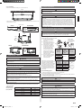
• Install the drain pipe with downward gradient (1/100 to 1/50) and so there are no rises or
traps in the pipe. Unsmooth draining caused by accumulated water flow in the pipe may
cause clogged drain.
• Use general hard polyvinyl chloride pipe (VP25) [outside diameter 32 mm].
• When the pipe is long, install supporters.
• Do not perform air bleeding. Drainage may
be blown out.
• If it is impossible to have sufficient gradient
of pipe, perform drain lift-up.
Pipe size
Drain pipe VP25 (O.D. 32 mm)
Hanging fittings
1.5 to 2 m
VP25 (O.D. 32 mm)
Downward gradient 1/100 to 1/50
Rise
PROHIBITED:
Trap
Air bleeding
When lifting up drain:
• Height of inclined pipe should be less than 850 mm from the ceiling. A rise dimension
over this range will cause leakage.
• Lift up the pipe vertically at the position of 300 mm or less from the unit.
300 mm or less
VP25 (O.D. 32 mm) local
arrangement
850 mm or less
650 mm
or less
Horizontal or upward
gradient (*1)
Downward gradient 1/100 to 1/50
*1: Install the drain hose horizontally or with a slight upward gradient so air pocket is not
generated in the drain pipe. The air pocket may cause noise occurred due to water
backfl ow when the drain pump is stopped.
VP30 (O.D. 38 mm) or more Downward gradient
1/100 to 1/50
850 mm or less
Working procedure
(1) Be sure to use supplied Drain hose ① and Hose band ②.
② Hose band (accessories)
Drain hole
① Drain hose (accessories)
Hard PVC side
Hose band
4 mm or less
20 mm
② Hose band
① Drain hose
Fasten the Hose band ② at the position where horizon-
tal against earth (ground).
The Hose band ② must be positioned at the right side
of the Drain hose ① as in the figure.
9383489013_IM.indb 59383489013_IM.indb 5 08-Feb-19 17:11:2308-Feb-19 17:11:23

En-6
(2) Be sure to connect Drain pipe with adhesive (polyvinyl chloride) so that there is no
leakage.
Applying
area of
adhesive
Joint pipe (locally purchased)
Drain pipe (VP25)
(locally purchased)
4 mm or less
CAUTION
Do not connect to the Drain hole with adhesive. Using adhesive may cause damage
and water leaks.
(3) After installing the Drain hose ①, check if the drainage is smooth.
CAUTION
To prevent excessive force on Drain hose ①, avoid bends or twists. (To bend or twist
may cause water leaks.)
(4) After checking for drainage, attach the Drain hose insulation ③ to insulate, following
the instructions as in the figures.
To avoid space with Drain hose ① and Hose band ②, press firmly the Drain hose
insulation ③.
③ Insulation
(accessories)
Ensure there is no
space.
• STEP1 - STEP3
Butt the insulation against the unit.
STEP 1
Unit
Slit
Press firmly
Press firmly
STEP 2
Slit
Press firmly
Roll the insulation over the joint.
Press firmly
STEP 3
Press firmly
Slit
• FINISH
Check that there is no gap between the unit and the drain hose insulation.
NOTE: Check for drainage
Pour about 1 liter of water
from the position shown in the
diagram or from the airflow
outlet to the drain pan.
Check for any abnormalities
such as strange noises and
whether the drain pump func-
tions normally.
6. ELECTRICAL WIRING
WARNING
Electrical work must be performed in accordance with this Manual by a person certified
under the national or regional regulations. Be sure to use a dedicated circuit for the unit.
An insufficient power supply circuit or improperly performed electrical work can cause
serious accidents such as electric shock or fire.
Before starting work, check that power is not being supplied to the all units.
For wiring, use the prescribed type of cables, connect them securely, making sure that
there are no external forces of the cables applied to the terminal connections.
Improperly connected or secured cables can cause serious accidents such as overheat-
ing the terminals, electric shock, or fire.
Securely install the electrical box cover on the unit.
An improperly installed electrical box cover can cause serious accidents such as electric
shock or fire through exposure to dust or water.
Install sleeves into any holes made in the walls for wiring. Otherwise, a short circuit
could result.
Use the included connection cables and power cables or ones specified by the manu-
facturer. Improper connections, insufficient insulation, or exceeding the allowable current
can cause electric shock or fire.
Do not modify the power cables, use extension cables, or use any branches in the wir-
ing. Improper connections, insufficient insulation, or exceeding the allowable current can
cause electric shock or fire.
Match the terminal block numbers and connection cable colors with those of the outdoor
unit (or RB unit). Erroneous wiring may cause burning of the electric parts.
Securely connect the connection cables to the terminal board. In addition, secure the
cables with wiring holders. Improper connections, either in the wiring or at the ends of
the wiring, can cause a malfunction, electric shock, or fire.
Always fasten the outside covering of the connection cable with the cable clamp. (If the
insulator is chafed, electric discharge may occur.)
Install an earth leakage breaker. In addition, install the earth leakage breaker so that the
entire AC main power supply is cut off at the same time. Otherwise, electric shock or fire
could result.
Always connect the earth (ground) cable.
Improper earthing (grounding) work can cause electric shocks.
Install the remote controller cables so as not to be direct touched with your hand.
Perform wiring work in accordance with standards so that the air conditioner can be
operated safely and positively.
Connect the connection cable firmly to the terminal board. Imperfect installation may
cause a fire.
If the supply cable is damaged, it must be replaced by the manufacturer, its service
agent or similarly qualified persons in order to avoid a hazard.
CAUTION
Earth (Ground) the unit.
Do not connect the earth (ground) cable to a gas pipe, water pipe, lightning rod, or a
telephone earth (ground) cable.
Improper earthing (grounding) may cause electric shock.
Do not connect power supply cables to the transmission or remote controller terminals,
as this will damage the product.
Never bundle the power supply cable and transmission cable, remote control cable
together. Separate these cable by 50 mm or more. Bundling these cables together will
cause miss operation or breakdown.
When handling PCB, static electricity charged in the indoor unit may cause malfunction
of the PCB. Follow the cautions below:
• Establish an earth (ground) for the indoor and outdoor units and peripheral devices.
• Cut power (breaker) off.
• Touch metal part of the indoor units for more than 10 seconds to discharge static
electricity charged in the indoor unit.
• Do not touch terminals of parts and patterns implemented on PCB.
9383489013_IM.indb 69383489013_IM.indb 6 08-Feb-19 17:11:2408-Feb-19 17:11:24

En-7
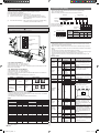
6.1. Electrical requirement
• Select the power cable type and size
in accordance with relevant local and
national regulations.
• Specifications for local wiring power cord
and branch wiring are in compliance with
local code
Voltage rating
230 V
Operating
range
198 to 264 V (50 Hz)
198 to 253 V (60 Hz)
• Max. wire length: Set a length so that the voltage drop is less than 2%. Increase the wire
diameter when the wire length is long.
Breaker should be installed at every refrigerant system. Do not use a breaker in a different
refrigerant system.
Refer to the table for the breaker specifications of each installation condition. Perform
the power crossover wiring within the range of the same refrigerant system. When the
crossover wiring is done, make a connection for indoor units to satisfy conditions A and B
below.
A. Current breaker requirements
Model MCA MFA
MCA:
Minimum Circuit Ampacity
MFA:
Maximum Fuse Ampacity
AUXS018GLEH 0.44 A
20 A
AUXS024GLEH 0.65 A
When the power crossover wiring is done, make it so that the total of the MCA of the con-
nected RB units and indoor units does not exceed the 15 A. For RB unit MCA, refer to the
RB unit installation manual.
If the capacity of connected RB units and indoor units exceeds the upper limit, either add
breakers or use a breaker with a greater capacity.
B. Earth leakage breaker requirements
• 2 indoor units (including RB unit) = 1 indoor unit of the 3D flow cassette type
Breaker capacity
Maximum connect-
able “indoor units”
or “indoor units +
RB units” (*1)
*1: Heat pump type: indoor units,
Heat recovery type: indoor units
and RB units.
*2: If the 100 mA capacity breaker is
not provided, split the quantity of
the indoor units into small groups
of 9 units or less and provide a
breaker with capacity of 30 mA for
each group.
30 mA, 0.1 sec or less 44 or less
100 mA, 0.1 sec or less 45 to 148 (*2)
6.1.1. Cable specifi cations
Recommended
cable size (mm
2
)
Cable type Remark
Power supply
cable
2.5
Type245 IEC57 or
equivalent
2 Cable + earth (ground)
Transmission cable 0.33
LONWORKS compat-
ible cable
22 AWG
LEVEL 4 (NEMA) non-
polar 2 core, twisted pair
solid core diameter 0.65 mm
Remote controller
cable
(2-wire type)
0.33 to 1.25 Shield cable
Non-polar 2 core,
twisted pair
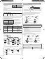
6.2. Wiring method
Example
*2 *2
*2
*3 *3 *3
Outdoor unit or RB unit *1
Transmission
Transmission
Indoor unit
Remote controller
(Master)
Power supply
Indoor unit Indoor unit
Power supply
Remote
control
Breaker
Breaker
Breaker
Remote controller
(Slave)
Remote controller
*1: When connecting to the Heat Recovery System, refer to the installation manual of the
RB unit.
*2: Earth (Ground) the remote controller if it has an earth (ground) cable.
*3: The 3-wire type remote controller is not used.
(Crossover wiring of power supply)
Indoor unit
Pull box
Pull box
Power supply Power supply Power supply
Indoor unit Indoor unit
Breaker
Power supply
6.3. Unit wiring
• Before attaching the cable to terminal block.
6.3.1. Power supply cable
Earth (Ground) cable
20 mm
30 mm
A. For solid core wiring
(1) To connect the electrical terminal, follow the below diagram and connect after looping
it around the end of the cable.
(2) Use the specified cables, connect them securely, and fasten them so that there is no
stress placed on the terminals.
(3) Use an appropriate screwdriver to tighten the terminal screws.
Do not use a screwdriver that is too small, otherwise, the screw heads may be dam-
aged and prevent the screws from being properly tightened.
(4) Do not tighten the terminal screws too much, otherwise, the screws may break.
(5) See the table for the terminal screw tightening torques.
(6) Please do not fix 2 power supply cables with 1 screw.
Strip 25 mm
Screw with
special washer
Screw with
special washer
Cable end (Loop)
Loop
Terminal block
Cable end (Loop)
Cable
Cable
Do not apply branch wiring. It may result electric shock or fire.
WARNING
When using solid core cables, do not use the ring terminal. If you use the solid core
cables with the ring terminal, the ring terminal's pressure bonding may malfunction and
cause the cables to abnormally heat up.
B. For strand wiring
(1) Use ring terminals with insulating sleeves as shown in the figure below to connect to
the terminal block.
(2) Securely clamp the ring terminals to the cables using an appropriate tool so that the
cables do not come loose.
(3) Use the specified cables, connect them securely, and fasten them so that there is no
stress placed on the terminals.
(4) Use an appropriate screwdriver to tighten the terminal screws. Do not use a screw-
driver that is too small, otherwise, the screw heads may be damaged and prevent the
screws from being properly tightened.
(5) Do not tighten the terminal screws too much, otherwise, the screws may break.
(6) See the table for the terminal screw tightening torques.
(7) Please do not fix 2 power supply cables with 1 screw.
Strip 10 mm
Ring terminal
Sleeve
Screw with
special washer
Screw with
special washer
Ring terminal
Terminal block
Ring terminal
Cable
Cable
WARNING
Use ring terminals and tighten the terminal screws to the specified torques, otherwise,
abnormal overheating may be produced and possibly cause heavy damage inside the
unit.
Terminal number Tightening torque
M3.5 screw
(Power supply/L, N, GND)
1.2 to 1.8 N·m
(12 to 18 kgf·cm)
9383489013_IM.indb 79383489013_IM.indb 7 08-Feb-19 17:11:2408-Feb-19 17:11:24

En-8
6.3.2. Transmission and Remote controller cable
Transmission cable Remote controller cable
Shield cable
(no film)
30 mm
45 mm
30 mm
• Connect remote controller and transmission cables as shown in following figure.
GOOD
PROHIBITED
Different diameter
Connect to 1 side
WARNING
Tighten the terminal screws to the specified torques, otherwise, abnormal overheating
may be produced and possibly cause heavy damage inside the unit.
Tightening torque
M3 screw (Transmission / X1, X2)
(Remote controller / Y1, Y2)
0.5 to 0.6 N·m
(5 to 6 kgf·cm)
CAUTION
To peel the film from the lead cable, use a dedicated tool that will not damage the
conductor cable.
When installing a screw on the terminal block, do not cut the cable by overtightening the
screw. On the other hand, an undertightened screw can cause faulty contact, which will
lead to a communication failure.
6.4. Connection of wiring
(1) Use a screw driver to loosen one screw at the bottom of the Indoor unit and remove
the cover.
(2) Disconnect the connector from the switch circuit board. Then, loosen one screw and
remove the sheet metal.
Connector
(3) After wiring is complete, secure the cables with the cable clamps.
Cable clamp
Earth (ground)
Power supply cable
(4) Connect the transmission and remote controller cables by passing the cables through
the hole shown in the diagram below. Once all cables are connected, tie the power
cable using a push mount cable tie, and tie the transmission and remote controller
cables using a cable tie.
Cable tie (medium)
(accessories)
Push mount
cable tie
(accessories)
Y1, Y2: Remote controller cable
X1, X2: Transmission cable
(5) Attach the hook wire. As show below, loosen the screw at the specified location and
attach the hook wire.
Hook wire
(accessories)
(6) Once all cables are connected, replace the cover and fix it with the screws. Cure the
wiring connecting port and remote controller connecting port with putty or heat insula-
tion so that insects or dust will not enter the unit.
CAUTION
Do not bundle the remote controller cable, or wire the remote controller cable in parallel,
with the indoor unit connection wire (to the outdoor unit) and the power supply cable. It
may cause erroneous operation.
9383489013_IM.indb 89383489013_IM.indb 8 08-Feb-19 17:11:2508-Feb-19 17:11:25

En-9
6.5. Optional parts wiring
Pull down the circuit board while pressing the hook as shown below.
6.5.1. Layout of the indoor unit PCB
Power indicator
lamp (green)
DIP switch
Name Application
Power indicator
lamp (green)
Indicates the state of the power supply. Refer to “Power indicator
lamp status” following.
CN150 Connect to the Grille. (*1)
CN151
CN152
CNA01 Apply voltage terminal For external input
CNA03
CNA02 Dry contact terminal
CNA04
DIP switch SET 2
(SW2)
Input signal type switching
CNB01 Output terminal For external outnput
CN48 For IR receiver unit (*1)
CN65 For one of the following.
• MODBUS® convertor (*1)
• Wireless LAN adapter (*1)
CN820 For External power supply unit (*1)
*1: For details, refer to each installation manual.
6.5.2. Power indicator lamp status
Power indicator lamp (Green) Status contents
Lit
Lit when the power is turned on.
Fast flashing (every 0.1
second)
There is a fault with the communication board or the
main board.
Blinking (repeat 3 seconds ON
and 1 second OFF)
The indoor unit is turned off and power is supplied
from the External power supply unit (optional) to the
indoor unit PCB.
6.5.3. Connection methods
Wire modification for External
input/output wire
(1) Remove insulation from wire at-
tached to wire kit connector.
(2) Remove insulation from field
supplied cable. Use crimp type
insulated butt connector to join field
cable and wire kit wire.
(3) Connect the wire with connecting
wire with solder.
IMPORTANT:
Be sure to insulate the connection between the
wires.
Locally
purchased
Solder and insulate the connected parts.
Wire kit connector
(optional parts)
Wiring arrangement
In following figure, all the possible connectors are connected for description.
In actual installation, you cannot connect all the connectors at once.
EMI core (accessory of
the IR receiver unit)
Cable of the External power supply unit
Cable of the IR receiver unit
Cable clampCable clamp
Once all connectors required for
connection are connected, push
up the circuit board that was
pulled down, and endure that
the hooks are in place.
Fix the connected cables by
passing them through the hole
using the grille accessory, cable
tie, as shown in the following
figure.
Cable tie (accessory of the grille)
6.6. External input and external output (Optional parts)
6.6.1. External input
• Indoor unit can be Operation/Stop, Emergency stop or Forced stop by using indoor unit
PCB CNA01 or CNA02.
• “Operation/Stop” mode, “Emergency stop” mode or “Forced stop” mode can be selected
with function setting of indoor unit.
• Indoor unit can be Forced thermostat off by using indoor unit PCB CNA03 or CNA04.
• A twisted pair cable (22 AWG) should be used. Maximum length of cable is 150 m.
• Use an external input and output cable with appropriate external dimension, depending
on the number of cables to be installed.
• The wire connection should be separate from the power cable line.
Input select
Use either one of these types of terminal according to the application. (Both types of
terminals cannot be used simultaneously.)
● Apply voltage terminal ([CNA01], [CNA03])
When a power supply must be provided at the input device you want to connect, use the
Apply voltage terminal ([CNA01], [CNA03]).
*a
*b
*1
CNA01
CNA03
*a
*a
Input
device 1
Input
device 2
Input
device 3
Load
resistance
Load
resistance
Load
resistance
DC power supply
12 to 24V
Connected unit
P.C.B
*1: Make the power supply DC12 to 24V. Select a power supply capacity with an ample
surplus for the connected load.
Do not impress a voltage exceeding 24V across pins 1-2, and 1-3.
*a: The allowable current is DC 5mA to 10mA. (Recommended: DC5mA)
Provide a load resistance such that the current becomes DC10mA or less.
Select very low current use contacts (usable at DC12V, DC1mA or less).
*b: The polarity is [+] for pin 1 and [-] for pin 2 and 3. Connect correctly.
9383489013_IM.indb 99383489013_IM.indb 9 08-Feb-19 17:11:2608-Feb-19 17:11:26

En-10
When connected to Apply voltage terminals of multiple indoor units with a connected unit,
be sure to make a branch outside the indoor unit using a pull box, etc. as shown on below
example.
CNA01
CNA01
CNA01
DC power supply
12 to 24V
Connected unit
Load
resistance
P.C.B
P.C.B
P.C.B
Input
device 1
Input
device 2
Indoor unit
Indoor unit
Indoor unit
Load
resistance
● Dry contact terminal ([CNA02], [CNA04])
When a power supply is unnecessary at the input device you want to connect, use the Dry
contact terminal ([CNA02], [CNA04]).
CNA02
*c
*c
*c
*d
CNA04
P.C.B
GND
Ch 1
Ch 3
Ch 2
Connected unit
*c: Select very low current use contacts (usable at DC12V, DC1mA or less).
*d: The wiring is different from Apply voltage terminals. Be sufficiently careful when wir-
ing.
When connected to Dry contact terminals of multiple indoor units with a connected unit,
insulate each indoor unit with relay, etc. as shown on below example.
K1
CNA02
CNA02
CNA02
K2
K3
K4
K5
K6
Power supply for relay
Indoor unit
Indoor unit
Indoor unit
Input device 2
Input device 1
K1 - K6: Relay
(Device for DC Current)
P.C.B
P.C.B
P.C.B
NOTE :
When connected to multiple indoor units directly, it will cause breakdown.
Operation behavior
● Input signal type
The input signal type can be selected.
It is switched by DIP switch on the indoor unit PCB.
Pulse
Edge
The width of pulse must be
longer than 200 msec.
DIP switch [Set 2 SW2] Input signal type
OFF (Factory setting) Edge
ON Pulse
● When function setting is “Operation/Stop” mode.
Input signal
type
Connector Input signal Command
Edge
Ch1 of CNA01
or CNA02
OFF → ON Operation
ON → OFF Stop
Pulse
CNA01 or
CNA02
Ch1
OFF → ON
Operation
Ch2
OFF → ON
Stop
* The last command has priority.
* The indoor units within the same remote controller group operates in the same mode.
● When function setting is “Emergency stop” mode.
Input signal
type
Connector Input signal Command
Edge
Ch1 of CNA01
or CNA02
OFF → ON Emergency stop
ON → OFF Normal
Pulse
CNA01 or
CNA02
Ch1
OFF → ON
Emergency stop
Ch2
OFF → ON
Normal
* All indoor units of same refrigerant system stops when Emergency stop operates.
● When function setting is “Forced stop” mode.
Input signal
type
Connector Input signal Command
Edge
Ch1 of CNA01
or CNA02
OFF → ON Forced stop
ON → OFF Normal
Pulse
CNA01 or
CNA02
Ch1
OFF → ON
Forced stop
Ch2
OFF → ON
Normal
* When the forced stop is triggered, indoor unit stops and Operation/Stop operation by a
remote controller is restricted.
* When forced stop function is used with forming a remote controller group, connect the
same equipment to each indoor unit within the group.
• Selection method of functions
“Operation/Stop” mode or “Emergency stop” mode, “Forced stop” mode can be selected
with function setting of indoor unit.
● Forced thermostat off function
[“Edge” input only]
Function
setting
Connector Input signal Command
60-00
Ch3 of CNA03 or
CNA04
OFF → ON Thermostat off
ON → OFF Normal
● Refrigerant leak detection function (only for J-IIIL series)
[“Edge” input only]
Function
setting
Connector Input signal Command
60-09
Ch3 of CNA03 or
CNA04
OFF → ON No command
ON → OFF Refrigerant leak
6.6.2. External output
• A twisted pair cable (22AWG) should be used. Maximum length of cable is 25m.
• Use an external input and output cable with appropriate external dimension, depending
on the number of cables to be installed.
• Output voltage: Hi DC12V±2V, Lo 0V.
• Permissible current: 50mA
Output select
● When indicator etc. are connected directly
Operation
indicator
Error
indicator
Indoor unit Fan
status indicator
connected unit
P.C.B
CNB
01
● When connecting with unit equipped with a power supply
CNB
01
P.C.B
Connected
device 1
Connected
device 2
Connected
device 3
connected unit Relay (locally purchased)
Operation behavior
Connector Output voltage Status
CNB01
External output 1
Pins 1-2
0V Stop
DC 12 V Operation
External output 2
Pins 1-3
0V Normal
DC 12 V Error
External output 3
Pins 1-4
0V Indoor unit fan stop
DC 12 V Indoor unit fan operation
9383489013_IM.indb 109383489013_IM.indb 10 08-Feb-19 17:11:2608-Feb-19 17:11:26

En-11
7. FIELD SETTING
There are 3 methods for address setting by FIELD SETTING as follows.
Please set by either of the methods.
Each setting method is described in below (1) to (3).
(1) IU AD, REF AD SW settings: This section (7.1. Setting the address)
(2) Remote controller settings: Refer to the wired or wireless remote controller
manual for detailed setting information. (Set IU AD,
REF AD SW to 0)
(3) Automatic address settings: Refer to the outdoor unit manual for detailed setting
information. (Set IU AD, REF AD SW to 0)
7.1. Setting the address
CAUTION
Use an insulated screwdriver to set the dip switches.
The rotary switches and slide switches to configure are located at the location shown
below.
SET3
×10 IU AD ×1 ×10 REF AD ×1
SET4
For refrigerant circuit
address
For indoor unit
address
7.1.1. Indoor unit address
• Rotary switch (IU AD × 1)...Factory setting “0”
• Rotary switch (IU AD × 10)...Factory setting “0”
When connecting multiple indoor units to 1 refrigerant system, set the address at IU AD
SW as shown in the Table A.
7.1.2. Refrigerant circuit address
• Rotary switch (IU AD × 1)...Factory setting “0”
• Rotary switch (IU AD × 10)...Factory setting “0”
In the case of multiple refrigerant systems, set REF AD SW as shown in the Table A for
each refrigerant system.
Set to the same refrigerant circuit address as the outdoor unit.
Setting
Setting range
Type of switch
Indoor unit ad-
dress
0 to 63
Setting ex-
ample
2
IU AD × 10 IU AD × 1
Refrigerant
circuit address
0 to 99
Setting ex-
ample
63
REF AD × 10 REF AD × 1
• If working in an environment where the wireless remote controller can be used, the ad-
dresses can also be set using the remote controller.
• If setting the addresses using the wireless remote controller, set the indoor unit address
and refrigerant circuit address to “00”.
(For information on setting using the wireless remote controller.)
Table A
Address
Rotary Switch Setting
Address
Rotary Switch Setting
Refrigerant circuit
REF AD SW
Indoor unit
IU AD SW
×
10
×
1
×
10
×
1
000000
101101
202202
303303
404404
505505
606606
707707
808808
909909
10 1 0 10 1 0
11 1 1 11 1 1
12 1 2 12 1 2
⁞⁞⁞⁞⁞⁞
99 9 9 63 6 3
Do not set the indoor unit address (IU AD SW) at 64 to 99.
It may result in failure.
7.2. Custom code setting
• Selecting the custom code prevents the indoor unit mix-up. (figure below)
(Up to 4 codes can be set.)
• Perform the setting for both the indoor unit and the remote controller.
Code change
Indoor unit
Remote
controller
Confusion
A B C D
A B C D
Custom code setting for indoor unit
Set the DIP switch SET3 SW1, 2, referring to
the figure and table below.
SET3
×10 IU AD ×1 ×10 REF AD ×1
SET4
DIP switch
“SET3”
SW
1
SW
2
SW
3
SW
4
ON
OFF
DIP switch “SET3”
DIP switch
SET3
Custom code
A (Factory
setting)
BCD
SW1 OFF ON OFF ON
SW2 OFF OFF ON ON
7.3. Function setting
• FUNCTION SETTING can be performed with the wired or wireless remote controller.
(The remote controller is optional equipment)
• Refer to the wired or wireless remote controller manual for detailed setting information.
• Refer to “7.1. Setting the address” for indoor unit address and refrigerant circuit address
settings.
• Turn the power of the indoor unit ON before starting the setting.
* Turning on the power to the indoor units initializes EEV, so make sure the piping air tight
test and vacuuming have been conducted before turning on the power.
* Also check again to make sure no wiring mistakes were made before turning on the
power.
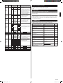
Function details
Function
Function
number
Setting number Default Details
Filter
indicator
interval
11
00 Standard
Adjust the filter cleaning interval
notification. If the notification is too
early, change to setting 01. If the
notification is too late, change to
setting 02.
01 Longer
02 Shorter
Filter
indicator
action
13
00 Enable
Enable or disable the filter indica-
tor. Setting 02 is for use with a
central remote controller.
01 Disable
02
Display only
on central
remote
controller
Ceiling
airflow
20
00 Standard
Regulate the airflow accordingto
the needs of the installationloca-
tion. When set to 01, the airflow
will be stronger.
01
High
Ceiling
(Forbidden)
23
(Forbidden)
24
Installation
position
setting
27
00 Center
Setting to switch the airflow
direction based on the installation
position of the indoor unit.
Center RightLeft
01 Right
02 Left
Cool air
tem-
perature
trigger
30
00 Standard
Adjust the cool air trigger
temperature. To lower the trigger
temperature, use setting 01. To
raise the trigger temperature, use
setting 02.
01 Adjust (1)
02 Adjust (2)
Heat air
tempera-
ture trigger
31
00 Standard
Adjust the heat air trigger tempera-
ture. To lower the trigger tempera-
ture by 6 degrees C, use setting
01. To lower the trigger temperature
by 4 degrees C, use setting 02. To
raise the trigger temperature, use
setting 03.
01 Adjust (1)
02 Adjust (2)
03 Adjust (3)
Auto restart 40
00 Enable
Enable or disable automatic system
restart after a power outage.
01 Disable
Cool Air
Prevention
43
00 Super low
Restrain the cold airflow with mak-
ing the airflow lower when starting
heating operation. To correspond to
the ventilation, set to 01.
01
Follow the
setting on
the remote
controller
9383489013_IM.indb 119383489013_IM.indb 11 08-Feb-19 17:11:2608-Feb-19 17:11:26

En-12
Function
Function
number
Setting number Default Details
External
control
46
00 Start/Stop
Allow an external controller to start
or stop the system, or to perform an
emergency stop.
If an emergency stop is performed
from an external controller, all
refrigerant systems will be disabled.
If forced stop is set, indoor unit
stops by the input to the external
input terminals, and Start/Stop by a
remote controller is restricted.
01
Emergency
stop
02 Forced stop
Error report
target
47
00 All
Change the target for reporting er-
rors. Errors can either be reported
in all locations, or only on the
central remote controller.
01
Display only
on central
remote
controller
Fan setting
when
cooling
thermostat
OFF
49
00
Follow the
setting on
the remote
controller
When set to 01, the fan stops when
the thermostat is OFF in cooling
operation. Connection of the wired
remote controller (2-wire type
or 3-wire type) and switching its
thermistor are necessary.
01 Stop
Switching
function for
external
inputs
60
00
Forced ther-
mostat off
Setting is required when connecting
a refrigerant-leak detecting device.
(only for J-IIIL series)
01
(Forbidden)
02
03
04
05
06
07
08
09
Refrigerant
leak detection
(Forbidden) 61 00
(Forbidden) 62 00
Auto mode
type
68
00
Single
setpoint
auto mode
(traditional)
Switch the setting method of auto
mode to single or dual (cooling/
heating).
For heat pump systems, it is neces-
sary to set the master indoor unit
(by wired remote controller).
01
Dual setpoint
auto mode
Deadband
value
69
00 0°C
Choose the minimum temperature
between cooling and heating set-
tings (deadband) for Dual
setpoint auto mode (set in No. 68).
01 0.5°C
02 1.0°C
03 1.5°C
04 2.0°C
05 2.5°C
06 3.0°C
07 3.5°C
08 4.0°C
09 4.5°C
(Forbidden) 71 00
(Forbidden) 72 00
(Forbidden) 73 00
(Forbidden) 74 00
(Forbidden) 75 00
8. GRILLE INSTALLATION
• Operate according to the installation manual of the grille.
• Be sure to confirm there is no gap between the grille and indoor unit after installing the
grille.
9. TEST RUN
9.1. Test run using Outdoor unit (PCB)
Refer to the Installation Manual for the outdoor unit if the PCB for the outdoor unit is to be
used for the test run.
9.2. Test run using remote controller
• Refer to the Installation Manual for the remote controller to perform the test run using the
remote controller.
• When the air conditioner is being test run, the OPERATION and TIMER indicator lamp
flash slowly at the same time.
10. CHECK LIST
Pay special attention to the check items below when installing the indoor unit(s). After
installation is complete, be sure to check the following check items again.
Check items If not performed correctly Check box
Has the indoor unit been installed
correctly?
Vibration, noise, indoor unit may
drop
Has there been a check for gas leaks
(refrigerant pipes)?
No cooling, No heating
Has heat insulation work been com-
pleted?
Water leakage
Does water drain easily from the indoor
units?
Water leakage
Is the voltage of the power source the
same as that indicated on the label on
the indoor unit?
No operation, heat or burn dam-
age
Are the wires and pipes all connected
completely?
No operation, heat or burn dam-
age
Is the indoor unit earthed (grounded)? Short circuit
Is the connection cable the specified
thickness?
No operation, heat or burn dam-
age
Are the inlets and outlets free of any
obstacles?
No cooling, No heating
Does start and stop air conditioner op-
eration by remote controller or external
device?
No operation
After installation is completed, has the
proper operation and handling been
explained to the user?
9383489013_IM.indb 129383489013_IM.indb 12 08-Feb-19 17:11:2708-Feb-19 17:11:27

En-13
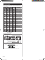
11. ERROR CODES
If you use a wired type remote controller, error codes will appear on the remote controller
display. If you use a wireless remote controller, the lamp on the photodetector unit will
output error codes by way of blinking patterns. See the lamp blinking patterns and error
codes in the table below.
Error indications
Wired remote
controller
error code
Error contents
OPERATION
lamp (green)
TIMER lamp
(orange)
FILTER lamp
(red)
(1) (2)
Remote controller communi-
cation error
(1) (4)
Network communication error
(1) (6)
Peripheral unit communica-
tion error
(2) (6)
Indoor unit address setting
error
(2) (9)
Connection unit number error
in wired remote controller
system
(3) (1)
Indoor unit power supply
abnormal
(3) (2)
Indoor unit main PCB error
(3) (3)
Indoor unit communication
circuit (extension microcom-
puter) error
(3) (10)
Indoor unit communication
circuit (wired remote control-
ler) error
(4) (1)
Indoor unit room temp. therm-
istor error
(4) (2)
Indoor unit heat ex. temp.
thermistor error
(5) (1)
Indoor unit fan motor 1 error
(5) (2)
Indoor unit coil (expansion
valve) error
(5) (3)
Indoor unit water drain
abnormal
(9) (15)
Outdoor unit miscellaneous
error
(10) (8)
Poor refrigerant circulation
(13) (1)
RB unit error
Display mode
: 0.5 s ON / 0.5 s OFF
: 0.1 s ON / 0.1 s OFF
( ) : Number of flashing
Wired Remote Controller Display
UTY-RLR* (2-wire type)
Error icon
Error icon
Error code
Touch the [Status]. Touch the [Error Information].
For more information, refer to the installation manual of the remote controller.
For more information, refer to the installation manual of the remote controller.
2-digit numbers are corresponding to
the error code in the preceding table.
Touch the [Next Page] (or [previous page])
to switch to other indoor unit information.
UTY-RNR*Z* (2-wire type)
9383489013_IM.indb 139383489013_IM.indb 13 08-Feb-19 17:11:2708-Feb-19 17:11:27
-
 1
1
-
 2
2
-
 3
3
-
 4
4
-
 5
5
-
 6
6
-
 7
7
-
 8
8
-
 9
9
-
 10
10
-
 11
11
-
 12
12
-
 13
13
-
 14
14


Fujitsu AUXS018GLEH Installation guide
- Category
- Split-system air conditioners
- Type
- Installation guide
- This manual is also suitable for
Ask a question and I''ll find the answer in the document
Finding information in a document is now easier with AI
Related papers
-
Fujitsu AUXK024GLEH Installation guide
-
Fujitsu AUXN014GLAH Installation guide
-
-
-
Fujitsu AUXM030GLAH Installation guide
-
-
Fujitsu AUXK024GLAH Installation guide
-
Fujitsu AUXK054GTAH Installation guide
-
-
Other documents
-
MD Building Products 50148 Installation guide
-
 AirStage ARXC36L Installation guide
-
 AirStage ARUH60RLAV Installation guide
-
Friedrich C24YJ Ductless Split System Warranty
-
 Fraser Hill Farm FSHL013RDA-GN Operating instructions
-
Haunted Hill Farm FSHLJK018A-OR1 Installation guide
-
 Fraser Hill Farm FSHL018SQA-GN Operating instructions
-
ABB PS S18-300 User manual
-
Daikin Wireless Remote Controller Kit User manual
-
Carrier 42hqv035 Owner's manual


