Page is loading ...

2506 Galen Drive
Champaign, IL 61821
Voice 217.344.1243 • Fax 217.344.1245
www.cobaltdigital.com
Product Manual
9933EMDE-75-110-OM (V1.4)
Cobalt Digital Inc.
3G/HD/SD-SDI 16-Channel Unbalanced / Balanced
AES Embedder / De-Embedder
9933-EMDE-75/1109933-EMDE-75/110

Copyright
©Copyright 2019, Cobalt Digital Inc. All Rights Reserved.
Duplication or distribution of this manual and any information contained within is strictly prohibited without the express written
permission of Cobalt Digital Inc. This manual and any information contained within, may not be reproduced, distributed, or
transmitted in any form, or by any means, for any purpose, without the express written permission of Cobalt Digital Inc.
Reproduction or reverse engineering of software used in this device is prohibited.
Disclaimer
The information in this document has been carefully examined and is believed to be entirely reliable. However, no responsibility
is assumed for inaccuracies. Furthermore, Cobalt Digital Inc. reserves the right to make changes to any products herein to improve
readability, function, or design. Cobalt Digital Inc. does not assume any liability arising out of the application or use of any
product or circuit described herein.
Trademark Information
Cobalt
®
is a registered trademark of Cobalt Digital Inc.
openGear
®
is a registered trademark of Ross Video Limited. DashBoard™ is a trademark of Ross Video Limited.
Dolby
®
is a registered trademark of Dolby Laboratories, Inc. Other product names or trademarks appearing in this manual are the
property of their respective owners.
Congratulations on choosing the Cobalt
®
9933-EMDE-75/110 3G/HD/SD-SDI 16-Channel Unbalanced/
Balanced AES Embedder / De-Embedder. The 9933-EMDE-75/110 is part of a full line of modular processing
and conversion gear for broadcast TV environments. The Cobalt Digital Inc. line includes video decoders and
encoders, audio embedders and de-embedders, distribution amplifiers, format converters, remote control
systems and much more. Should you have questions pertaining to the installation or operation of your
9933-EMDE-75/110 card, please contact us at the contact information on the front cover.
Manual No.: 9933EMDE-75-110-OM
Document Version: V1.4
Release Date: January 9, 2019
Applicable for
Firmware Version
(or greater):
v1.4.6
Description of
product/manual
changes:
- Remove options no longer applicable to product.
- Revise for manual consistency updates.
9933EMDE-75-110-OM (V1.4)

9933EMDE-75-110-OM (V1.4) 9933-EMDE-75/110 PRODUCT MANUAL i
Table of Contents
Chapter 1 Introduction . . . . . . . . . . . . . . . . . . . . . . . . . . . . . . . . . . . . . . . . . . . 1-1
Overview ................................................................................................................ 1-1
9933-EMDE-75/110 Card Software Versions and this Manual............................. 1-2
Cobalt Reference Guides........................................................................................ 1-2
Manual Conventions............................................................................................... 1-3
Warnings, Cautions, and Notes .................................................................. 1-4
Labeling Symbol Definitions...................................................................... 1-4
Safety and Regulatory Summary............................................................................ 1-5
Warnings..................................................................................................... 1-5
Cautions...................................................................................................... 1-5
EMC Compliance Per Market .................................................................... 1-5
9933-EMDE-75/110 Functional Description ......................................................... 1-6
9933-EMDE-75/110 Input/Output Formats ............................................... 1-6
Audio Processor Description...................................................................... 1-7
User Control Interface ................................................................................ 1-7
9933-EMDE-75/110 Rear I/O Modules ..................................................... 1-9
Technical Specifications......................................................................................... 1-9
Contact Cobalt Digital Inc.................................................................................... 1-10
Warranty and Service Information ....................................................................... 1-11
Cobalt Digital Inc. Limited Warranty....................................................... 1-11
Chapter 2 Installation and Setup . . . . . . . . . . . . . . . . . . . . . . . . . . . . . . . . . . . 2-1
Overview ................................................................................................................ 2-1
Installing the 9933-EMDE-75/110 Into a Frame Slot............................................ 2-1
Installing a Rear I/O Module.................................................................................. 2-3
9933-EMDE-75/110 Rear I/O Modules ..................................................... 2-4
Setting Up 9933-EMDE-75/110 Network Remote Control................................... 2-5
Chapter 3 Operating Instructions. . . . . . . . . . . . . . . . . . . . . . . . . . . . . . . . . . . 3-1
Overview ................................................................................................................ 3-1
Control and Display Descriptions........................................................................... 3-1
Function Menu/Parameter Overview.......................................................... 3-2
DashBoard™ User Interface....................................................................... 3-3
Accessing the 9933-EMDE Card via Remote Control........................................... 3-4
Accessing the 9933-EMDE Card Using DashBoard™.............................. 3-4
Checking 9933-EMDE Card Information .............................................................. 3-6
9933-EMDE Function Menu List and Descriptions............................................... 3-7

ii 9933-EMDE-75/110 PRODUCT MANUAL 9933EMDE-75-110-OM (V1.4)
Input Audio Status ...................................................................................... 3-8
Output Audio Routing ................................................................................ 3-9
Troubleshooting .................................................................................................... 3-12
Error and Failure Indicator Overview....................................................... 3-12
Basic Troubleshooting Checks.................................................................. 3-15
9933-EMDE Processing Error Troubleshooting....................................... 3-15
Troubleshooting Network/Remote Control Errors.................................... 3-16
In Case of Problems .................................................................................. 3-16

9933EMDE-75-110-OM (V1.4) 9933-EMDE16-75/110 PRODUCT MANUAL 1-1
Chapter 1
Chapter 1 Introduction
Overview
This manual provides installation and operating instructions for the
9933-EMDE-75/110 3G/HD/SD-SDI 16-Channel Unbalanced/Balanced AES
Embedder / De-Embedder card (also referred to herein as the
9933-EMDE-75/110).
This manual consists of the following chapters:
• Chapter 1, “Introduction” – Provides information about this manual
and what is covered. Also provides general information regarding the
9933-EMDE-75/110.
• Chapter 2, “Installation and Setup” – Provides instructions for
installing the 9933-EMDE-75/110 in a frame, and optionally
installing a Rear I/O Module(s).
• Chapter 3, “Operating Instructions” – Provides overviews of
operating controls and instructions for using the 9933-EMDE-75/110.
This chapter contains the following information:
• 9933-EMDE-75/110 Card Software Versions and this Manual (p.
1-2)
• Manual Conventions (p. 1-3)
• Safety and Regulatory Summary (p. 1-5)
• 9933-EMDE-75/110 Functional Description (p. 1-6)
• Technical Specifications (p. 1-9)
• Warranty and Service Information (p. 1-11)
• Contact Cobalt Digital Inc. (p. 1-10)

1 9933-EMDE-75/110 Card Software Versions and this Manual
1-2 9933-EMDE16-75/110 PRODUCT MANUAL 9933EMDE-75-110-OM (V1.4)
9933-EMDE-75/110 Card Software Versions and this Manual
When applicable, Cobalt Digital Inc. provides for continual product
enhancements through software updates. As such, functions described in this
manual may pertain specifically to cards loaded with a particular software
build.
The Software Version of your card can be checked by viewing the Card Info
menu in DashBoard™. See Checking 9933-EMDE Card Information (p. 3-6)
in Chapter 3, “Operating Instructions” for more information. You can then
check our website for the latest software version currently released for the
card as described below.
Note: Not all functionality described in this manual may appear on cards with initial
software versions.
Check our website and proceed as follows if your card’s software does not
match the latest version:
Cobalt Reference Guides
From the Cobalt
®
web home page, go to Support>Reference Documents for
easy to use guides covering network remote control, card firmware updates,
example card processing UI setups and other topics.
Card Software earlier than
latest version
Card is not loaded with the latest software. Not all
functions and/or specified performance described in
this manual may be available.
You can update your card with new Update software by
going to the Support>Firmware Downloads link at
www.cobaltdigital.com. Download “Firmware Update
Guide”, which provides simple instructions for
downloading the latest firmware for your card onto your
computer, and then uploading it to your card through
DashBoard™.
Software updates are field-installed without any
need to remove the card from its frame.
Card Software newer than
version in manual
A new manual is expediently released whenever a
card’s software is updated and specifications
and/or functionality have changed as compared to
an earlier version (a new manual is not necessarily
released if specifications and/or functionality have not
changed). A manual earlier than a card’s software
version may not completely or accurately describe all
functions available for your card.
If your card shows features not described in this
manual, you can check for the latest manual (if
applicable) and download it by going to the card’s web
page on www.cobaltdigital.com.

9933EMDE-75-110-OM (V1.4) 9933-EMDE16-75/110 PRODUCT MANUAL 1-3
Introduction Manual Conventions
Manual Conventions
In this manual, display messages and connectors are shown using the exact
name shown on the 9933-EMDE-75/110 itself. Examples are provided below.
• Card-edge display messages are shown like this:
• Connector names are shown like this: SDI IN A
In this manual, the terms below are applicable as follows:
• 9933-EMDE-75/110 refers to the 9933-EMDE-75/110 3G/HD/
SD-SDI 16-Channel Unbalanced/Balanced AES Embedder /
De-Embedder card.
• Frame refers to the HPF-9000, OG3-FR, 8321, or similar 20-slot
frame that houses Cobalt
®
or other cards.
• Device and/or Card refers to a Cobalt
®
or other card.
• System and/or Video System refers to the mix of interconnected
production and terminal equipment in which the 9933-EMDE-75/110
and other cards operate.
• Functions and/or features that are available only as an option are
denoted in this manual like this:
BOOT

1 Manual Conventions
1-4 9933-EMDE16-75/110 PRODUCT MANUAL 9933EMDE-75-110-OM (V1.4)
Warnings, Cautions, and Notes
Certain items in this manual are highlighted by special messages. The
definitions are provided below.
Warnings
Warning messages indicate a possible hazard which, if not avoided, could
result in personal injury or death.
Cautions
Caution messages indicate a problem or incorrect practice which, if not
avoided, could result in improper operation or damage to the product.
Notes
Notes provide supplemental information to the accompanying text. Notes
typically precede the text to which they apply.
Labeling Symbol Definitions
Important note regarding product usage. Failure to observe may result in
unexpected or incorrect operation.
Electronic device or assembly is susceptible to damage from an ESD
event. Handle only using appropriate ESD prevention practices.
If ESD wrist strap is not available, handle card only by edges and avoid
contact with any connectors or components.
Symbol (WEEE 2002/96/EC)
For product disposal, ensure the following:
• Do not dispose of this product as unsorted municipal waste.
• Collect this product separately.
• Use collection and return systems available to you.

9933EMDE-75-110-OM (V1.4) 9933-EMDE16-75/110 PRODUCT MANUAL 1-5
Introduction Safety and Regulatory Summary
Safety and Regulatory Summary
Warnings
Cautions
EMC Compliance Per Market
! WARNING !
To reduce risk of electric shock do not remove line voltage service barrier cover on frame
equipment containing an AC power supply. NO USER SERVICEABLE PARTS INSIDE.
REFER SERVICING TO QUALIFIED SERVICE PERSONNEL.
CAUTION
This device is intended for environmentally controlled use only in appropriate video
terminal equipment operating environments.
CAUTION
This product is intended to be a component product of an openGear® frame. Refer to the
openGear® frame Owner's Manual for important safety instructions regarding the proper
installation and safe operation of the frame as well as its component products.
CAUTION
Heat and power distribution requirements within a frame may dictate specific slot
placement of cards. Cards with many heat-producing components should be arranged to
avoid areas of excess heat build-up, particularly in frames using only convection cooling.
The card has a moderate power dissipation (<18 W). As such, avoiding placing the card
adjacent to other cards with similar dissipation values if possible.
CAUTION
If required, make certain Rear I/O Module(s) is installed before installing the card into the
frame slot. Damage to card and/or Rear I/O Module can occur if module installation is
attempted with card already installed in slot.
CAUTION
If card resists fully engaging in rear I/O module mating connector, check for alignment and
proper insertion in slot tracks. Damage to card and/or rear I/O module may occur if
improper card insertion is attempted.
Market Regulatory Standard or Code
United States of America FCC "Code of Federal Regulations" Title 47 Part 15, Subpart B, Class A
Canada ICES-003
International/CE CISPR 24:2010
IEC 61000-4-2:2008
IEC 61000-4-3:2006 with A1:2007 and A2:2010
IEC 61000-4-4:2004
IEC 61000-4-6:2008
CISPR 22:2008

1 9933-EMDE-75/110 Functional Description
1-6 9933-EMDE16-75/110 PRODUCT MANUAL 9933EMDE-75-110-OM (V1.4)
9933-EMDE-75/110 Functional Description
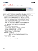
Figure 1-1 shows a functional block diagram of the 9933-EMDE-75/110. The
card provides de-embedding or embedding between 75Ω unbalanced
AES-3id and 110Ω balanced AES/EBU professional balanced digital audio
and SMPTE embedded audio using full 24-bit conversion. In addition to
individual per-pair embedding or de-embedding, the card can be used to
provide cross-balun I/O functions. Full audio crosspoints allow per-channel
gain and routing controls, as well as built-in tone generators. GUI audio
meters provide ready assessment of content presence and line-up.
9933-EMDE-75/110 Input/Output Formats
The 9933-EMDE-75/110 provides the following inputs and outputs:
• Inputs:
• 3G/HD/SD SDI IN – 3G/HD/SD-SDI coaxial input.
• AES I/O – Up to 16 channels (8 pairs) of embedding inputs from
either unbalanced or balanced AES sources.
• Outputs:
• 3G/HD/SD-SDI OUT – 3G/HD/SD-SDI coaxial output.
• AES I/O – Up to 16 channels (8 pairs) of de-embedded outputs to
either unbalanced or balanced AES.
Figure 1-1 9933-EMDE-75/110 Functional Block Diagrams
9933-EMDE-75-110 BD V 1.0LB123
3G/HD/SD-SDI
SDI Tx/
Driver
AES Tx
SDI Rx/
Audio
De-Embed
Audio
Channel
Routing/
Control
3G/HD/SD-SDI
OUT
Audio
Embed
AES Rx
SRC
(Per-Pair auto-detect
bypass for Dolby pair)
AES Per-Pair
Direction
Control
Unbalanced
AES I/0
(16-Ch max)
Balanced AES I/0
(16-Ch max)

9933EMDE-75-110-OM (V1.4) 9933-EMDE16-75/110 PRODUCT MANUAL 1-7
Introduction 9933-EMDE-75/110 Functional Description
Audio Processor Description
The audio processor operates as an internal audio router. This function
chooses from the following inputs:
• 16 channels of embedded audio from the SDI video input (default
1-to-1 routing to SDI output)
• Up to 16 channels (8 pairs) of AES-3id or AES/EBU audio inputs or
outputs between AES I/O ports and embedded audio
The audio processing subsection is built around a card internal 16-channel
audio bus. Audio embed adaptive SRC allows asynchronous 48 kHz AES
audio to automatically sync with program video 48 kHz timing for glitch-free
embedding. Individual, per-pair SRC auto-detects and disables SRC when a
Dolby pair is detected on an input pair.
Audio status (presence, dBFS signal levels) is displayed for each embedded
and AES input channel.
User Control Interface
Figure 1-2 shows the user control interface options for the 9933-EMDE-75/
110. These options are individually described below.
Note: All user control interfaces described here are cross-compatible and can oper-
ate together as desired. Where applicable, any control setting change made
using a particular user interface is reflected on any other connected interface.
• DashBoard™ User Interface – Using DashBoard™, the
9933-EMDE-75/110 and other cards installed in openGear®
1
frames
can be controlled from a computer and monitor.
DashBoard™ allows users to view all frames on a network with
control and monitoring for all populated slots inside a frame. This
simplifies the setup and use of numerous modules in a large
installation and offers the ability to centralize monitoring. Cards
define their controllable parameters to DashBoard™, so the control
interface is always up to date.
The DashBoard™ software can be downloaded from the Cobalt
Digital Inc. website: www.cobaltdigital.com
(enter “DashBoard” in
the search window). The DashBoard™ user interface is described in
Chapter 3,“Operating Instructions”.
1. openGear® is a registered trademark of Ross Video Limited. DashBoard™ is a trademark of Ross
Video Limited.

1 9933-EMDE-75/110 Functional Description
1-8 9933-EMDE16-75/110 PRODUCT MANUAL 9933EMDE-75-110-OM (V1.4)
• Cobalt
®
OGCP-9000 and OGCP-9000/CC Remote Control
Panels – The OGCP-9000 and OGCP-9000/CC Remote Control
Panels conveniently and intuitively provide parameter monitor and
control of the 9933-EMDE-75/110 and other video and audio
processing terminal equipment meeting the open-architecture Cobalt
®
cards for openGear™ standard.
In addition to circumventing the need for a computer to monitor and
control signal processing cards, the Control Panels allow quick and
intuitive access to hundreds of cards in a facility, and can monitor and
allow adjustment of multiple parameters at one time.
The Remote Control Panels are totally compatible with the
openGear™ control software DashBoard™; any changes made with
either system are reflected on the other.
Figure 1-2 9933-EMDE-75/110 User Control Interface
Computer
with NIC
OGCP-9000 Control Panel
or
OGCP-9000/CC Control Panel
20-Slot Frame with Network Controller Card
LAN
9933-EMDE-75/110
Card
In conjunction with a frame equipped
with a Network Controller Card,
9933-EMDE-75/110 card can be
remotely controlled over a LAN
Remote Control Panel
Using the Control Panel, 9933-EMDE-75/110
card can be remotely controlled over a LAN
DashBoard™ Remote Control
Using a computer with DashBoard™
installed, 9933-EMDE-75/110 card
can be remotely controlled over a
LAN
Note: • To communicate with DashBoard™ or a Remote Control Panel, the frame must have a Network Controller Card
(MFC-8320-N, MFC-FC, or equivalent) installed in the frame.
• DashBoard™ and the Remote Control Panels provide network control of the 9933-EMDE-75/110 as shown. The value
displayed at any time on the card, or via DashBoard™ or a Control Panel is the actual value as set on the card, with the
current value displayed being the actual value as effected by the card. Parameter changes made by any of these means
are universally accepted by the card (for example, a change made using the DashBoard™ controls will change the setting
displayed on a Control Panel).

9933EMDE-75-110-OM (V1.4) 9933-EMDE16-75/110 PRODUCT MANUAL 1-9
Introduction Technical Specifications
Note: If network remote control is to be used for the frame and the frame has not yet
been set up for remote control, Cobalt
®
reference guide Remote Control
User Guide (PN 9000RCS-RM) provides thorough information and
step-by-step instructions for setting up network remote control of Cobalt
®
cards using DashBoard™. (Cobalt
®
OGCP-9000 and OGCP-9000/CC
Remote Control Panel product manuals have complete instructions for setting
up remote control using a Remote Control Panel.)
Download a copy of this guide by clicking on the Support>Reference
Documents link at www.cobaltdigital.com and then select DashBoard
Remote Control Setup Guide as a download, or contact Cobalt
®
as listed in
Contact Cobalt Digital Inc. (p. 1-10).
9933-EMDE-75/110 Rear I/O Modules
The 9933-EMDE-75/110 physically interfaces to system video connections at
the rear of its frame using a Rear I/O Module.
All inputs and outputs shown in the 9933-EMDE-75/110 Functional Block
Diagrams (Figure 1-1) enter and exit the card via the card edge backplane
connector. The Rear I/O Module breaks out the 9933-EMDE-75/110 card
edge connections to BNC and other connectors that interface with other
components and systems in the signal chain.
The full assortment of 9933-EMDE-75/110 Rear I/O Modules is shown and
described in 9933-EMDE-75/110 Rear I/O Modules (p. 2-4) in Chapter 2,
“Installation and Setup”.
Technical Specifications
Table 1-1 lists the technical specifications for the 9933-EMDE-75/110 3G/
HD/SD-SDI 16-Channel Unbalanced/Balanced AES Embedder /
De-Embedder card.
Table 1-1 Technical Specifications
Item Characteristic
Part number, nomenclature 9933-EMDE-75/110 3G/HD/SD-SDI 16-Channel Unbalanced/
Balanced AES Embedder / De-Embedder
Installation/usage environment Intended for installation and usage in frame meeting openGear™
modular system definition
Power consumption < 18 Watts maximum
Installation Density Up to 20 cards per 20-slot frame
Environmental:
Operating temperature:
Relative humidity (operating or storage):
32° – 104° F (0° – 40° C)
< 95%, non-condensing
Frame communication 10/100/1000 Mbps Ethernet with Auto-MDIX

1 Contact Cobalt Digital Inc.
1-10 9933-EMDE16-75/110 PRODUCT MANUAL 9933EMDE-75-110-OM (V1.4)
Contact Cobalt Digital Inc.
Feel free to contact our thorough and professional support representatives for
any of the following:
• Name and address of your local dealer
• Product information and pricing
• Technical support
• Upcoming trade show information
Indicators Card edge display and indicators as follows:
• Status/Error LED indicator
• Input Presence (3G/HD/SD) LED indicators
SDI Inputs/Outputs (1) 75Ω BNC input
(1) 75Ω BNC output
SDI Receive Cable Length (1694A): 120m/180m/360m
(3G/HD/SD)
SDI Return Loss: >15 dB up to 1.485 GHz; >10 dB up to
2.970 GHz
Note: SDI Return loss and receive cable length are affected by
rear I/O module used. Specifications represent typical
performance.
Alignment Jitter: 3G/HD/SD: < 0.3/0.2/0.2 UI
Timing Jitter: 3G/HD/SD: < 2.0/1.0/0.2 UI
SDI Formats Supported: SMPTE 259M, SMPTE 292M,
SMPTE 424M
Audio Conversion Format 48 kHz sampling, 24-bit. Auto-SRC bypass for Dolby inputs.
AES Audio Input/Output (8-pair) Unbalanced AES-3id audio input/outputs with per-pair port
direction controls, Input Impedance: 75 Ω
(8-pair) Balanced AES/EBU audio input/outputs with per-pair port
direction controls, Input Impedance: 110 Ω
Table 1-1 Technical Specifications — continued
Item Characteristic
Phone: (217) 344-1243
Fax: (217) 344-1245
Web: www.cobaltdigital.com
General Information: info@cobaltdigital.com
Technical Support: support@cobaltdigital.com

9933EMDE-75-110-OM (V1.4) 9933-EMDE16-75/110 PRODUCT MANUAL 1-11
Introduction Warranty and Service Information
Warranty and Service Information
Cobalt Digital Inc. Limited Warranty
This product is warranted to be free from defects in material and workmanship for a period of five (5)
years from the date of shipment to the original purchaser, except that 4000, 5000, 6000, 8000 series
power supplies, and Dolby
®
modules (where applicable) are warranted to be free from defects in
material and workmanship for a period of one (1) year.
Cobalt Digital Inc.'s (“Cobalt”) sole obligation under this warranty shall be limited to, at its option, (i)
the repair or (ii) replacement of the product, and the determination of whether a defect is covered under
this limited warranty shall be made at the sole discretion of Cobalt.
This limited warranty applies only to the original end-purchaser of the product, and is not assignable or
transferrable therefrom. This warranty is limited to defects in material and workmanship, and shall not
apply to acts of God, accidents, or negligence on behalf of the purchaser, and shall be voided upon the
misuse, abuse, alteration, or modification of the product. Only Cobalt authorized factory
representatives are authorized to make repairs to the product, and any unauthorized attempt to repair
this product shall immediately void the warranty. Please contact Cobalt Technical Support for more
information.
To facilitate the resolution of warranty related issues, Cobalt recommends registering the product by
completing and returning a product registration form. In the event of a warrantable defect, the
purchaser shall notify Cobalt with a description of the problem, and Cobalt shall provide the purchaser
with a Return Material Authorization (“RMA”). For return, defective products should be double boxed,
and sufficiently protected, in the original packaging, or equivalent, and shipped to the Cobalt Factory
Service Center, postage prepaid and insured for the purchase price. The purchaser should include the
RMA number, description of the problem encountered, date purchased, name of dealer purchased
from, and serial number with the shipment.
Cobalt Digital Inc. Factory Service Center
2506 Galen Drive Office: (217) 344-1243
Champaign, IL 61821 USA Fax: (217) 344-1245
www.cobaltdigital.com Email: info@cobaltdigital.com
THIS LIMITED WARRANTY IS EXPRESSLY IN LIEU OF ALL OTHER WARRANTIES
EXPRESSED OR IMPLIED, INCLUDING THE WARRANTIES OF MERCHANTABILITY AND
FITNESS FOR A PARTICULAR PURPOSE AND OF ALL OTHER OBLIGATIONS OR
LIABILITIES ON COBALT'S PART. ANY SOFTWARE PROVIDED WITH, OR FOR USE WITH,
THE PRODUCT IS PROVIDED “AS IS.” THE BUYER OF THE PRODUCT ACKNOWLEDGES
THAT NO OTHER REPRESENTATIONS WERE MADE OR RELIED UPON WITH RESPECT TO
THE QUALITY AND FUNCTION OF THE GOODS HEREIN SOLD. COBALT PRODUCTS ARE
NOT AUTHORIZED FOR USE IN LIFE SUPPORT APPLICATIONS.
COBALT'S LIABILITY, WHETHER IN CONTRACT, TORT, WARRANTY, OR OTHERWISE, IS
LIMITED TO THE REPAIR OR REPLACEMENT, AT ITS OPTION, OF ANY DEFECTIVE
PRODUCT, AND SHALL IN NO EVENT INCLUDE SPECIAL, INDIRECT, INCIDENTAL, OR
CONSEQUENTIAL DAMAGES (INCLUDING LOST PROFITS), EVEN IF IT HAS BEEN
ADVISED OF THE POSSIBILITY OF SUCH DAMAGES.

1-12 9933-EMDE16-75/110 PRODUCT MANUAL 9933EMDE-75-110-OM (V1.4)
This page intentionally blank

9933EMDE-75-110-OM (V1.4) 9933-EMDE16-75/110 PRODUCT MANUAL 2-1
Chapter 2
Chapter 2 Installation and Setup
Overview
This chapter contains the following information:
• Installing the 9933-EMDE-75/110 Into a Frame Slot (p. 2-1)
• Installing a Rear I/O Module (p. 2-3)
• Setting Up 9933-EMDE-75/110 Network Remote Control (p. 2-5)
Installing the 9933-EMDE-75/110 Into a Frame Slot
CAUTION
Heat and power distribution requirements within a frame may dictate specific
slot placement of cards. Cards with many heat-producing components should
be arranged to avoid areas of excess heat build-up, particularly in frames
using only convection cooling. The card has a moderate power dissipation
(<18 W). As such, avoiding placing the card adjacent to other cards with
similar dissipation values if possible.
CAUTION
Note: If installing the card in a slot with no rear I/O module, a Rear I/O Module
is required before cabling can be connected. Refer to Installing a Rear I/O
Module (p. 2-3) for rear I/O module installation procedure.
CAUTION
If required, make certain Rear I/O Module(s) is installed before installing the
card into the frame slot. Damage to card and/or Rear I/O Module can occur if
module installation is attempted with card already installed in slot.
This device contains semiconductor devices which are
susceptible to serious damage from Electrostatic
Discharge (ESD). ESD damage may not be immediately
apparent and can affect the long-term reliability of the
device.
Avoid handling circuit boards in high static environments
such as carpeted areas, and when wearing synthetic fiber
clothing. Always use proper ESD handling precautions
and equipment when working on circuit boards and
related equipment.

2 Installing the 9933-EMDE-75/110 Into a Frame Slot
2-2 9933-EMDE16-75/110 PRODUCT MANUAL 9933EMDE-75-110-OM (V1.4)
Note: Check the packaging in which the card was shipped for any extra items such
as a Rear I/O Module connection label. In some cases, this label is shipped
with the card and to be installed on the Rear I/O connector bank correspond-
ing to the slot location of the card.
Install the card into a frame slot as follows:
1. Determine the slot in which the card is to be installed.
2. Open the frame front access panel.
3. While holding the card by the card edges, align the card such that the
plastic ejector tab is on the bottom.
4. Align the card with the top and bottom guides of the slot in which the
card is being installed.
5. Gradually slide the card into the slot. When resistance is noticed, gently
continue pushing the card until its rear printed circuit edge terminals
engage fully into the rear I/O module mating connector.
CAUTION
If card resists fully engaging in rear I/O module mating connector, check for
alignment and proper insertion in slot tracks. Damage to card and/or rear I/O
module may occur if improper card insertion is attempted.
6.
Verify that the card is fully engaged in rear I/O module mating
connector.
7. Close the frame front access panel.
8. Connect the input and output cables as shown in 9933-EMDE-75/110
Rear I/O Modules (p. 2-4).
9. Repeat steps 1 through 8 for other cards.
Note: • The card BNC inputs are internally 75-ohm terminated. It is not necessary to
terminate unused BNC inputs or outputs.
• To remove a card, press down on the ejector tab to unseat the card from the
rear I/O module mating connector. Evenly draw the card from its slot.
10. If network remote control is to be used for the frame and the frame has
not yet been set up for remote control, perform setup in accordance with
Setting Up 9933-EMDE-75/110 Network Remote Control (p. 2-5).
Note: If installing a card in a frame already equipped for, and connected to
DashBoard™, no network setup is required for the card. The card will be dis-
covered by DashBoard™ and be ready for use.

9933EMDE-75-110-OM (V1.4) 9933-EMDE16-75/110 PRODUCT MANUAL 2-3
Installation and Setup Installing a Rear I/O Module
Installing a Rear I/O Module
Note: This procedure is applicable only if a Rear I/O Module is not currently
installed in the slot where the card is to be installed.
If installing the card in a slot already equipped with a suitable I/O module,
omit this procedure.
Install a Rear I/O Module as follows:
1. On the frame, determine the slot in which the card is to be installed.
2. In the mounting area corresponding to the slot location, install
Rear I/O Module as shown in Figure 2-1.
Figure 2-1 Rear I/O Module Installation
Align and engage mounting tab on Rear
I/O Module with the module seating slot
on rear of frame chassis.
Hold top of Rear I/O Module flush against
frame chassis and start the captive screw.
Lightly tighten captive screw.
1
2

2 Installing a Rear I/O Module
2-4 9933-EMDE16-75/110 PRODUCT MANUAL 9933EMDE-75-110-OM (V1.4)
9933-EMDE-75/110 Rear I/O Modules
Table 2-1 shows and describes the full assortment of Rear I/O Modules
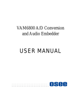
specifically for use with the 9933-EMDE-75/110. Figure 2-2 shows how to
connect wiring to removable multipin connectors.
Figure 2-2 Balanced Audio Connector Pinouts
Table 2-1 9933-EMDE-75/110 Rear I/O Modules
9933-EMDE-75/110 Rear I/O Module Description
RM20-9933EMDE-A Provides the following connections:
• One 3G/HD/SD-SDI input BNC (SDI IN)
• Eight AES/EBU balanced audio input/outputs
(BAL AES AUD I/O 1 thru AES AUD I/O 8)
• Eight AES-3id unbalanced audio input/outputs
(UNBAL AES AUD I/O 1 thru AES AUD I/O 8)
• One 3G/HD/SD-SDI output BNC (SDI OUT)
Note: AES coaxial connectors are HD-BNC or
DIN1.0/2.3. Available equipped with
High-Density BNC (HDBNC) or DIN1.0/2.3
connectors as:
RM20-9933EMDE-A-HDBNC or
RM20-9933EMDE-A-DIN, respectively.
+
–
G
Removable multipin plug
view oriented with orange
release buttons to the left
Note: • Press orange release button to insert wires
into holes.
• Wire thinner than 24 AWG may not be
securely retained in connector.
• The G terminal is shared by both ports.
Depending on wire gauge, two wires may not
fit in insertion hole. In this case, make the
bridge connection external to the multipin
plug.
Rear module
PCB connector
+
–
G
+
–
+
–
G
Wiring insertion
holes
/