Thermo Pride AOPS7463, AOPS7465, AOPS7466, AOPS7467, AOPS7468, AOPS7469, AOPS7470, AOPS7479, AOPS7475, AOPS7476 Owner's manual

Type
Owner's manual
MO-459
ECN 5647-MA 200813 1
ECM CONVERSION KIT INSTALLATION INSTRUCTIONS
I. REMOVAL OF ORIGINAL BELT OR DIRECT DRIVE BLOWER ASSEMBLY
A. Turn off power to the unit.
B. Disconnect power to the unit.
C. Remove Fan & Limit from the unit. Dis-connect wiring to Fan & Limit. Dis-connect T-
Stat wire from R & W on the Fan Center that goes to T & T on the Oil Primary. Remove
Oil Primary from the burner and dis-connect the Blue & White wires from the harness
(L1 & L2). Loosen Strain Relief and pull SJT cable through Strain Relief leaving Strain
Relief in place.
D. Dis-connect Blower Cable from the Blower Assembly.
E. Remove Blower hold-downs (save screws) and remove Blower Assembly.
F. Pull Blower Cables through the Rear Separator and out the front of the vestibule.
G. Un-screw 4 x 4 box from casing & remove the wire harness. The Fan & Limit and Heyco
bushing must be saved, as they will be used with the new ECM Assembly.
IMPORTANT: Retain all screws and cable clamps from the old blower so they can be used in
the installation of the new ECM blower and Control Panel Assembly.
II. INSTALLATION OF ECM BLOWER CONVERSION
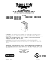
A. Examine all items needed for ECM conversion for shipping damage and to be sure all
parts needed for the conversion were included in the kit. Fig. 1 shows all items needed for
the lowboy conversion. For a lowboy unit each kit will contain, 1 ECM blower assembly,
1 ECM control panel assembly and blower block-offs. For a highboy unit each kit will
contain, 1 ECM blower assembly and 1 ECM control panel assembly. NOTE: Blower
Block offs are included in all lowboy ECM conversion kits to be used in installations
where the original blower opening was larger than the new conversion blower assembly.
If the opening is smaller than the new ECM blower assembly, refer to the Blower
Opening Modification Chart on page 3 of the instruction manual.
B. For a lowboy conversion, place new ECM blower assembly to the left side of the unit on
the floor so as to have enough space to run new blower cables through the holes in the
rear separator and pouch front. Fig. 2. Do not put the blower in it’s mounted place at this
time due to the fact that you will need space to feed wires through the rear separator and
pouch front holes. To convert a Highboy unit, install new blower assembly into proper
location and secure to blower pan with the blower hold-downs used on the original
blower not forgetting to attach the ground wire. Insert the new motor cables through the
hole in the blower pan where the original motor wiring went.
2
C. On a Lowboy unit, before inserting new blower cables through the holes in the rear
separator and pouch front, tape the cable with the blue and white wires, 3” down from the
top of the 6-pin molex plug cable (Fig. 3). Back feed a wire from the vestibule area
through the pouch front and rear separator holes to attach new blower wiring for pulling
wires through to the vestibule.
D. Once you have the new blower assembly wires ran into the vestibule, insert the new ECM
blower conversion into the proper location and install blower hold-downs remembering
to make sure ground wire is re-attached.
E. To install new control panel assembly you must first remove one screw holding the
circuit board to the 4x4 junction box. Open the circuit board that will still be hinged to
the junction box, and with the original nuts and bolts from the original 4x4 box install
new junction box. Fig. 4 and Fig. 5. Re-connect outside power, close cover and replace
screw.
F. Attach fan and limit into original location using screws that were used in the mounting of
the original fan and limit. Fig. 6. Take the Blue/White SJT cable from 9-pin connector
and insert on the limit side of the Fan & Limit (White to the bottom, Blue to the top).
Replace Heyco bushing.
G. NOTE: For wiring refer to the Wiring Diagram or the ECM Operation Manual (MO-
434) supplied with conversion kit. Attach the motor power cable (Blue & White wires) to
the board. The White wire (common) will attach to the #2 terminal on the common strip.
The Blue wire (line voltage) will attach to the S2 terminal. NOTE: On an L16 or L20
conversion, the blue wire will attach to the black wire on the Inductor then the other side
of the Inductor will attach to the S2 terminal.
H. Connect the 6-pin molex plug to the 6-pin plug on the circuit board. Fig. 8
I. Remove the oil primary and connect the White wire from the 9-pin molex plug to the
White wire (L 2) on the oil primary. Connect the Red wire from the 9-pin molex plug to
the black wire (L 1) on the oil primary. Place a wire nut on the Orange wire from the 9-
pin molex plug as it will not be utilized Fig. 9. Install oil primary to the original location
on the oil burner.
J. Connect the two Yellow wires from the 9-pin molex plug to the T & T terminals on the
oil primary. Fig. 10.
K. Make sure the ground wire and cables are secured in their proper locations like they were
in the original blower installation.
3
L. Thermostat wiring; If the t-stat has 5 wires, connect W-to-W, Y-to-Y, G-to-G, put a
jumper between RH and RC at the T-stat then connect R-to-R. If the t-stat has 4 wires,
connect W-to-W, Y-to-Y, G-to-G and R-to-R.
M. Attach new Wiring Diagram to unit. Re-establish power to the unit. Refer to the ECM
Operation Manual (MO-434) for you’re On and Off Blower Delay Time Switch Settings
and CFM Tables. Setting tables for Blower Delay, Heating and Cooling speeds and
temperature rise are listed according to unit. Follow this manual for adjustments and
sequence of operation. Refer to the Oil Fired Furnace Installation and Operation Manual
(MO-100G) to make sure all safety controls are working properly.
BLOWER OPENING MODIFICATION CHART
UNIT SIDE BLOCK OFF
TOP BLOCK OFF TOP CUT OUT
OL2
NONE NONE 1-1/8 x 12-1/2
OH2
NONE NONE NONE
OC2
NONE NONE 1-1/16 x 12-1/2*
OH3
NONE NONE NONE
OL5
NONE NONE 1-1/8 x 12-1/2
OH5****
NONE NONE NONE
OC5
2 x 14 NONE NONE**
OL11
2-1/2 x 14 NONE NONE
OH11
5/8*** NONE NONE
OL16
3-1/4 x 16 3-1/2 x 18 NONE
OL20
3-1/4 x 16 3-1/2 x 18 NONE
*MUST BE CUT OUT TOWARD REAR OF FURNACE.
**BLOWER MUST BE MOUNTED SO THAT SCROLL IS FACING FRONT AND IS EVEN
WITH FRONT EDGE OF BLOWER OPENING.
***EXTEND BLOWER HANGERS BY THIS AMOUNT SO THAT THE BLOWER CAN BE
MOUNTED IN THE EXISTING BRACKETS.
****H5 CANNOT BE CONVERTED FROM 9-9 B.D. TO 11-9T D.D., ONLY FROM 11-9T
B.D. TO 11-9T D.D., IN WHICH CASE NO MODIFICATIONS NEED TO BE MADE TO
THE BLOWER OPENING OR MOUNTING.
4
  • Page 1 1
  • Page 2 2
  • Page 3 3
  • Page 4 4

Thermo Pride AOPS7463, AOPS7465, AOPS7466, AOPS7467, AOPS7468, AOPS7469, AOPS7470, AOPS7479, AOPS7475, AOPS7476 Owner's manual

Type
Owner's manual

Ask a question and I''ll find the answer in the document

Finding information in a document is now easier with AI