Page is loading ...

1
Gasifying boiler VIGAS
Gasifying boilers
MANUAL FOR INSTALLATION, ASSEMBLY,
MAINTENANCE AND USE
Warranty Certificate
VIMAR 201
7
Ver.D 2.00
VIGAS and VIGAS
Lambda Control
with AK 4000 control

2
Gasifying boiler Vigas
Content
Declaration of conformity........................................................................................................
1. Technical description........................................................................................................
2. Technical data...................................................................................................................
3. AK 4000 control description...............................................................................................
4. VIGAS boiler - basic configuration.....................................................................................
5. VIGAS boiler - discharge fan confirguration......................................................................
6. VIGAS
Lambda Control
– basic configuration..............................................................................
7. Kotol VIGAS
Lambda Control
- discharge fan configuration.......................................................
8. Temperature setting............................................................................................................
9. Parametres setting...............................................................................................................
10. Time set-up..........................................................................................................................
11. Harware and software information.......................................................................................
12. Error notification...................................................................................................................
13. Configuration setting using PIN 0000...................................................................................
14. Operating instructions...........................................................................................................
15. Boiler maintenance and repairs............................................................................................
16. Boiler accessories and assembly..........................................................................................
17. Service departments.............................................................................................................
18. Problems, cause and solution..............................................................................................
19. Installation instruction............................................................................................................
Electric schema.....................................................................................................................
VIGAS Warranty certificate....................................................................................................
VIGAS Commisssion certificate ............................................................................................
Page
3
4
5
7
9
10
11
13
14
15
16
16
16
17
22
24
26
27
28
30
32
33
33

3
Gasifying boiler VIGAS
DECLARATION OF CONFORMITY
Issued according to § 12 sec. 3 let. a) Act. No. 264/1999 Coll
a 97 / 23 EC
We, Pavel Vigaš - VIMAR,
It is hereby declared that the undermentioned products comply with technical regulations and the products
are safe if predetermined guidelines are followed. All possible measures have been taken to assure the
compliance of products together with technical documentation are within specification and legal
requirementrs. The validity of this statement is void if unauthorized changes are made without permission
of VIMAR.
Product:
Thermal boiler VIGAS a VIGAS
Lambda Control
with AK4000
control
Type:
VIGAS 16, VIGAS 16
Lambda Control
, VIGAS 25, VIGAS 25
Lambda Control
VIGAS 40, VIGAS 40
Lambda Control
, VIGAS 60, VIGAS 60
Lambda Control
VIGAS 80, VIGAS 80
Lambda Control
, VIGAS 100, VIGAS 100
Lambda Control
VIGAS 29 UD
Producer:
Pavel Vigaš - VIMAR
M. Čulena 25, 974 11 Banská Bystrica,
SLOVAKIA
Competent statutory codes (CSC)
CSC no. 576/2002 C.s. – Pressure Equipment Directive (97/23/EC)
CSC no. 308/2004 C.s. – Low voltage electric devices (2006/95/ES)
CSC no. 194/2005 C.s. – Electromagnetic Compatibility Directive (2004/108/EC)
Used harmonized standards for CE marking
STN EN 303-5: 2012; STN EN 60335-1: 2012; STN EN 60335-2-102/A1 : 2010
STN EN 61000-6-3/A1/AC; STN EN 55014-1/A2: 2012; STN EN 61000-3-2/A2: 2010
STN EN 61000-3-3: 20147; STN EN 61000-6-2
Additional data:
Following certificates were used for conformity assessment:
Design Examination Certificate no. 812990017, no.812990016, Certificate no. 00029/104/2/2009,
Certificate no. 812990019, Certificate no. 101299028, Certificate no. 0006/104/2017, Certificate no.
0007/104/2017, Certificate no. 0015/104/2015, Certifikát č. 0003/104/2016, Certifikát č.
0004/104/2016, Certifikát č. 0005/104/2016, Certifikát č. 0006/104/2016.
CE marking was proceed according to § 13, par. 3 letter a) Act. No. 264/1999 Coll.
Issued in:
Banská Bystrica
Name:
VIGAŠ Pavel
Date of issue:
24.04.2017
Title: Owner
Signature:
M. Čulena 25
974 11 Banská Bystrica
SLOVAKIA
VAT no. SK1020548001
REG no. 17956145

4
Gasifying boiler Vigas
1. TECHNICAL DESCRIPTION
VIGAS thermal boilers are designed for the combustion of dry wood materials, using sawdust to wood logs
according to the dimensions of the gasification chamber, with a maximum diameter of 20 cm. Sawdust,
woodchips, splinters and cuttings must be burned in conjunction with wood logs. Thermal boiler VIGAS 29
UD is designed to burn brown coal. It is possible to use dry wooden material as a substitute fuel.
Boilers are welded from 4 – 6 mm steel sheets. Inner boiler sheets, which are in contact with boiler waste
gases, are 6 mm thick, others are made of 4 mm steel.
The heat exchanger is welded from steel pipes, 57x4,5 mm. Exterior boiler panels are made of 0,8 mm
sheet. Thermal insulation of the boiler is made of insulation material, NOBASIL 20 and 50 mm thickness.
Combustion gases pass through the steel boiler neck to the chimney.
The boiler space consists of a combustion chamber, where fuel is dried and gasified. Then accrued gases
pass through the fireproof concrete nozzle or a cast iron nozzle into the combustion chamber, where it
burns with the help of secondary air. Flue gases are intensively cooled in the exchanger. The boiler has
a light up damper controlled by a lever at the front of the boiler.
In order that the boiler complies with the requirements for non-demanding operations, it is equipped with an
AK4000 control located on the top panel of the boiler. The design of the system allows very effective
combustion of various kinds of fuel. The AK4000 Control with graphical display in basic configuration offers
the following:
controlled temperature of heated water ranging from 70 - 85°C (up to 90°C with accu. tank)
continuous and automatic control of the fan according to required output and type of fuel
connnection to and control of discharge fan
connection to and control of circulation pump
connection to the gases thermometer
connection to room thermostat (room temperature regulator is voltage free )
connection to extended regulation (Expander AK 4000) via BH BUS
connection to module AK 4000M data back-up, followed by PC evaluation
graphical schematic indicating hydraulic boiler connection as requested
real time set
Configuration VIGAS
Lambda Control
offers :
control of the servo flap of primary and secondary air, based on data received from the lambda
sensor oxygen level reading.
during a power cut, AA batteries will close the servo-operated flap and this prevents draught from
the chimney burning up the fuel.
The boilers are equipped with a STB thermal fuse, which disconnects the boiler fan if overheating occurs
(above 100°C). A safety mechanism to prevent the boiler from overheating is a requirement of the STN EN
303-5: 2012 standard. It is recommended to install a safety valve TS 131 ¾“ in the exchanger to avoid
overheating.

5
Gasifying boiler VIGAS
2.
TECHNICAL DATA
Chart.1
THERMAL BOILERS
VIGAS
16
16
LC
25
25
LC
40
40
LC
60
60
LC
80
80
LC
100
100
LC
UD 29
Energy efficiency class
A++
A++
A++
A++
A++
A++
A++
A+
+
-
-
-
-
A+
Nominal boiler output kW
16 25 40 60 80 100 29
Boiler class acc. to EN 303-5: 2012
5
5
5
5
5
5
5
5
5
5
5
5
3
Max. operating pressure bar
3
Fuel
Wood, max. moisture 20% of heat value min. 15 MJ/kg
Brown coal
Output capacity kW
8 - 18 8 – 31 14 - 41 15 - 72 25 - 92 25-100 8-35(8-29)*
Fuel consumption with
nominal output kg/hrs.
4,2
4,1
6,6
6,5
10,5
10,3
16,1
15,7
21,4
20,8
26,7
26,0
7,8 (8,0)*
Alternative fuel
wood waste, wood chips, sawdust, sawdust briquettes,
(for UD 29 also wood, max. moisture 20%)
Chimney draught mBar
0,10–0,20
0,15–0,25
0,20 – 0,30 0,25 – 0,35 0,15 – 0,25
Weight kg
400 430 460 760 930 950 430
Height with control A mm
1135 1385 1420 1120
Height of outlet branch B mm
1075 1310 1400 1045
Height of inlet branch C mm
115 125 215 110
Height of water-feed valve D mm
55 70 135 55
Height of chimney outlet E mm
890 1110 1170 890
Width including lever F mm
645 785 645
Width including panels G mm
590 760 590
Depth H mm
840 1070 1260 1650 1070
Exhaust brand I mm
240 520 240
Diameter of chimney outlet
J mm
Ø 160 Ø 196 Ø 160
Depth from edge K mm
188 305 880 1210 218
Spacing of insert L mm
405 70 350
Diameter of inlet brand G
2“
Diameter of outlet brand G
2“
Diameter of water-feed
valve G
½“ ¾“ ½“
Water volume l
60 75 93 180 205 215 75
Gas temperature:
Nominal output
Minimum output
°C
°C
240
150
Gasification chamber
dimension - Depth mm
400 570 750 1150 1090 490/440
Height mm
500 750 730 500
Width mm
380 440 575 440
Gasification chamber
dimension (w-h) mm
435 -255 575 – 318 435 - 255
Max. fuel weight kg
20 35 55 95 150 140 30
Capacity of chamber dm
3
80 120 185 315 483 457 105
Noise level dB
45 45,5 47,7 51,4 54,2 45,5
Max. electric input W
13,8
25,1
21,9
32,9
34,4
45,9
48,8
60,0
62,1
73,2
142,0
153,8
21,9
Voltage/ frequency V/Hz
230ACV / 50 Hz
Pressure loss of water :
∆t 10
0
C
∆t 20
0
C
mBar
mBar
9,70
1,00
9,75
1,05
10,48
2,55
12,77
3,19
11,83
2,96
11,53
2,84
9,97
1,15
Heat Exchanger
- inlet water temperature
- inlet water pressure
°
C
bar
4 – 15
min 1 – max 4
Safety Drain valve for heat exchanger HONEYWELL TS 131 ¾”
Opening temperature 95 °C
STB fuse, blow temperature 100
o
C (tolerance: -6
°C - 0
°C
)
Weight flow of gases kg/s
0,034 – 0,047
* specification for wood fuels

6
Gasifying boiler Vigas
2.1 DIMENSION CHART AND THE POSITION OF SAFETY PLATE TO ENSURE PROTECTION
OF INFLAMMABLE FLOORING
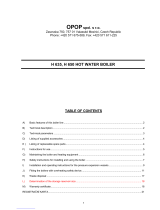
2.2 BOILER SCHEMATICS
KEY:
1. Control AK4000
2. Upper door
3. Chimney flap operating rod
4. Chamber area
5. Primary air conduction
6. Flap for servo Belimo
7. Fan
8. Fan cover
9. Nozzle
10. Secondary air flap
11. Handle
12. Fireclay bricks
13. Bottom door
14. Chimney output
15. Exchanger cover
16. Light up flap
17. Upper back panel
18. Water outlet
19. Thermal fuse
20. Thermometer
21. Upper front panel
22. Lambda sonda
23. Gases thermometer
24. Exchanger pipes
25. Heat proof/concrete filling
26. Secondary air
27. Combustion chamber
28. Gases direction
29. Reverse water leak
30. Filling leak
31. Cleaning flap for 29UD
32. Cleaning slot for 29UD
Sche
ma
tic
VIGAS 60,80
Schematic VIGAS 25
Schematic VIGAS 40
Schematic VIGAS 100
Schematic VIGAS 16
Schematic VIGAS 29 UD
Pic. 3
Inlet brand for drain valve
Hole for drown valve insert
Outlet brand of cooling water ¾“
Outlet brand of hot water
Inlet brand of reverse water
Water filling valve

7
Gasifying boiler VIGAS
3. DESCRIPTION OF AK4000 CONTROL
3.1 SAFETY INSTRUCTIONS
Please check the protective cover panels before you plug-in the power lead
Avoid any contact of the power lead with hot parts of the boiler (e.g. smoke flue).
Make sure that upper insulation under the panel remains dry (risk of short circuit if damp)
Do not put any stress on power lead.
Always disconnect the power lead when new electrical components are being connected to the
boiler (eg indoor room thermostat, discharge fan, circulation pump...)
Do not remove the protective cover panels, and particularly the fan cover panel, when the boiler is
in operation.
Check if the voltage displayed on the label is same as your distribution network.
Always keep to the terms of use
3.2 CONNECTION TO THE POWER SUPPLY
AK 4000 Control is an integral part of VIGAS boilers.
The control is connected when the power lead is plugged into a 220/230V power supply. The visual display
with basic image is active when the power lead is plugged-in (pic.4). Servo-flap used in VIGAS
Lambda Control
is set to basic position (pic.5).
3.3 SERVICE CONDITIONS
AK4000 Control is designed for operation within a temperature range from +5°C up to +45°C. The Control
cannot be used in a moist environment or in direct sunlight.
3.4 MAINTENANCE OF AK4000 CONTROL
Keep in a clean and dust free environment. Anti-static cloths or wet wipes are recommended to wipe-off
dust and impurities from metal covers and the control panel.
3.5 CONTROL PANEL
Part of the electronic control panel is equipped with buttons, visual display and schematics. Further
information is available in the following sections of this manual.
pic.
6
Pic.5
1. Graphic display 128 x 64 pix.
2. Button ◄ with functions, ENTER
3. Button▲ with functions
4. Button ► with functions, EXIT (ESC)
5. Button (ENTER) with functions
6. LED control (green - OK, red - ERROR)
7. Button switch functions
Pic.4
pic.
7
Graphic information
Coding line information
(chap.13.5)

8
Gasifying boiler Vigas
3.6 SYMBOLICS
1. Real time indication
2. Coding line –
indication of current boiler figures
Modification ▲ or
3.
Indication of discharge fan, lambda sensor, gas
thermometer
4.
Indication of nominal output when boiler is
switched off.
Boiler
Accumulator
tank
External boiler
Boiler „ON“ ON DUOMIX Heating Circuit
Boiler „OFF“ OFF Valve with
servomotor
Indoor
thermostat
Flame up
ON Pump
3-way
thermostatic
valve
Burning
73
0
C Discharge fan LADOMAT
Afterflaming
52
0
C Lambda
λ
Fan
End of burning
END Thermometer
T
Fan change
output
External
thermometer
Floor heating
Boiler
attenuation Indication figure
error
x
Servo-flap
position
servo 50%
Add fuel Shut-down
temperature end Max. exhaust
gas figures max
Temperature
set up
Parameters
set up
Time set up
Error
notifications
Programm
Configuration
data
Servise set ups
Memory modul
Motion
regulation
Schemas
option Installation data
Indication
option
5.
Graphic indication of hydraulic connection
schematic.
6. Boiler status indication
7.
Battery condition (2 units type AA) used
to
close servo-flap (only VIGAS
Lambda Control
)
8. Symbols
9. Set figures
10. Current figures

9
Gasifying boiler VIGAS
4. BASIC CONFIGURATION OF VIGAS BOILER WITHOUT
EXHAUST FAN
The advantage of the exhaust gas thermometer is to control the maximum exhaust gas temperature, and when this is
reached by the boiler, a fan will come into operation to lower the engine RPM. This results in higher boiler efficiency
and lower fuel consumption. If installed with an accumulator tank, the thermometer will shut down the boiler when fuel
is burned down. The water temperature inside the boiler and accumulator tank has no influence on boiler shut down.
4.1 VIGAS BOILER CONTROL
4.1.1 Boiler activation
4.1.2 Boiler active – heating phase, heating regime „On“
4.1.3 Boiler active – burning phase „74°C“
4.1.4 To add fuel or boiler shut-down (manual control)
By pressing „ “ fan will be switched off. Use lever t
o open chimney flap
and consequently open the upper door. Fuel can be added if necessary.
After reloading close the upper door and
chimney flap (pic.12.4).
By
pressing „ “ refuelling will be ended. Fan will switch on automatically.
In the heating phase, the boiler gas exhaust temperature is lower then
the
minimum set-up exhaust gas temperature
. Minimum and maximum
temperatures can be modified in boiler set-
up parameters. Minimum
standard exhaust gas set-up temperature is up 90°C and maximum set
-
up temperature is 220°C.
Boiler can be in heating mode for up to 60
minutes with minimum of 2min. If boiler does not reach bu
rning phase in
this time, it will automatically shut down – sign „END“.
OFF will be displayed when the boiler is switched off. To START the
boiler press middle button ENTER.
The burning phase is active, when the exhaust gas temperature is
(
end) +10 °C or after reaching desired temp. Burning phase is
controlled by PID regulator on the basis of chimney and boiler temp.
If the
temperature rises 1°C above desired temp., the output will be 0
%. If it
decreases >2°C below desired temp., the output will start again.
Choose one option
OFF Switch off
Add boiler
⌧
Cancel display driver
▲
Change indicated figure
Graphic control is used for this operation.
To activate display driver press
middle button „ENTER“. Graphic control offers option to: switch-
off boiler,
add fuel or cancel display driver.

10
Gasifying boiler Vigas
Choose one option
+60 To start discharge fan for 60 secs (use with open burn phase)
ON
Switch on
⌧
Cancel display driver
▲
Change indicated figure
Select „+60“ new graphic drive will appear. Running time of discharge
fan is located in the left upper corner of the display.
+60
You can add an extra 60 secs – to a maximum 300 secs
ON
Switch on
0
Discharge fan switched-off
▲
Change indicated figure
4.1.5 Boiler shut-down (automatic)
5. VIGAS BOILER CONFIGURED WITH DISCHARGE FAN
(without lambda sensor)
The advantage of a discharge fan installation is increased comfort during boiler open burn and refuelling
stages. The discharge fan helps to significantly reduce flue gas and smoke escape in the surrounding area
during the refuelling stage. The discharge fan helps to quickly start the fire.
5.1 VIGAS BOILER CONTROL
5.1.1 Boiler activation
5.1.2 Boiler active – heating phase „ON“
5.1.3 Boiler active – burning phase „82°C“
When exhaust gas temperature drops under the set-up temperature (
end), the boiler is automatically switched-off. Sign „END“
will be indicated
on the display. By pressing the „ENTER“ button twice the boiler will start
-
up again.
If the boiler is in shut-down phase, with symbo
l „OFF“ on the display, to
start-up press middle „ENTER button.
In the heating phase, the boiler gas exhaust temperature is lower then
the
minimum set-up exhaust gas temperature
. Minimum and maximum
temperatures can be modified in boiler set-
up parameters. Minimum
standard exhaust gas set-up temperature is up 90°C and maximum set-
up
temperature is 220°C.
Boiler can be in heating mode for up to 60 minutes
with minimum of 2min. If boiler does not reach burning phase in this time,
it will automatically shut down – sign „END“.
The burning phase is active, when the exhaust gas temperature is
( end)
+10 °C or after reaching desired temp. Burning phase is
controlled by PID regulator on the basis of chimney and boiler temp.
If the
temperature rises 1°C above desired temp., the output will be 0
%. If it
decreases >2°C below desired temp., the output will start again.

11
Gasifying boiler VIGAS
5.1.4 Add fuel, boiler shut-down (manual control)
5.1.5 Boiler shut-down (automatic)
6. BOILER VIGAS
Lambda Control
IN BASIC CONFIGURATION
WITHOUT EXHAUST FAN
Boiler VIGAS
Lambda Control
operates using information about the oxygen in the exhaust gas received from
lambda sensor to control the flap of primary and secondary air. This system allows burning of all types of
wood more efficiently and at the same time decrease the fuel consumption by 20-25 %.
6.1 VIGAS
Lambda Control
BOILER CONTROL
6.1.1 Boiler activation
Choose one option
OFF Switch off
Add fuel
⌧
Cancel display driver
▲
Change indicated figure
By pressing „ “ , the boiler fan will be switched-
off and the discharge fan will
be switched-on between 60 secs and maximum 300 secs.
The time is indicated
in the upper left hand corner of the display. By pressing button „+60“
it is
possible to extend discharge fan running time.
Using the lever, open chimney
flap and consequently open the upper door. You can add fuel if
necessary.
After fuel reloading close the upper door and
chimney flap (pic.12.4).
By
pressing
„0“
the discharge fan will be switched off, boiler fan will start working
automatically.
When exhaust gas temperature drops under the set-up temperature (
end), the boiler is automatically switched-off. Sign „END“ will be indicated
on the display. By pressing the „ENTER“ button twice, the boiler will start
operating again.
The graphic control is used for this operation.
To activate display driver
press middle „ENTER“ button. The graphic control offers option to:
switch-off boiler, add fuel or cancel display driver.
If the boiler is in shut-down phase, with symbol „OFF“ on
the display, to
start-up press middle „ENTER“ button.

12
Gasifying boiler Vigas
The servo-controlled flap will move to open
position (servo 100%) when
„ENTER“ button is pressed. Consequently, the following sequence
100%
down to 45% will move the flap to retain the lambda sensor value of
λ
1,35.
When displaying servo at 45%, secondary air is closed. When
displaying 0% primary a
ir is also closed. The flap will move to position
0% only when boiler is in the „OFF“ or „END“ phase.
In the heating phase, the boiler gas exhaust temperature is lower then
the
minimum set-up exhaust gas temperature
. Minimum and maximum
temperatures can be modified in boiler set-
up parameters. Minimum
standard exhaust gas set-up temperature is up 90°C and maximum set
-
up temperature is 220°C.
Boiler can be in heating mode for up to 60
minutes with minimum of 2min. If boiler does not reach burning phase in
this time, it will automatically shut down – sign „END“.
.
6.1.2 Boiler active – heating phase „On“
6.1.3 Boiler active – burning phase
6.1.4 Add fuel, boiler shut-down (manual control)
6.1.5. Boiler shut-down (automatic)
The burning phase is active, when the exhaust gas temperature is
(
end) +10 °C or after reaching desired temp. Burning phase is
controlled by PID regulator on the basis of chimney and boiler temp.
If the
temperature rises 1°C above desired temp., the output will be 0
%. If it
decreases >2°C below desired temp., the output will start again.
Choose one option
OFF Switch off
Add fuel
⌧
Cancel display driver
▲
Change indicated figure
By pressing „ “ the boiler fan is switched off.
Open chimney flap
and
upper door. Add fuel as necessary. After that, close upper door and
chimney flap. By pressing „ “
finishes fuel reloading and the fan will be
switched on. During fuel reloading, the servo-
controlled flap remains in
the same positi
on as it was before adding fuel. When fuel reloading is
complete, the flap moves to the position (servo 100%).
Consequently,
the following sequence 100% down to 45%
will move the flap to retain the
lambda sensor value of λ 1,35. When displaying servo at 4
5%, secondary
air is closed. When displaying 0% primary air is also closed. The flap will
move to position 0% only when boiler is in the „OFF“ or „END“ phase.
When exhaust gas temperature drops under the set-up temperature
( end), the boiler is automatically switched-off. Sign „END“
will be
indicated on the display. By pressing the ENTER“ button twice, the boiler
will start operating again.
The visual graphic control is used for this operation.
To activate the
display driver, press small middle bu
tton ENTER. The graphic control
offers options: switch-off boiler, add fuel or cancel display driver.
.

13
Gasifying boiler VIGAS
Choose one option
+60 Start-up discharge fan for 60 secs (recommended in the
heating phase)
ON
Switch on
⌧
Cancel display driver
Change indicated figure
Select „+60“ a new graphic drive will be displayed. Running time of
discharge fan is located in the left upper hand corner of the display.
+60
You can add an extra 60 secs to a maximum of 300 secs
ON
Switch on
0
Discharge fan turns-off
▲
Change indicated figure
7. VIGAS
Lambda Control
BOILER CONFIGURED WITH THE
DISCHARGE FAN:
The VIGAS boiler
Lambda Control
operates with information about oxygen overflow in exhaust gas received from
the lambda sensor which controls the flap of primary and secondary air. This system allows buring of all
types of wood more efficiently and at the same time reduces fuel consumption by 20-25 %.
7.1 VIGAS
Lambda Control
BOILER CONTROL:
7.1.1 Boiler activation
7.1.2 Boiler activated – heating phase „ON“
7.1.3 Boiler activated – burning phase „79°C“
7.1.4 Add fuel, boiler shut-down (manual control)
If the boiler is switched-off with symbol „OFF“ on the display, to re-
start,
press the middle button „ENTER“.
By pressing „ON“ button the servo-
controlled flap will move to an open
position (servo 100 %). Consequently, the following sequence
100%
down to 45% will move the flap to retain the lambda sensor value of λ
1,35. When displa
ying servo at 45%, secondary air is closed. When
displaying 0% primary air is also closed. The flap will move to position
0% only when boiler is in the „OFF“ or „END“ phase.
In the heating phase boiler gas exhaust temperature is lower then set-
up minimum
exhaust gas temperature. Minimum and maximum
temperatures can be modified in boiler set-
up parameters. Minimum
standard exhaust gas temperature set-up is up to 50°C
and maximum
set-up temperature is 220°C. The pump operates in a continuous
wave during o
pen burn, depending on the boiler water temperature.
The burning phase is active, when the exhaust gas temperature is
(
end) +10 °C or after reaching desired temp. Burning phase is
controlled by PID regulator on the basis of chimney and boiler temp. If
the
temperature rises 1°C above desired temp., the output will be 0
%. If it
decreases >2°C below desired temp., the output will start again.
The graphic control is used for this operation.
To activate the display
driver press the middle button ENTER. G
raphic control gives options:
switch-off boiler, add fuel or cancel display driver.

14
Gasifying boiler Vigas
7.1.5.Boiler shut-down (automatic)
8. TEMPERATURE SET-UP
9. SET-UP PARAMETERS:
Choose one option
OFF Switch off
Add fuel
⌧
Cancel display driver
▲
Change indicated figure
By pressing „ “ the boiler fan will be switched-off and the disch
arge fan
will be switched
-on for 300 secs. The time is indicated in the upp
er left
hand corner of the display. By pressing button „+60“ it
is possible to
extend the discharge fan running time. Using the lever,
open chimney
flap and consequently open the upper door.
You can add fuel if
necessary.
When fuel reloading is complete, close the upper door and chimney
flap.
By pressing „0“ the discharge fan will be switched off. By pressing „
“
fuel reloading is ended and the discharge fan automatically switche
s off
and the boiler fan is switched on. During fuel reloading the servo
-
controlled flap remains in the same position as it was before adding fuel .
When fuel refilling is finished, the flap moves to position
(servo 100%).
Consequently, the following sequence 100% down to 45%
will move the
flap to retain the lambda sensor value of λ 1,35.
When displaying servo at
45%, secondary air is closed. When displaying 0% primary air is also
closed. The flap will move to position 0% only when boiler is in the „OFF“
or „END“ phase.
When exhaust gas temperature drops under the set-up temperature
( end) the boiler is switched off automatically. Symbol „END“
will
appear on the display. The servo-controlled flap will move to position
(
servo 0%). In this position pri
mary and secondary air are closed. By
pressing the „ENTER“ button twice, the boiler will start operating again.
By pressing
„ENTER“
button for 2 seconds temperature set-up can be changed in any phase of the
boiler. In the basic configuration of the boiler (without EXPANDER AK4000), it is only possible to set-up
boiler temperature. Temperature scale is between 70
0
C and 85
0
C.
By pressing
„ENTER“
button for 2 seconds set-up parametres can be changed in any boiler operating
phase
by pressing ▲ button. Set-up p
arametres depend on the type of boiler and its configuration.
By pressing ▲
choose the required parameter and by pressing „ENTER“ symbol starts flashing. By pressing ▲
choose required parameter and confirm by pressing „ENTER“.
2 sec.
2 sec.

15
Gasifying boiler VIGAS
9.1 MAXIMUM EXHAUST GAS TEMPERATURE SET UP
9.2 EXHAUST GAS TEMPERATURE SET-UP
9.3 LAMBDA VALUE SET-UP
9.4 FAN OUTPUT SET-UP
9.5 FAN MINIMUM OUTPUT SET-UP
9.6 MINIMUM TEMPERATURE IN THE ACCUMULATION TANK SET-UP
9.7 DISCHARGE FAN SPEED SETTING
max
Select maximum exhaust gas temperature, which will result
in reducing fan speed. It is possible to set-up temperature
between 130°C and 320°C. Temperature set-up depends
on quality of fuel and chimney draught. Recommended
value is 220°C.
end
You can set up exhaust gas temperature to automatically
shut down boiler and pump. It is possible to set-up this
temperature between 20°C and 130°C. If the temperature is
too low, the fuel will burn compeletely. If the temperature is
too high, there will be too much ash in ash in exchanger.
By selecting the temperature, it is possible to control the
size of fire base for the next heating phase.
By increasing or decreasing the value can change the
nominal boiler output. It is possible to change the value
from -3 to +3. One degree represents about 10% of boiler
output. During warmer weather it is advised to decrease
this value.
min
Increasing the value will change the minimum fan speed.
Value can be selected between 0% and 70%. After
reaching the selected set-up value the fan will switch off.
on
In case, the boiler is equipped with discharge fan (see
chap.13.1.3), it can be used in permanent mode to increase
chimney effectiveness. It is possible to control speed
between 30% and 100% or complete shut down by „OFF“
symbol. If it is set as percentage, the fan works together
with blower fan.
λ
Lambda value specifies oxygen surplus in the exhaust gas.
Recommended value is 1.35, which is about 6% of O
2
. It is
possible to set-up this value from 1,2 up to 1,5. By
increasing the value of O
2
in the exhaust gas, the boiler and
emmissions will be less efficient.
MinT
Setting the minimum temperature in the accumulation
tank. Setting range 25-
70°C. If the selected hydraulic
diagram of the accu.tank (see 13.4) and the boiler
exceeds the desired tempe
rature by 1 ° C. of the boiler
there is a transition to a state of depression
The
re-
heating up of the boiler starts when the temperature
in the accu.tank drops to a preset value eg. 30°C.

16
Gasifying boiler Vigas
9.8 DISPLAY INTENSITY SET-UP
9.9 DISPLAY CONTRAST SET-UP
9.10 SCROLLING MENU SET-UP
10. TIME SET-UP
11. HARDWARE AND SOFTWARE INFORMATION
12. ERROR NOTIFICATIONS
By pressing „ENTER“ button, values start flashing. Pressing ▲
choose correct time and date. Mon – Monday, Tue – Tuesday, Wed –
Wednesday, Thu – Thursday, Fri – Friday, Sat – Saturday, Sun –
Sunday.
Warning : During an electricity power-cut clock will stop.
To retrieve information setting, press and hold „ENTER“ button at any boiler phase and press button
. Confirm by
pressing „ENTER“. Use buttons ▲
to choose module and confirm by pressing „ENTER“. Information about the
module will be indicated on the display.
AK4000D – Display, AK4000S – Power board unit, AK4000L –
Lambda board module.
To recall error notification press and hold „ENTER“ button at any boiler phase and press
button
twice
. By pressing „ENTER“, error with description will be indicated on the display.
Choose display intensity value. Select value between
0 and 100.
Choose display contrast value. Select value between
18 and 34.
Roll
By choosing „
yes“
option on the display (pic.7) will
show actual boiler values - for example: fan speed,
boiler temperature, exhaust gas temperature, etc. By
choosing „no“ option, selection can be made using
buttons ▲
.
Set-up time and date when the boiler is first plugged in. Time is indicated in the upper left hand corner of
the display. To retrieve parametre settings press and hold „ENTER“ at any boiler phase and then press
▲ button twice.
2 sec.
2 sec.
2 sec.

17
Gasifying boiler VIGAS
STB
12.1 STB failure
13. SERVICE SETTINGS PIN 0000 PROTECTED
13.1 SERVICE SETTINGS
13.1.1 Boiler type setting
13.1.2 Lambda sensor setting
13.1.3 Exhaust gas thermometer settings
Service settings are passworded. Only a trained service engineer can alter these settings.
PIN 0000
can only be
used to alter settings in unavoidable instances. In service settings, boiler type can be selected together with
accessories and hydraulic connection schematic, etc. To select service settings using password „PIN 0000“
press
and hold „ENTER“ button at anytime, press ▲button and then press and hold button ◄ for 4 seconds.
„PIN 0000“
will apear. Press „ENTER“ button 4 times. Service sett
ing symbol will appear on the display. Press „ENTER“
and by
choosing buttons ▲ select service operation.
No errors = Green LED indicator
Errors = Red LED indicator
Error notifications and solutions are described in chapter 18.“
PROBLEMS, CAUSES AND SOLUTIONS“
„STB“ failure is caused by the boiler over-
heating.
When this happens, the thermal fuse is activated (
see
pic.)
and the fan is disconnected from the power supply.
The boiler is only re- activated if „STB“
is reset manually
only when the boiler temperature is below 60°C.
To
switch on the boiler press „ENTER“ button.
ATTENTION!
The control display unit of the boiler AK4000 is used to operate all types of
VIGAS boilers. It is important that the
symbol displayed is the same as the boiler
type. When the boiler is in „OFF“
phase the visual display shows the type of
boiler which is compliant with its nominal output.
For correct boiler operation
the type of the boiler must always be the same as the
type indicated on the
production label. Always check, in case the AK4000 display is replaced!!!
Choose boiler type. Type of boiler must be identical
with boiler type indicated on the production label.
Marked: V25 - boiler output TVZ – hotair boiler, UD –
wood-coal, DP – wood-pellets, L – Lambda control.
λ
It is possible to de-activate the lambda sensor from operation
if an error occurs. If this happens, it is possible to run the
boiler in standard version until the lambda sensor is
replaced.
yes = boiler with lambda sensor, no = boiler without lambda
sensor
In case of exhaust gas thermometer error, it is possible to
disconnect the thermometer. The boiler will operate without
the thermometer until it is replaced. Exhaust gas
thermometer will not be used, when the boiler is de-
activated, use boiler thermometer symbol: yes = boiler with
thermometer, no = boiler without thermometer.
4s
ec
4
x
2 sec.

18
Gasifying boiler Vigas
13.1.4 Discharge fan settings
13.1.5 Boiler thermometer setting
13.1.6 Maximum chimney temperature settings
13.1.7
Minimal temperature setting for boilers with accumulation tank
13.1.8 Frequency power supply set-up
13.1.9 Temperature unit setting
13.1.10 Summer time setting
The discharge fan is an accessory that can be used with
the boiler. After connection to the boiler and in AK4000
control, it is necessary to choose option „yes“.
yes = boiler with discharge fan, no = boiler without
discharge fan.
MaxT
Maximum chimney temperature setting can be selected
between 75°C and 90°C. Highest value is used for boiler
settings with accumulator tank.
Frequency power supply setting is 50 Hz for EU residents
and 60 Hz for USA and Canadian residents. If you are not
aware of power supply frequency, choose AUTO. Incorrect
frequency can cause clock error.
Temper
.
unit
For temperature unit setting °C-Centigrade or F-
Fahrenheit can be selected.
Summer
Allows set-up to automatically change the clock to
summer-time.
T
There is a possibility to set two types of boiler
thermometers
1. Standard: Type KTY
2.
Alternate: Type PT 1000
MinT
Setting the minimum temperature in the accumulation
tank. Setting range 25-70°C. If the selected hydraulic
diagram of the accu.tank (see 13.4) and the boiler
exceeds the desired temperature by 1 ° C. of the boiler
there is a transition to a state of depression The re-
heating up of the boiler starts when the temperature in the
accu.tank drops to a preset value eg. 40°C.

19
Gasifying boiler VIGAS
13.2 MODULE AK 4000M SETTINGS
13.3 SERVICE CONTROL FUNCTIONS
13.4 HYDRAULIC SCHEME BOILER SETTING
13.4.1 BASIC CONNECTION SCHEMES
config
To load a new configuration (connection schematic).
Mainly used for systems controlled by EXPANDER AK4000E,
where it is possible to load personal connection schematics.
config Actual configuration back-
up. It is used for boiler monitoring. It is
advised to perform before monitoring.
firmware To load firmware (boiler operating software).
Erase To delete information from module AK4000M.
mon Boiler monitoring -
to file basic information of the boiler into
memory module.
AK4000S To load firmware into the power board AK4000S.
AK4000L To load firmware into the lambda power board AK4000.
By changing hydraulic scheme connection will also change the control of the pump o
utput and boiler configuration.
Therefore, it is very important that software settings for the hydraulic schematic is identical with existing boiler
installation in the central heating system. In the basic memory of the control unit are 4 basic schemes and
schemes
intended for operating with the Expander AK4000E.
On demand, it is possible to add Expander schemes via
AK4000M module (pic.8). Updated schemes for Expander AK4000E can be found on www.vigas.eu
obr.
8
When necessary, it is possible to connect AK4000 control to module AK4000M (pic.8). This module allows the
provision of upgrades and back-
up data maintenance of the boiler control unit. The module is equipped with data
to make it possible to connect to BH BUS power board.
In service settings the functions of each boiler‘s components can be checked according to the symbols in
dicated on
the display. By selecting component and
pressing „ENTER“ button the function will be activated. Displayed
components depend on the boiler‘s configuration.
Using ▲
buttons
,
choose required scheme
and press „ENTER“.
Schema 1 for (BS
-
3)
shall be used with accumulator tank. To protect from low-
temperature corosion, a three-
way thermostatic valve ESBE is used (60°C). Pump
shall be connected to power board AK4000.
Contact T3 of power board AK4000S
is used to connect KTY sensor, to monitor tank temperature.
Attention:
It is not possible to connect room thermostat with Schema 1. I tis
recommended to control the room thermostat by pump.
Schema 0 for (basic schema/BS
-
1)
to protect from low-temperature corosion,
a three-way thermostatic valve ESBE is used (60°C). Water regulation for central
heating is secured by 4-way mixing valve with manual control. For boiler heating,
a combined tank is used. Both pumps must be connected to power board
AK4000. Contact T3 of power board AK4000S is used for connection of room
thermostat (see 20/B2 and 16.4.)
2x
3x

20
Gasifying boiler Vigas
13.4.2 CONNECTION SCHEMES WITH EXPANDER AK4000E
Schema 4
is designed for manual control with 4-way valve. For boiler heating,
a combined tank is used. Both pumps must be connected to power board
AK4000. Contact T3 of power board AK4000S is used for connection of room
thermostat (see 20/B2 and 16.4.)
Recommendation: Connection without 3-
way thermostatic valve does not
secure sufficiently water temperature to 60°C. In order to expand the
lifespan of boilers, it is recommended to use Scheme 0.
Schema 2 for
(BS
-
2
)
Scheme is the same as scheme 0.
To control water
temperature for central heating, the 3-way mixing valve is us
ed, which is operated
manually.
Attention: Combines water tank must be used together with 3-
way mixing
valve.
Schema 3
to protect from low-temperature corosion, a three-way thermostatic
valve ESBE is used (60°C). Pump must be connected to power board AK4000.
Contact T3 of power board AK4000S is used for connection of room thermostat
(see 20/B2 and 16.4.)
Schema 5
used with one heating circuit for floor or radiator. Central heating
temperature can be controlled according to external temperature, room
thermostat or by combi
nation of both. The boiler pump and central heating pump
are controlled separately. Boiler protection against low-
temperature corrosion
provides 4-way valve with servounit.
Use: Expander basic set (code 5001).
Schema 6
with two separate heating circuits controlled by servounit.
Option to
choose floor or radiator heating or combination. Central heating temperature can
be controlled according to external temperature, room thermostat or with
combination of both. The boiler pump and central heating pump work
separately.
Boiler protection against low-temperature corrosion provides 3-
way thermostatic
valve (60°C).
Use: Expander double set (code 5002).
Schema 7 for (Basic scheme expander (BSE 1)
used with one heating circuit
controlled by servounit for floor o
r radiator heating. Heating of domestic water
supply is controlled by pump. Temperature of central heating is controlled by
external temperature, room thermostat or by combination of both. Boiler
protection against low-temperature corrosion provides 4-way mixing valve.
Use: Expander basic set (code 5001)
Expander AK4000E complements the AK4000 boiler control unit. It enables the possibility to control
the central
heating system unit circuits, including regulating the supply water temperature, using different heating sources.
Use
of indoor thermostat and equithermic control (based on external temperature) or in combination, enables control of the
central heating. Expander AK4000E is supplied in sets. According to the particular schematic connection, it i
s
supplied as: basic set (order no. 5001), double set (order no. 5002) and triple set (order no. 5003)
. After verifying the
connection schemes of the Expander, service settings will be supplied with unit settings for the central heating system
and hot water supply. (Detailed description given in EXPANDER AK4000E service guide).
Technical requirements for additional accessories:
(To specify type, pump diameter and servo-unit consult with boiler specialist)!
1.
Pump 230V/50 Hz.
2.
Servo-unit 230V/50 Hz opening period 60–240 secs
3.
Pump to be installed circa 0,5 m after 4-way valve.
4.
Maximum electrical current for one EXPANDER is 3Amps.
5.
Additional thermometer to be installed circa 0,5 m after pump.
6.
External thermometer to be installed on the nothern side of building
7.
Indoor thermostat - free of voltage.
Expander Basic set (order no. 5001)
/