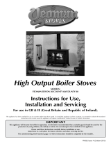
Lorraine MF 124 13 01

FRANCO BELGE Lorraine MF 124 13 01 Technical Manual

  • Hello! I am an AI chatbot trained to assist you with the FRANCO BELGE Lorraine MF 124 13 01 Technical Manual. I’ve already reviewed the document and can help you find the information you need or explain it in simple terms. Just ask your questions, and providing more details will help me assist you more effectively!
  • What is the maximum heat output of the FRANCO BELGE Lorraine MF 124 13 01?
    What is the weight of the FRANCO BELGE Lorraine MF 124 13 01?
    What is the principle of operation of the FRANCO BELGE Lorraine MF 124 13 01?
    What is the recommended chimney height for the FRANCO BELGE Lorraine MF 124 13 01?
    What is the maximum length of the connecting flue for the FRANCO BELGE Lorraine MF 124 13 01?
    What type of flue pipe is required to connect the FRANCO BELGE Lorraine MF 124 13 01 to the chimney?
Description of the appliance
Installation instructions
Operating instructions
Spare parts
Warranty certificate
Document n° 316-6 ~ 28/01/2004
STAUB FONDERIE
Head Office Address
2, rue Saint Gilles
68230 TURCKHEIM
RC Colmar
SIREN 439 330 325
Address - Administration and
manufacturing
BP 73
59660 MERVILLE (FRANCE)
Telephone : 00 333 28 43 43 43
Fax : 00 333 28 43 43 99
Subject to modifications.
Lorraine MF
Multifuel stove
Model : 124 13 01 Technical manual
to be saved
by the user
for future reference
EN FR PL ES PL
2Notice de référence “316”
Lorraine MF/Alsacien - réf. 124 13 01
Contents
Description of the unit .....................................3
Package ...................3
General characteristics...........3
Descriptif . . . . . . . . . . . . . . . . . . 3
Principle of operation . . . . . . . . . . . . 3
Installation instructions ....................................4
Assembly of the flue collar and the blanking
plates ....................4
Installation..................4
Siting the stove ...............4
The chimney ................5
Chimney connexion. . . . . . . . . . . . . 5
Water connections . . . . . . . . . . . . . 5
Check list before lighting stove . . . . . . 5
Adjustment of the thermostat .......5
Instructions for user ......................................6
Fuel .....................6
Lighting the stove ..............6
Running the stove .............7
Maintenance ................7
Care of the stove ..............7
Cleaning the glass . . . . . . . . . . . . . 7
Flue cleaning and summer time . . . . . . 7
Removing the oscillating grates . . . . . . 7
Trouble Shooting ..............8
List of components.......................................9
1. Description of the unit
1.1. Package
-1 package : Stove complete.
-Optional : add-in boiler C 22 30 01 or C 22 07 01
1.2. General characteristics
Reference ............... 1241301
Maximum heat output .......kW 12,2
Weight................Kg 150
Fire box dimensions
- width ...............mm 460
- depth...............mm 260
- useful height...........mm 180
ashpan capacity .........litres 6
overnight solid fuel loading ....Kg 8
1.3. Descriptif
Multifuel stove.
Fuel burnt on grate.
Enclosed combustion chamber with refractory brick
walls.
De-ashing and ash-dumping devices.
Large ash-pan.
Adjustable air controls with thermostat.
Detachable flue spigot for rear or top chimney
connection.
Boiler with water connections (optional).
1.4. Principle of operation
The “ Lorraine MF ” is designed for operation with the
door closed.
Heat is mainly diffused by radiation, through the window
and body of the appliance.
Adjustable air controls with thermostat for controlling
the burning rate.
Combustion occurs on the grates in a hot enclosed
combustion chamber. The thermostat regulates the
draught entry under the grates.
Notice de référence “316” 3
Lorraine MF/Alsacien - réf. 124 13 01 Description of the unit
WARNING
The appliance must be installed in compliance with Current Building Regulations.
Incorrectly installed, this appliance can be dangerous
and possibly cause serious accidents.
The manufacturer’s responsibility shall be limited to the supply of the equipment.
Figure 2 - Dimensions in mm
2 different diameters for flue outlet, depending on the flue
collar used ; 153 mm i.d. or 139 mm o.d.
Stove with add-in boiler
2. Installation instructions
2.1. Assembly of the flue collar and the
blanking plates
The flue collar and the 2 blanking plates are assembling
deliver on the stove for smoke exit at rear.
Smoke exit at rear (fig. 3) :
The blanking plates are fitted on the top plate from
factory, fit the flue collar (3 bolts) with fire ciment.
Lift the top plate (2 bolts) and remove the rear heat
shield.
For installation smoke exit on the top (fig. 4):
Lift the top plate (2 bolts) and remove the rear heat
shield.
Remove the flue baffle and the refractory bricks
(#25,#4and#5p.11).
Exchange the blanking plates with the flue collar,
ensuring that it is leaktight.
Replace the refractory bricks and the flue baffle.
Reinstall the rear covering and closed the exit position
with an iron plate.
Refit the top plate.
2.2. Installation
Important : Before commencing the installation of your
new appliance it is recommended that the instructions
are read and understood.
Health and safety at work act 1974 :
The installer should comply with the Health and Safety
at Work Act 1974 and with particular reference to the
following.
Handling :
Adequate facilities should be provided for handling the
appliance.
Glass :
Extra care should be taken to avoid breakages.
Fire cement :
Care should be taken to avoid fire cement contacting
the skin. The material is caustic and in the event of
contact being made, wash off immediately with clean
water.
Electrical :
If electrical components are to be used in the
installation system, all installation work must be carried
out in accordance with the Regulations for the Electrical
Equipment of Buildings. Care should be taken to
conform to the installation instructions of individual
manufacturers.
Flues, combustion air supply and connection of the
appliance
Current Building Regulations and relevant Codes of
Practice must be observed.
The responsability of FRANCO-BELGE only affect the
supply of the appliance.
2.3. Siting the stove
The hearth on which the stove is to be installed must
comply with Current Building Regulations.
A fresh air inlet must be provided in order to allow
efficient combustion and to avoid a vacuum effect being
created in the room ; air extractors and fans must not be
used in the same room or adjoining room to the
installation.
This stove is not designed to be built in, and an air
space of at least 150 mm must be left all around the
stove. Ensure that appliance and flue pipe are clear of
combustible materials.
The stove should be level. Sufficient access for
chimney sweeping and appliance cleaning must be
provided.
4Notice de référence “316”
Lorraine MF/Alsacien - réf. 124 13 01 Installation instructions
Figure 3 - Rear flue outlet
Airtight seal
Fire ciment
Figure 4 - Top flue outlet
Airtight seal
2.4. The chimney
The chimney must be in good condition free from cracks
and blockages and should not have an excessive cross
sectional area. If problems are encountered expert
advice should be sought regarding the necessity of
having the chimney lined. Should it be found necessary
to line the chimney, a lining suitable for solid fuel must
be used. If the appliance is to be fitted in a room where
there is no existing chimney a prefabricated block
chimney or a twin walled insulated stainless steel flue to
B.S 4543 can be used either internally or externally. The
internal diameter must not be less than 150 mm (6
inches). These flues must be fitted in accordance with
the manufacturers instructions and Building
regulations.
Before connecting the appliance to an existing flue, the
flue must be swept and checked. In order for the
appliance to perform satisfactorily the chimney height
should not be less than 5 metres measured vertically
from the outlet of the stove to the top of the flue terminal.
Should there be excessive draught in the chimney it
may be necessary to fit a draught stabliliser.
2.5. Chimney connection
No combustible materials may be set closer than at
least 450 mm clearance.
A 150 mm diameter flue pipe will be required to connect
the stove to the chimney. Make sure the flue pipe is
suitable for solid fuel (cast iron, stainless steel, vitreous
enamelled steel). Under no circumstances should
flexible or asbestos pipe be used.
Too long horizontal smoke pipe may dangerously
restrain the running of the appliance (do not exceed 0,3
m in length). The connecting flue should not exceed 1,8
m in length. Greater lengths should be completed by
using twin-walled insulated chimney.
Ensure the flue pipe extends into the chimney but not so
far that it blocks air flow.
Ceiling or wall penetration should always be made with
insulated pipe and the proper accessories.
Allow fire cement to dry properly before lighting the
stove. Stove running and chimney being hot, check if
chimney draught is at least 10 Pa (1 mm w.g.) at normal
rate and 15 Pa (1,5 mm w.g.) at maximum rate.
If chimney draught is too excessive, a flue stabiliser
should be installed on the flue pipe or on masonry
chimney so as to avoid the introduction of cold air into
the chimney.
2.6. Water connections
With add-in boiler C 22.03.01 or C 22.07.01
FRANCO-BELGE recommends that the installation is
carried out by a qualified heating engineer who is fully
experienced in solid fuel heating installations.
Must be provided (fig. 5) :
-an expansion tank open to the atmosphere,
-an indirect cylinder,
-a gravity circulation to one radiator to dissipate heat
when the pump is off,
-the fitting of a low limit thermostat to the primary return
to ensure the pump does not operate when return
water temperatures are less than 50 ° C,
-a drainage tap in the return flow.
2.7. Check list before lighting stove
-check that all firebox parts (grates, flue baffle and
refractory bricks) are correctly fitted and that the
oscillating grates move correctly when operated
-check the appliance for soundness of seals between
casting (flue collar, blanking plates, loading doors,
etc...)
-check the connection between the appliance and the
chimney flue for air tightness
-check if there is enough water in the heating system
and check the connections for water leaks
-after lighting up the stove, check if it operates correctly
under fire, check for soundness of seals, leave the
appliance operational with the heating system
correctly balanced, hand over user instructions.
2.8. Adjustment of the thermostat
The thermostat has been set in the factory. If it becomes
necessary to make adjustments or fit a new thermostat,
the following procedure should be followed (see fig. 6) :
-ensure the appliance is cold,
-remove the rear metal heat shield,
-set the thermostat adjustment lever at position «8»
(fully open),
-adjust the position of the screw on the lever arm to
provide a gap of 50 mm,
-set the thermostat adjustment lever at position «1»
(fully closed),
-refit the rear metal heat shield.
Notice de référence “316” 5
Lorraine MF/Alsacien - réf. 124 13 01 Installation instructions
Figure 5 - Water connections
Figure 6 - Adjustment of the thermostat
Lever arm
Screw
Damper
3. Instructions for user
Warning : properly installed and operated this
appliance will not emit fumes into the dwelling.
Occasional fumes from de-ashing and re-fueling
may occur. Persistant fume emission is dangerous
and must not be tolerated. If fume emission does
persist :
-open doors and windows to ventilate room,
-let the fire out and dispose of fuel from the appliance,
-check for flue or chimney blockage, and clean if
required,
-do not attempt to relight the fire until the cause of the
fume emission has been identified and corrected. If
necessary seek expert advice.
Note : It is recommended to use a fireguard in the
presence of children, and also in the presence of old
and/or infirm people
3.1. Fuel
Recommended fuel :
Coal
Sunbrite (small) - Anthracite (Medium) - Dry Wood
Wood
-Use hard wood logs which have been cut for at least
two years and stored under shelter.
-Hardwood has a higher calorific value per cu metre
(oak, ash, maple, birch, elm, beech, etc.).
-Large logs must be split and cut to the usable length,
before being stored in a sheltered and ventilated
place.
Not recommended as fuel :
-“green wood”. Green or damp wood reduces stove
efficiency and makes the window, the internal walls
and the flue dirty (soot, tar, etc.).
-“used timbers”. Burning treated wood (railway
sleepers, telegraph poles, offcuts of plywood or chip
board, pallets, etc.) quickly clogs the flue ways (soot,
tar, etc.), pollutes the environment (pollution and
smell, etc.) and cause the fire to burn too quickly and
overheat.
“Green wood” and “recovered wood” can eventually
cause a chimney fire.
Prohibited fuel : Any form of bituminous coal or
petroleum based coke.
3.2. Lighting the stove
-Ensure that there is enough water in the heating
system (with add-in boiler).
-Do not light the fire if it is suspected that any part of the
water system is frozen.
-Use crumpled paper or firelighters and enough
kindling wood to obtain a good fire bed.
-Set thermostat control in maximum open position.
-Light the paper through the fuel retainer and close the
loading doors.
-Once the embers are glowing, load the firebox with
solid fuel and close the doors carefully.
-Once the fire is burning well, set the thermostat to
desired position.
-At first lighting, build up heat slowly to allow the
appliance to be correctly “run in”.
Note :
The body of the stove may emit some fumes and give off
a new paint smell for the first couple of hours. This is
quite normal and you shouldn’t worry about it. Make
sure the room is well ventilated during initial use.
6Notice de référence “316”
Lorraine MF/Alsacien - réf. 124 13 01 Instructions for user
Figure 7 - Operating devices
1
2
34
5
6
7
8
close open
open
close
1: Tool for riddling and operate the
loading door.
2: To open the loading door.
3: Safety device (prevents stove
doors from closing if ash pan
door is not fully closed).
4: To open ashpan door.
5: Tool for handling ashpan, for
ash-dumping and for operating
throat plate.
6: Thermostat control.
7: Ash-dumping.
8: De-ashing.
3.3. Running the stove
Rate of burning is obtained by setting the thermostat
control.
Experience will show you which settings are best for
your situation. In general, the higher position is only
required for lighting and restoring the fire.
Overnight burning :
Riddle and de-ash ; run on high setting the stove for
about 15 - 20 minutes : once the embers are glowing
well, stoke up the fire ; half close the thermostat control
for about 15 - 20 minutes before finally setting the
thermostat control for the night at low position.
De-ashing (fig. 8) :
Riddle and de-ash before refuelling and every time
grates become congested. Keep fire bed and air inlet
free from ash.
Riddle with vigorous forward and backwards movement
of the riddling tool.
Ash dumping (fig. 9) :
With the casting handle, pull out control, then insert the
wired handle in riddling control and turn downwards.
3.4. Maintenance
3.5. Care of the stove
Do not use abrasive cleaners, use a dry lint-free cloth or
a soft bristle brush.
3.6. Cleaning the glass
Any deposits on the glass should clear when the stove
is fired high. If there is any soot or tar left, first do wait
until the glass is cool, clean with a proprietory stove
glass cleaner.
Do not use abrasives cleaners.
The glass will resist temperature up to 750°C. Do not
replace broken-glass with substitute materials. Consult
your usual FRANCO-BELGE supplier.
3.7. Flue cleaning and summer time
The chimney and the connecting flue pipe must be
swept a least once a year. Also remove any deposits
from the oscillating grates, the firebox surfaces and the
flue collar. Keep the air inlet door free from ashes.
If left unused for long periods (E.g. summer months)
clean the appliance thoroughly, disconnect flue pipe
and block the chimney, leave all air inlets fully open.
3.8. Removing the oscillating grates
Figure 11 :
De-ash and scale (see fig. 9) the grates.
Open the loading door and remove the fuel retainers.
Remove the 3 firebricks. Lift up the left part of the
oscillating grate, push it to the left and when the right
part of the grate is free, tip it up completely. In case of
exchanging old grates by new ones, operate one grate
by one grate to make sure you keep the riddling device
to the right place. After the exchange, check if riddling
can be done easily without jamming.
When replacing grates or firebricks in models with
add-in boiler, the system must be drained down and the
back boiler removed prior to re-fitting the new parts.
Notice de référence “316” 7
Lorraine MF/Alsacien - réf. 124 13 01 Instructions for user
Figure 8 - De-ashing Figure 9 - Ash-dumping
Figure 10 - Description
1
2
3
4
5
6
7
8
3
1: Rear or top flue outlet
2: Flue baffle
3: Firebrick
4: Thermostat
5: Ash-pan door
6: Oscillating grates (3)
7: Fuel retainers (3)
8: Loading door
3.9. Trouble Shooting
Problem Probable causes -Corrective action
Fire difficult to start
Fire goes out
Wood green, too damp or poor
quality -Use the recommended fuel
Logs are too big -To light the fire, use small, very dry twigs. To maintain
the fire, use split logs
Air starvation -Open lower spin wheel and top air control lever
Insufficient draught -Check that the flue is not obstructed, sweep it if
necessary
-Seek advice from a chimney specialist
Fire burns too quickly Too much draught -Ensure that the lower spin wheel is closed
-Partially close the top air control lever
Excessive draw -Install a draught stabiliser. Consult your Dealer
Poor quality wood -Do not continuously burn small wood, sticks, bundles,
carpentry offcuts (plywood, pallets), etc.
Smokes when lighting up Flue duct is cold -Burn paper and kindling wood to increase heat
Room is in decompression -In houses equipped with mechanical ventilation, partly
open a window until the fire is well established
Smokes while burning Draught is insufficient -Consult a chimney specialist.
-Check that the flue is not obstructed, sweep if
necessary
Down draught -Install an anti-down draught cowl. Consult your Dealer.
Room is in decompression -In houses equipped with CMV, an outside air intake
must be installed for the chimney
Low heat output Incorrect Fuels -Use the recommended fuel
8Notice de référence “316”
Lorraine MF/Alsacien - réf. 124 13 01 Instructions for user
Figure 11 - Removing the oscillating grates
1: Firebricks
2: Oscillating grate
3: Riddling device
4: Riddling control
Figure 12 - Stove with boiler
9: Water flow
10 : Water return
11 : Boiler
12 : Draining
1
2
2
3
4
2
3
4
4. List of components
When ordering spare parts, specify the stove type and
serial number, including the colour index (on the
guarentee or identification plate), the name of the part
and the part number.
Example : “Lorraine MF” stove, model 124 13 01 L,
cast top plate 302108-77
Notice de référence “316” 9
Lorraine MF/Alsacien - réf. 124 13 01 List of components
1 100960 Axis..............................01........Y........L........K
2 100961 Axis..............................01........Y........L........K
3 105123 Adh dump knob .......................01........Y........L........K
4 105233 Firebrick ...........................02........Y........L........K
5 105234 Firebrick ...........................01........Y........L........K
6 161025 Brown touch up kits .....................01.................L........
6 161026 Blue touch up kits ......................01..........................K
7 166042 Spring ............................02........Y........L........K
8 179014 Thermostat..........................01........Y........L........K
9 181614 Ceramics rope ...........Ø9,5 ........1,10 m ......Y........L........K
10 181604 Ceramics rope...........10x4........1,00 m ......Y........L........K
11 205335 Back panel..........................01........Y........L........K
12 208407 Heat shield..........................01........Y........L........K
13 262307 Heat shield..........................01........Y........L........K
14 300105 59 Leg ..............................02........Y..................
14 300105 77 Leg ..............................02.................L ........
14 300105 76 Leg ..............................02..........................K
15 300217 59 Leg ..............................02........Y..................
15 300217 77 Leg ..............................02.................L ........
15 300217 76 Leg ..............................02..........................K
16 300462 Base Plate ..........................01........Y........L........K
17 301146 Ash pan door ........................01........Y..................
17 301146 77 Ash pan door ........................01.................L ........
17 301146 76 Ash pan door ........................01..........................K
18 302108 Cast top plate ........................01........Y..................
18 302108 77 Cast top plate ........................01.................L ........
18 302108 76 Cast top plate ........................01..........................K
19 303718 Blanking plate........................01........Y..................
19 303718 77 Blanking plate........................01.................L........
19 303718 76 Blanking plate........................01..........................K
20 303826 59 Flue collar ..........................01........Y..................
20 303826 77 Flue collar ..........................01.................L ........
20 303826 76 Flue collar ..........................01..........................K
20 303827 59 Flue collar ..........................01........Y..................
20 303827 77 Flue collar ..........................01.................L ........
20 303827 76 Flue collar ..........................01..........................K
21 306219 Firebox rear plate ......................01........Y........L........K
22 309834 Front plate..........................01........Y..................
22 309834 77 Front plate..........................01.................L........
22 309834 76 Front plate..........................01..........................K
23 310714 Right plate..........................01........Y..................
23 310714 77 Right plate..........................01.................L........
23 310714 76 Right plate..........................01..........................K
24 310814 Left plate ..........................01........Y..................
24 310814 77 Left plate ..........................01.................L ........
N° Code Description.........Type .......Qty......Y......L......K
Y= 124 13 01 Y - L= 124 13 01 L - K= 124 13 01 K
10 Notice de référence “316”
Lorraine MF/Alsacien - réf. 124 13 01 List of components
24 310814 76 Left plate ..........................01..........................K
25 323211 Flue baffle ..........................01........Y........L........K
26 325304 Closing ............................03........Y........L........K
27 327801 Inner plate..........................01........Y........L........K
28 404301 Riddling rod .........................01........Y........L........K
29 442100 Riddling bar .........................01........Y........L........K
30 624033 Ash pan ...........................01........Y........L........K
31 808001 ED Opening tool.........................01........Y........L........K
32 900914 De-ash latch .........................01........Y........L........K
33 307422 Face grate ..........................01........Y........L........K
34 900915 Lock complete ........................01........Y..................
34 900916 Lock complete ........................01.................L ........
34 900917 Lock complete ........................01..........................K
35 900918 Knob complete........................01........Y..................
35 900919 Knob complete........................01.................L........
35 900920 Knob complete........................01..........................K
36 988733 Right door complete.....................01........Y..................
36 988734 Right door complete.....................01.................L........
36 988735 Right door complete.....................01..........................K
37 988736 Left door complete .....................01........Y..................
37 988737 Left door complete .....................01.................L........
37 988738 Left door complete .....................01..........................K
38 303508 Right door ..........................01........Y..................
38 303508 77 Right door ..........................01.................L ........
38 303508 76 Right door ..........................01..........................K
39 309944 Left door ...........................01........Y..................
39 309944 77 Left door ...........................01.................L........
39 309944 76 Left door ...........................01..........................K
40 259015 Square ............................08........Y........L........K
41 189105 Screw ..............28x8x7 ........02........Y........L........K
42 181632 Ceramics rope .......................1,72 m ......Y........L........K
43 181602 Ceramics rope .......................1,80 m ......Y........L........K
45 181615 Ceramics rope ...........Ø12.........1,70 m ......Y........L........K
46 188737 Refractory glass .......................02........Y........L........K
48 934801 Oscillating grate with axis .................03........Y........L........K
48 934800 3 oscillating grates ......................-........Y........L........K
51 134751 Pin ................3,5x18.........02........Y........L........K
52 158620 Handle ............................01........Y........L........K
60 911114 Water jacket .........................01........Y........L........K
61 911113 Water jacket .........................01........Y........L........K
62 427002 Seal .............................02........Y........L........K
63 105238 Firebrick ...........................01........Y........L........K
64 122703 Nut ..............................02........Y........L........K
64 122703 Nut ..............................03........Y........L........K
66 110405 Hinge pin .............6x35 .........06........Y........L........K
71 158171 Descriptive plate.......................01........Y........L........K
72 142881 Ceramics rope ........................08........Y........L........K
N° Code Description.........Type .......Qty......Y......L......K
Notice de référence “316” 11
Lorraine MF/Alsacien - réf. 124 13 01 List of components
Conditions of Guarantee
for United Kingdom only
1. The guarantee period is for 12 months
from the date of purchase with the exception
of main body castings which are covered by
the guarantee for a period of 5 years from
the date of purchase.
2. This guarantee is provided as an
additional benefit and does not affect any
other statutory or other rights of the
consumer.
3. The guarantee is only valid in the UK.
4. The appliance must be installed and
operated in accordance with the Installation
and Operators Instructions provided.
5. The guarantee only covers
manufacturing faults. The guarantee does
not apply to consumable items such as
glass, steel or cast iron grates and baffle
plates. The guarantee does not apply to any
damage caused by accident or wear & tear.
6. In the event of a problem, before making
any claim on this guarantee, please ensure
that the appliance has been installed and
commissioned correctly and that the
chimney is operating to the correct draught.
Please refer to your Operators Manual. If
you are unable to resolve the problem,
please report the fault to your dealer quoting
the date of purchase and model reference.
7. Should the product or a product
component be found to be at fault during the
period of this guarantee, the product or
component will either be replaced or
repaired.
8. This guarantee does not cover any
claims for consequential losses or damage.
To register your guarantee, fill in the form below and return to :
ACR Heat Products
P O Box 70
Knowle
Solihull
B93 0ET
United Kingdom
Name ..................................................................................
Address ................................................................................
Postal Code .............................................................................
Telephone (day time)......................................................................
E-mail address...........................................................................
Model Name :
Colour :
Serial Number ...........................................................................
Where purchased ........................................................................
Name of Installer .........................................................................
Address of Installer .......................................................................
q124 13 01
qYqLqK
...............................................................................
§Guarantee certificate §
§Legal guarantee
The specifications, dimensions and information shown on
our documents are provided for information purposes only
and under no circumstances are binding upon the vendor.
With the aim of constantly improving our equipment, all
modifications considered as necessary by our departments
may be made without notice.
The provisions of the present guarantee certificate are not
excluding or limiting the owner of the equipment’s rights,
concerning the legal guarantee regarding faults or hidden
vices which applies in all circumstances, in the conditions
detailed in articles 1641and following of the civil code, and
in the country in which the equipment was purchased.
§Contractual guarantee
Our equipment is guaranteed against faults and hidden
vices subject to the following conditions:
1) Installation and adjustment of the device by a
professional installer.
2) Observance of the instructions provided in our technical
documents and our installation/adjustment instructions.
3) The installation, use and maintenance of the device
carried out in conformity with the applicable standards
and legislation, and with the indications provided in the
technical instructions accompanying the device.
This guarantee covers the replacement, in our factory, of
parts recognised as being defective from the outset by our
“Guarantee Inspection” Department. Carriage and labour
is at the user’s cost. Moreover, if the repair or replacement
of parts covered by the guarantee is found to be too costly
vis-à-vis the price of the appliance, the decision to replace
or repair the appliance will be taken by the vendor.
Our guarantee is for 2 (two) years for all appliances, with
the exception of closed combustion fireplace and inserts for
which our guarantee is 5 (five) years excluding the
following:
1) Indicator lights, fuses, electrical elements and fans.
2) Parts subject to wear or in contact with high
temperatures namely: soles and burner grills, bottom
plates baffles, ash pans, paintwork and surface
treatments for decorative parts. Also excluded from this
guarantee are seals and windows.
3) Any damage which may result from the use of the
appliance with a fuel other than that stipulated in our
instructions.
4) Damage occurring to parts caused by elements outside
the appliance (down draught, storm damage, damp,
abnormal pressure or vacuum, heat shocks, etc.).
5) Damage to electrical parts caused by plugging in and
using the appliance on a mains system, the voltage of
which (measured at the entrance to the appliance) is
10% above or below the nominal voltage of 220 V.
§Exclusion of liability
In the case of a product manufactured at the client’s
request, under no circumstances may we, as a
subcontractor, be considered liable vis-a-vis the client or
third parties for defects arising from the installation or a
design fault with the item in question.
*Name and address of the installer : _____________________________
______________________________________________
(Telephone : _______________________________________
*Name and address of the customer : _____________________________
______________________________________________
Date of installation : __ __ / __ __ /__ __ __ __
Model of the appliance : 124 13 01
Color : YLK
Serial number : ___ ___ ___ ___ ___ ___
• This certificate has to be completed and kept carefully.
In case of claims, send a copy of this to :
STAUB FONDERIE
BP 73, 59660 MERVILLE, FRANCE.
/