Page is loading ...

DROP IN ANCHOR METHOD
C-375/C-450
COMMERCIAL SERIES LIFTS
INSTALLATION MANUAL
Drop In Anchor/COMMERCIAL SERIES
The Drop In Anchor System does not allow for a bond. You can
Bond directly to the lift with the bonding lug provided or some
alternate means. Please contact your local electrical inspector
Before installing any anchoring systems
Feb 2012

Drop In Anchor/COMMERCIAL SERIES
DROP IN ANCHORING METHOD
C-375/C-450
COMMERCIAL SERIES LIFTS
PACKING LIST
• 3 – Drop In Anchor’s
• 3 – 5/8”x 1” Bolts
• 1 – T – Shaped Template
• 3 – Black Caps
• 1 – Bonding Lug w/ nut & bolt
Feb 2012

Drop In Anchor/COMMERCIAL SERIES
ADA GUIDELINES FOR POOL LIFT PLACEMENT
•Pool Lift Location. Pool lifts shall be located where the water level does not exceed 48 inches (1220 mm).
Seat Location. In the raised position, the centerline of the seat shall be located over the deck and 16 inches (405 mm)
minimum from the edge of the pool. The deck surface between the centerline of the seat and the pool edge shall have a
slope not steeper than 1:48.
•Clear Deck Space. On the side of the seat opposite the water, a clear deck space shall be provided parallel with the seat.
The space shall be 36 inches (915 mm) wide minimum and shall extend forward 48 inches (1220 mm) minimum from a line located
12 inches (305 mm) behind the rear edge of the seat. The clear deck space shall have a slope not steeper than 1:48.
•Submerged Depth. The lift shall be designed so that the seat will submerge to a water depth of 18 inches (455 mm) minimum
below the stationary water level.
Feb 2012

Drop In Anchor/COMMERCIAL SERIES
STEP 1: Locate the Drop In anchoring system template (included and shown above)
• Once you determine where your lift is going to be located place the template down
So you can mark on the concrete where you will need to drill the holes.
• The dimensions are as follows: Front of Template must be 12” to 17”
From the water’s edge. Also make sure that the front holes are parallel to the pools edge.
Distance must be 12 to 17””
From water’s edge
Front Holes
Hole’s parallel with water’s edge
***NOTE: The installation of Global Lift Corp’s anchor system’s are a guideline of
minimum requirements. In some states or municipalities they may require
additional steps due to their local codes or ordinances.***
Feb 2012

Drop In Anchor/COMMERCIAL SERIES
Step 2: You will need a 7/8” rock carbide drilling bit.
• Make sure you have accurately marked your hole location to be drilled. After drilling
Your holes they must be 2 1/2” deep. Double check your measurements they should be:
Front holes 8” from centerline from hole to hole (see above). The measurement from front
to back should be 15” from Centerline of each hole (see above). Clean hole with pressurized
Air or a vacuum.
8.00
15.00
15.00
Feb 2012

Drop In Anchor/COMMERCIAL SERIES
STEP 3:
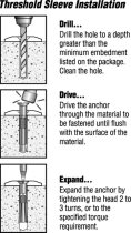
• Administer Epoxy into the hole prior to inserting the drop in anchor.
• Drive the anchor flush with the surface of concrete (shown in picture A)
• Expand the anchor with the setting tool (provided). Anchor is properly
expanded when shoulder of the setting tool is flush with the top of
the anchor (shown in picture B).
• Global Lift has provided a bonding lug that you will need to drill & attach to the
lift, due to there is no means to bond to the drop in anchor’s. Please check
local & state codes.
• Now you are ready to install your Commercial Series Lift.
Picture A
Picture B
Feb 2012
/


