Mitsubishi Electric MELSEC iQ-R Motion Controller User manual
- Type
- User manual

MELSEC iQ-R Motion Controller
User's Manual
-R16MTCPU
-R32MTCPU
-R64MTCPU


1
SAFETY PRECAUTIONS
(Read these precautions before using this product.)
Before using this product, please read this manual and the relevant manuals carefully and pay full attention to safety to handle
the product correctly.
The precautions given in this manual are concerned with this product only. Refer to MELSEC iQ-R Module Configuration
Manual for a description of the PLC system safety precautions.
In this manual, the safety precautions are classified into two levels: " WARNING" and " CAUTION".
Under some circumstances, failure to observe the precautions given under " CAUTION" may lead to serious
consequences.
Observe the precautions of both levels because they are important for personal and system safety.
Make sure that the end users read this manual and then keep the manual in a safe place for future reference.
[Design Precautions]
WARNING
●Configure safety circuits external to the programmable controller to ensure that the entire system
operates safely even when a fault occurs in the external power supply or the programmable controller.
Failure to do so may result in an accident due to an incorrect output or malfunction.
(1) Emergency stop circuits, protection circuits, and protective interlock circuits for conflicting
operations (such as forward/reverse rotations or upper/lower limit positioning) must be configured
external to the programmable controller.
(2) When the programmable controller detects an abnormal condition, it stops the operation and all
outputs are:
• Turned off if the overcurrent or overvoltage protection of the power supply module is activated.
• Held or turned off according to the parameter setting if the self-diagnostic function of the CPU
module detects an error such as a watchdog timer error.
(3) All outputs may be turned on if an error occurs in a part, such as an I/O control part, where the
CPU module cannot detect any error. To ensure safety operation in such a case, provide a safety
mechanism or a fail-safe circuit external to the programmable controller. For a fail-safe circuit
example, refer to "General Safety Requirements" in the MELSEC iQ-R Module Configuration
Manual.
(4) Outputs may remain on or off due to a failure of a component such as a relay and transistor in an
output circuit. Configure an external circuit for monitoring output signals that could cause a
serious accident.
●In an output circuit, when a load current exceeding the rated current or an overcurrent caused by a
load short-circuit flows for a long time, it may cause smoke and fire. To prevent this, configure an
external safety circuit, such as a fuse.
●Configure a circuit so that the programmable controller is turned on first and then the external power
supply. If the external power supply is turned on first, an accident may occur due to an incorrect output
or malfunction.
WARNING
Indicates that incorrect handling may cause hazardous conditions, resulting in
death or severe injury.
CAUTION
Indicates that incorrect handling may cause hazardous conditions, resulting in
minor or moderate injury or property damage.

2
[Design Precautions]
WARNING
●Configure a circuit so that the external power supply is turned off first and then the programmable
controller. If the programmable controller is turned off first, an accident may occur due to an incorrect
output or malfunction.
●For the operating status of each station after a communication failure, refer to manuals for the network
used. For the manuals, please consult your local Mitsubishi representative. Incorrect output or
malfunction due to a communication failure may result in an accident.
●When connecting an external device with a CPU module or intelligent function module to modify data
of a running programmable controller, configure an interlock circuit in the program to ensure that the
entire system will always operate safely. For other forms of control (such as program modification,
parameter change, forced output, or operating status change) of a running programmable controller,
read the relevant manuals carefully and ensure that the operation is safe before proceeding. Improper
operation may damage machines or cause accidents. When a Safety CPU is used, data cannot be
modified while the Safety CPU is in SAFETY MODE.
●Especially, when a remote programmable controller is controlled by an external device, immediate
action cannot be taken if a problem occurs in the programmable controller due to a communication
failure. To prevent this, configure an interlock circuit in the program, and determine corrective actions
to be taken between the external device and CPU module in case of a communication failure.
●Do not write any data to the "system area" and "write-protect area" of the buffer memory in the
module. Also, do not use any "use prohibited" signals as an output signal from the CPU module to
each module. Doing so may cause malfunction of the programmable controller system. For the
"system area", "write-protect area", and the "use prohibited" signals, refer to the user's manual for the
module used. For areas used for safety communications, they are protected from being written by
users, and thus safety communications failure caused by data writing does not occur.
●If a communication cable is disconnected, the network may be unstable, resulting in a communication
failure of multiple stations. Configure an interlock circuit in the program to ensure that the entire
system will always operate safely even if communications fail. Failure to do so may result in an
accident due to an incorrect output or malfunction. When safety communications are used, an
interlock by the safety station interlock function protects the system from an incorrect output or
malfunction.
●Configure safety circuits external to the programmable controller to ensure that the entire system
operates safely even when a fault occurs in the external power supply or the programmable controller.
Failure to do so may result in an accident due to an incorrect output or malfunction.
●If safety standards (ex., robot safety rules, etc.,) apply to the system using the module, servo amplifier
and servo motor, make sure that the safety standards are satisfied.
●Construct a safety circuit externally of the module or servo amplifier if the abnormal operation of the
module or servo amplifier differs from the safety directive operation in the system.
●Do not remove the SSCNET cable while turning on the control circuit power supply of modules and
servo amplifier. Do not see directly the light generated from SSCNET connector of the module or
servo amplifier and the end of SSCNET cable. When the light gets into eyes, you may feel
something wrong with eyes. (The light source of SSCNET complies with class 1 defined in
JISC6802 or IEC60825-1.)

3
[Design Precautions]
[Security Precautions]
[Installation Precautions]
CAUTION
●Do not install the control lines or communication cables together with the main circuit lines or power
cables. Doing so may result in malfunction due to electromagnetic interference. Keep a distance of
100mm or more between those cables.
●During control of an inductive load such as a lamp, heater, or solenoid valve, a large current
(approximately ten times greater than normal) may flow when the output is turned from off to on.
Therefore, use a module that has a sufficient current rating.
●After the CPU module is powered on or is reset, the time taken to enter the RUN status varies
depending on the system configuration, parameter settings, and/or program size. Design circuits so
that the entire system will always operate safely, regardless of the time.
●Do not power off the programmable controller or reset the CPU module while the settings are being
written. Doing so will make the data in the flash ROM and SD memory card undefined. The values
need to be set in the buffer memory and written to the flash ROM and SD memory card again. Doing
so also may cause malfunction or failure of the module.
●When changing the operating status of the CPU module from external devices (such as the remote
RUN/STOP functions), select "Do Not Open by Program" for "Opening Method" of "Module
Parameter". If "Open by Program" is selected, an execution of the remote STOP function causes the
communication line to close. Consequently, the CPU module cannot reopen the line, and external
devices cannot execute the remote RUN function.
WARNING
●To maintain the security (confidentiality, integrity, and availability) of the programmable controller and
the system against unauthorized access, denial-of-service (DoS) attacks, computer viruses, and other
cyberattacks from external devices via the network, take appropriate measures such as firewalls,
virtual private networks (VPNs), and antivirus solutions.
WARNING
●Shut off the external power supply (all phases) used in the system before mounting or removing the
module. Failure to do so may result in electric shock or cause the module to fail or malfunction.

4
[Installation Precautions]
[Wiring Precautions]
CAUTION
●Use the programmable controller in an environment that meets the general specifications in the Safety
Guidelines (IB-0800525). Failure to do so may result in electric shock, fire, malfunction, or damage to
or deterioration of the product.
●To mount a module, place the concave part(s) located at the bottom onto the guide(s) of the base unit,
and push in the module until the hook(s) located at the top snaps into place. Incorrect interconnection
may cause malfunction, failure, or drop of the module.
●To mount a module with no module fixing hook, place the concave part(s) located at the bottom onto
the guide(s) of the base unit, push in the module, and fix it with screw(s). Incorrect interconnection
may cause malfunction, failure, or drop of the module.
●When using the programmable controller in an environment of frequent vibrations, fix the module with
a screw.
●Tighten the screws within the specified torque range. Undertightening can cause drop of the
component or wire, short circuit, or malfunction. Overtightening can damage the screw and/or module,
resulting in drop, short circuit, or malfunction. For the specified torque range, refer to the MELSEC iQ-
R Module Configuration Manual.
●When using an extension cable, connect it to the extension cable connector of the base unit securely.
Check the connection for looseness. Poor contact may cause malfunction.
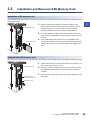
●When using an SD memory card, fully insert it into the SD memory card slot. Check that it is inserted
completely. Poor contact may cause malfunction.
●Securely insert an extended SRAM cassette or a battery-less option cassette into the cassette
connector of the CPU module. After insertion, close the cassette cover and check that the cassette is
inserted completely. Poor contact may cause malfunction.
●Beware that the module could be very hot while power is on and immediately after power-off.
●Do not directly touch any conductive parts and electronic components of the module, SD memory
card, extended SRAM cassette, battery-less option cassette, or connector. Doing so can cause
malfunction or failure of the module.
WARNING
●Shut off the external power supply (all phases) used in the system before installation and wiring.
Failure to do so may result in electric shock or cause the module to fail or malfunction.
●After installation and wiring, attach a blank cover module (RG60) to each empty slot before powering
on the system for operation. Also, attach an extension connector protective cover*1 to each unused
extension cable connector as necessary. Directly touching any conductive parts of the connectors
while power is on may result in electric shock.
*1 For details, please consult your local Mitsubishi Electric representative.

5
[Wiring Precautions]
CAUTION
●Individually ground the FG and LG terminals of the programmable controller with a ground resistance
of 100 ohms or less. Failure to do so may result in electric shock or malfunction.
●Use applicable solderless terminals and tighten them within the specified torque range. If any spade
solderless terminal is used, it may be disconnected when the terminal screw comes loose, resulting in
failure.
●Check the rated voltage and signal layout before wiring to the module, and connect the cables
correctly. Connecting a power supply with a different voltage rating or incorrect wiring may cause fire
or failure.
●Connectors for external devices must be crimped or pressed with the tool specified by the
manufacturer, or must be correctly soldered. Incomplete connections may cause short circuit, fire, or
malfunction.
●Securely connect the connector to the module. Poor contact may cause malfunction.
●Do not install the control lines or communication cables together with the main circuit lines or power
cables. Doing so may result in malfunction due to noise. Keep a distance of 100mm or more between
those cables.
●Place the cables in a duct or clamp them. If not, dangling cables may swing or inadvertently be pulled,
resulting in malfunction or damage to modules or cables.
In addition, the weight of the cables may put stress on modules in an environment of strong vibrations
and shocks.
Do not clamp the extension cables with the jacket stripped. Doing so may change the characteristics
of the cables, resulting in malfunction.
●Check the interface type and correctly connect the cable. Incorrect wiring (connecting the cable to an
incorrect interface) may cause failure of the module and external device.
●Tighten the terminal screws or connector screws within the specified torque range. Undertightening
can cause drop of the screw, short circuit, fire, or malfunction. Overtightening can damage the screw
and/or module, resulting in drop, short circuit, fire, or malfunction.
●When disconnecting the cable from the module, do not pull the cable by the cable part. For the cable
with connector, hold the connector part of the cable. For the cable connected to the terminal block,
loosen the terminal screw. Pulling the cable connected to the module may result in malfunction or
damage to the module or cable.
●Prevent foreign matter such as dust or wire chips from entering the module. Such foreign matter can
cause a fire, failure, or malfunction.
●When a protective film is attached to the top of the module, remove it before system operation.
If not, inadequate heat dissipation of the module may cause a fire, failure, or malfunction.
●Programmable controllers must be installed in control panels. Connect the main power supply to the
power supply module in the control panel through a relay terminal block. Wiring and replacement of a
power supply module must be performed by qualified maintenance personnel with knowledge of
protection against electric shock. For wiring, refer to the MELSEC iQ-R Module Configuration Manual.
●For Ethernet cables to be used in the system, select the ones that meet the specifications in the user's
manual for the module used. If not, normal data transmission is not guaranteed.

6
[Startup and Maintenance Precautions]
[Startup and Maintenance Precautions]
WARNING
●Do not touch any terminal while power is on. Doing so will cause electric shock or malfunction.
●Correctly connect the battery connector. Do not charge, disassemble, heat, short-circuit, solder, or
throw the battery into the fire. Also, do not expose it to liquid or strong shock. Doing so will cause the
battery to produce heat, explode, ignite, or leak, resulting in injury and fire.
●Shut off the external power supply (all phases) used in the system before cleaning the module or
retightening the terminal screws, connector screws, or module fixing screws. Failure to do so may
result in electric shock.
CAUTION
●When connecting an external device with a CPU module or intelligent function module to modify data
of a running programmable controller, configure an interlock circuit in the program to ensure that the
entire system will always operate safely. For other forms of control (such as program modification,
parameter change, forced output, or operating status change) of a running programmable controller,
read the relevant manuals carefully and ensure that the operation is safe before proceeding. Improper
operation may damage machines or cause accidents.
●Especially, when a remote programmable controller is controlled by an external device, immediate
action cannot be taken if a problem occurs in the programmable controller due to a communication
failure. To prevent this, configure an interlock circuit in the program, and determine corrective actions
to be taken between the external device and CPU module in case of a communication failure.
●Do not disassemble or modify the modules. Doing so may cause failure, malfunction, injury, or a fire.
●Use any radio communication device such as a cellular phone or PHS (Personal Handy-phone
System) more than 25cm away in all directions from the programmable controller. Failure to do so
may cause malfunction.
●Shut off the external power supply (all phases) used in the system before mounting or removing the
module. Failure to do so may cause the module to fail or malfunction.
●Tighten the screws within the specified torque range. Undertightening can cause drop of the
component or wire, short circuit, or malfunction. Overtightening can damage the screw and/or module,
resulting in drop, short circuit, or malfunction.
●After the first use of the product, do not perform each of the following operations more than 50 times
(IEC 61131-2/JIS B 3502 compliant).
Exceeding the limit may cause malfunction.
• Mounting/removing the module to/from the base unit
• Inserting/removing the extended SRAM cassette or battery-less option cassette to/from the
CPU module
• Mounting/removing the terminal block to/from the module
• Connecting/disconnecting the extension cable to/from the base unit
●After the first use of the product, do not insert/remove the SD memory card to/from the CPU module
more than 500 times. Exceeding the limit may cause malfunction.
●Do not touch the metal terminals on the back side of the SD memory card. Doing so may cause
malfunction or failure of the module.
●Do not touch the integrated circuits on the circuit board of an extended SRAM cassette or a battery-
less option cassette. Doing so may cause malfunction or failure of the module.

7
[Startup and Maintenance Precautions]
[Operating Precautions]
CAUTION
●Do not drop or apply shock to the battery to be installed in the module. Doing so may damage the
battery, causing the battery fluid to leak inside the battery. If the battery is dropped or any shock is
applied to it, dispose of it without using.
●Startup and maintenance of a control panel must be performed by qualified maintenance personnel
with knowledge of protection against electric shock. Lock the control panel so that only qualified
maintenance personnel can operate it.
●Before handling the module, touch a conducting object such as a grounded metal to discharge the
static electricity from the human body. Wearing a grounded antistatic wrist strap is recommended.
Failure to discharge the static electricity may cause the module to fail or malfunction.
●Use a clean and dry cloth to wipe off dirt on the module.
●Before testing the operation, set a low speed value for the speed limit parameter so that the operation
can be stopped immediately upon occurrence of a hazardous condition.
●Confirm and adjust the program and each parameter before operation. Unpredictable movements
may occur depending on the machine.
●When using the absolute position system function, on starting up, and when the module or absolute
position motor has been replaced, always perform a home position return.
●Before starting the operation, confirm the brake function.
●Do not perform a megger test (insulation resistance measurement) during inspection.
●After maintenance and inspections are completed, confirm that the position detection of the absolute
position detection function is correct.
●Lock the control panel and prevent access to those who are not certified to handle or install electric
equipment.
CAUTION
●When changing data and operating status, and modifying program of the running programmable
controller from an external device such as a personal computer connected to an intelligent function
module, read relevant manuals carefully and ensure the safety before operation. Incorrect change or
modification may cause system malfunction, damage to the machines, or accidents.
●Do not power off the programmable controller or reset the CPU module while the setting values in the
buffer memory are being written to the flash ROM in the module. Doing so will make the data in the
flash ROM and SD memory card undefined. The values need to be set in the buffer memory and
written to the flash ROM and SD memory card again. Doing so also may cause malfunction or failure
of the module.
●Note that when the reference axis speed is specified for interpolation operation, the speed of the
partner axis (2nd, 3rd, or 4th axis) may exceed the speed limit value.
●Do not go near the machine during test operations or during operations such as teaching. Doing so
may lead to injuries.

8
[Disposal Precautions]
[Transportation Precautions]
CAUTION
●When disposing of this product, treat it as industrial waste.
●When disposing of batteries, separate them from other wastes according to the local regulations. For
details on battery regulations in EU member states, refer to the MELSEC iQ-R Module Configuration
Manual.
CAUTION
●When transporting lithium batteries, follow the transportation regulations. For details on the regulated
models, refer to the MELSEC iQ-R Module Configuration Manual.
●The halogens (such as fluorine, chlorine, bromine, and iodine), which are contained in a fumigant
used for disinfection and pest control of wood packaging materials, may cause failure of the product.
Prevent the entry of fumigant residues into the product or consider other methods (such as heat
treatment) instead of fumigation. The disinfection and pest control measures must be applied to
unprocessed raw wood.

9
CONDITIONS OF USE FOR THE PRODUCT
INTRODUCTION
Thank you for purchasing the Mitsubishi Electric MELSEC iQ-R series programmable controllers.
This manual describes the system configuration, specifications, installation, wiring, maintenance and inspection, and
troubleshooting of the relevant products listed below.
Before using this product, please read this manual and the relevant manuals carefully and develop familiarity with the
functions and performance of the MELSEC iQ-R series programmable controller to handle the product correctly.
When applying the program examples provided in this manual to an actual system, ensure the applicability and confirm that it
will not cause system control problems.
Please make sure that the end users read this manual.
Relevant products
R16MTCPU, R32MTCPU, R64MTCPU
(1) MELSEC programmable controller ("the PRODUCT") shall be used in conditions;
i) where any problem, fault or failure occurring in the PRODUCT, if any, shall not lead to any major or serious accident;
and
ii) where the backup and fail-safe function are systematically or automatically provided outside of the PRODUCT for the
case of any problem, fault or failure occurring in the PRODUCT.
(2) The PRODUCT has been designed and manufactured for the purpose of being used in general industries.
MITSUBISHI ELECTRIC SHALL HAVE NO RESPONSIBILITY OR LIABILITY (INCLUDING, BUT NOT LIMITED TO
ANY AND ALL RESPONSIBILITY OR LIABILITY BASED ON CONTRACT, WARRANTY, TORT, PRODUCT
LIABILITY) FOR ANY INJURY OR DEATH TO PERSONS OR LOSS OR DAMAGE TO PROPERTY CAUSED BY the
PRODUCT THAT ARE OPERATED OR USED IN APPLICATION NOT INTENDED OR EXCLUDED BY
INSTRUCTIONS, PRECAUTIONS, OR WARNING CONTAINED IN MITSUBISHI ELECTRIC USER'S, INSTRUCTION
AND/OR SAFETY MANUALS, TECHNICAL BULLETINS AND GUIDELINES FOR the PRODUCT.
("Prohibited Application")
Prohibited Applications include, but not limited to, the use of the PRODUCT in;
• Nuclear Power Plants and any other power plants operated by Power companies, and/or any other cases in which the
public could be affected if any problem or fault occurs in the PRODUCT.
• Railway companies or Public service purposes, and/or any other cases in which establishment of a special quality
assurance system is required by the Purchaser or End User.
• Aircraft or Aerospace, Medical applications, Train equipment, transport equipment such as Elevator and Escalator,
Incineration and Fuel devices, Vehicles, Manned transportation, Equipment for Recreation and Amusement, and
Safety devices, handling of Nuclear or Hazardous Materials or Chemicals, Mining and Drilling, and/or other
applications where there is a significant risk of injury to the public or property.
Notwithstanding the above restrictions, Mitsubishi Electric may in its sole discretion, authorize use of the PRODUCT in
one or more of the Prohibited Applications, provided that the usage of the PRODUCT is limited only for the specific
applications agreed to by Mitsubishi Electric and provided further that no special quality assurance or fail-safe,
redundant or other safety features which exceed the general specifications of the PRODUCTs are required. For details,
please contact the Mitsubishi Electric representative in your region.
(3) Mitsubishi Electric shall have no responsibility or liability for any problems involving programmable controller trouble and
system trouble caused by DoS attacks, unauthorized access, computer viruses, and other cyberattacks.

10
COMPLIANCE WITH EMC AND LOW VOLTAGE
DIRECTIVES
Method of ensuring compliance
To ensure that Mitsubishi programmable controllers maintain EMC and Low Voltage Directives when incorporated into other
machinery or equipment, certain measures may be necessary. Please refer to one of the following manuals.
MELSEC iQ-R Module Configuration Manual (SH-081262ENG)
Safety Guidelines (This manual is included with the base unit.) (IB-0800525)
The CE mark on the side of the programmable controller indicates compliance with EMC and Low Voltage Directives.
Additional measures
To ensure that this product maintains EMC and Low Voltage Directives, please refer to the following manual.
MELSEC iQ-R Motion Controller User's Manual (IB-0300235)

11
CONTENTS
CONTENTS
SAFETY PRECAUTIONS . . . . . . . . . . . . . . . . . . . . . . . . . . . . . . . . . . . . . . . . . . . . . . . . . . . . . . . . . . . . . . . . . . . .1
CONDITIONS OF USE FOR THE PRODUCT . . . . . . . . . . . . . . . . . . . . . . . . . . . . . . . . . . . . . . . . . . . . . . . . . . . .9
INTRODUCTION. . . . . . . . . . . . . . . . . . . . . . . . . . . . . . . . . . . . . . . . . . . . . . . . . . . . . . . . . . . . . . . . . . . . . . . . . . .9
COMPLIANCE WITH EMC AND LOW VOLTAGE DIRECTIVES . . . . . . . . . . . . . . . . . . . . . . . . . . . . . . . . . . . . .10
RELEVANT MANUALS . . . . . . . . . . . . . . . . . . . . . . . . . . . . . . . . . . . . . . . . . . . . . . . . . . . . . . . . . . . . . . . . . . . . .13
TERMS . . . . . . . . . . . . . . . . . . . . . . . . . . . . . . . . . . . . . . . . . . . . . . . . . . . . . . . . . . . . . . . . . . . . . . . . . . . . . . . . .14
MANUAL PAGE ORGANISATION. . . . . . . . . . . . . . . . . . . . . . . . . . . . . . . . . . . . . . . . . . . . . . . . . . . . . . . . . . . . .15
DISCONTINUED MODELS . . . . . . . . . . . . . . . . . . . . . . . . . . . . . . . . . . . . . . . . . . . . . . . . . . . . . . . . . . . . . . . . .15
CHAPTER 1 SYSTEM CONFIGURATION 16
1.1 Motion System Configuration . . . . . . . . . . . . . . . . . . . . . . . . . . . . . . . . . . . . . . . . . . . . . . . . . . . . . . . . . . . . . 16
Equipment configuration in system . . . . . . . . . . . . . . . . . . . . . . . . . . . . . . . . . . . . . . . . . . . . . . . . . . . . . . . . . . . 16
Peripheral device configuration . . . . . . . . . . . . . . . . . . . . . . . . . . . . . . . . . . . . . . . . . . . . . . . . . . . . . . . . . . . . . . 17
R64MTCPU/R32MTCPU/R16MTCPU system overall configuration. . . . . . . . . . . . . . . . . . . . . . . . . . . . . . . . . . 18
Function explanation of the Motion CPU modules . . . . . . . . . . . . . . . . . . . . . . . . . . . . . . . . . . . . . . . . . . . . . . . 19
Restrictions on Motion systems. . . . . . . . . . . . . . . . . . . . . . . . . . . . . . . . . . . . . . . . . . . . . . . . . . . . . . . . . . . . . . 19
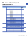
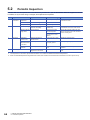
1.2 System Configuration Equipment . . . . . . . . . . . . . . . . . . . . . . . . . . . . . . . . . . . . . . . . . . . . . . . . . . . . . . . . . . 23
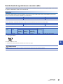
Configuration equipment list . . . . . . . . . . . . . . . . . . . . . . . . . . . . . . . . . . . . . . . . . . . . . . . . . . . . . . . . . . . . . . . . 23
Software packages . . . . . . . . . . . . . . . . . . . . . . . . . . . . . . . . . . . . . . . . . . . . . . . . . . . . . . . . . . . . . . . . . . . . . . . 28
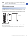
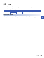
1.3 Checking Production Information and Operating System Software Version . . . . . . . . . . . . . . . . . . . . . . . 29
Checking production information. . . . . . . . . . . . . . . . . . . . . . . . . . . . . . . . . . . . . . . . . . . . . . . . . . . . . . . . . . . . . 29
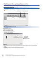
Checking operating system software version . . . . . . . . . . . . . . . . . . . . . . . . . . . . . . . . . . . . . . . . . . . . . . . . . . . 30
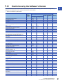
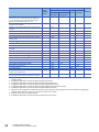
1.4 Restrictions by the Software's Version . . . . . . . . . . . . . . . . . . . . . . . . . . . . . . . . . . . . . . . . . . . . . . . . . . . . . . 31
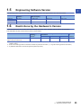
1.5 Engineering Software Version . . . . . . . . . . . . . . . . . . . . . . . . . . . . . . . . . . . . . . . . . . . . . . . . . . . . . . . . . . . . . 33
1.6 Restrictions by the Hardware's Version . . . . . . . . . . . . . . . . . . . . . . . . . . . . . . . . . . . . . . . . . . . . . . . . . . . . . 33
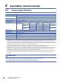
CHAPTER 2 EQUIPMENT SPECIFICATIONS 34
2.1 General Specifications . . . . . . . . . . . . . . . . . . . . . . . . . . . . . . . . . . . . . . . . . . . . . . . . . . . . . . . . . . . . . . . . . . . 34
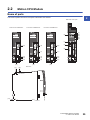
2.2 Motion CPU Module. . . . . . . . . . . . . . . . . . . . . . . . . . . . . . . . . . . . . . . . . . . . . . . . . . . . . . . . . . . . . . . . . . . . . . 35
Name of parts . . . . . . . . . . . . . . . . . . . . . . . . . . . . . . . . . . . . . . . . . . . . . . . . . . . . . . . . . . . . . . . . . . . . . . . . . . . 35
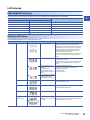
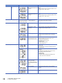
LED display . . . . . . . . . . . . . . . . . . . . . . . . . . . . . . . . . . . . . . . . . . . . . . . . . . . . . . . . . . . . . . . . . . . . . . . . . . . . . 37
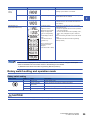
Rotary switch setting and operation mode . . . . . . . . . . . . . . . . . . . . . . . . . . . . . . . . . . . . . . . . . . . . . . . . . . . . . 39
Specifications . . . . . . . . . . . . . . . . . . . . . . . . . . . . . . . . . . . . . . . . . . . . . . . . . . . . . . . . . . . . . . . . . . . . . . . . . . . 42
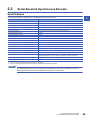
2.3 Serial Absolute Synchronous Encoder . . . . . . . . . . . . . . . . . . . . . . . . . . . . . . . . . . . . . . . . . . . . . . . . . . . . . . 45
Specifications . . . . . . . . . . . . . . . . . . . . . . . . . . . . . . . . . . . . . . . . . . . . . . . . . . . . . . . . . . . . . . . . . . . . . . . . . . . 45
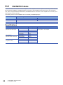
2.4 SSCNETIII Cables . . . . . . . . . . . . . . . . . . . . . . . . . . . . . . . . . . . . . . . . . . . . . . . . . . . . . . . . . . . . . . . . . . . . . . . 46
Specifications . . . . . . . . . . . . . . . . . . . . . . . . . . . . . . . . . . . . . . . . . . . . . . . . . . . . . . . . . . . . . . . . . . . . . . . . . . . 46
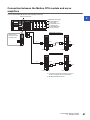
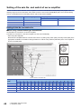
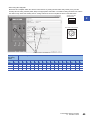
Connection between the Motion CPU module and servo amplifiers . . . . . . . . . . . . . . . . . . . . . . . . . . . . . . . . . .47
Setting of the axis No. and switch of servo amplifier . . . . . . . . . . . . . . . . . . . . . . . . . . . . . . . . . . . . . . . . . . . . . . 48
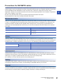
Precautions for SSCNETIII cables . . . . . . . . . . . . . . . . . . . . . . . . . . . . . . . . . . . . . . . . . . . . . . . . . . . . . . . . . . . 51
CHAPTER 3 INSTALLATION AND WIRING 54
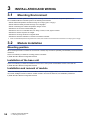
3.1 Mounting Environment . . . . . . . . . . . . . . . . . . . . . . . . . . . . . . . . . . . . . . . . . . . . . . . . . . . . . . . . . . . . . . . . . . . 54
3.2 Module Installation . . . . . . . . . . . . . . . . . . . . . . . . . . . . . . . . . . . . . . . . . . . . . . . . . . . . . . . . . . . . . . . . . . . . . . 54
Mounting position . . . . . . . . . . . . . . . . . . . . . . . . . . . . . . . . . . . . . . . . . . . . . . . . . . . . . . . . . . . . . . . . . . . . . . . . 54
Installation of the base unit . . . . . . . . . . . . . . . . . . . . . . . . . . . . . . . . . . . . . . . . . . . . . . . . . . . . . . . . . . . . . . . . . 54
Installation and removal of module . . . . . . . . . . . . . . . . . . . . . . . . . . . . . . . . . . . . . . . . . . . . . . . . . . . . . . . . . . . 54
3.3 Installation and Removal of SD Memory Card . . . . . . . . . . . . . . . . . . . . . . . . . . . . . . . . . . . . . . . . . . . . . . . . 55

12
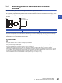
3.4 Mounting of Serial Absolute Synchronous Encoder . . . . . . . . . . . . . . . . . . . . . . . . . . . . . . . . . . . . . . . . . . . 57
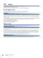
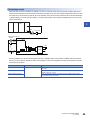
3.5 Wiring . . . . . . . . . . . . . . . . . . . . . . . . . . . . . . . . . . . . . . . . . . . . . . . . . . . . . . . . . . . . . . . . . . . . . . . . . . . . . . . . . 58
Power supply circuit. . . . . . . . . . . . . . . . . . . . . . . . . . . . . . . . . . . . . . . . . . . . . . . . . . . . . . . . . . . . . . . . . . . . . . . 58
Safety circuit . . . . . . . . . . . . . . . . . . . . . . . . . . . . . . . . . . . . . . . . . . . . . . . . . . . . . . . . . . . . . . . . . . . . . . . . . . . . 58
CHAPTER 4 START-UP PROCEDURES 60
4.1 Start-up Adjustment Procedure . . . . . . . . . . . . . . . . . . . . . . . . . . . . . . . . . . . . . . . . . . . . . . . . . . . . . . . . . . . . 60
CHAPTER 5 INSPECTION AND MAINTENANCE 63
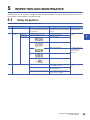
5.1 Daily Inspection . . . . . . . . . . . . . . . . . . . . . . . . . . . . . . . . . . . . . . . . . . . . . . . . . . . . . . . . . . . . . . . . . . . . . . . . . 63
5.2 Periodic Inspection . . . . . . . . . . . . . . . . . . . . . . . . . . . . . . . . . . . . . . . . . . . . . . . . . . . . . . . . . . . . . . . . . . . . . . 64
5.3 Life . . . . . . . . . . . . . . . . . . . . . . . . . . . . . . . . . . . . . . . . . . . . . . . . . . . . . . . . . . . . . . . . . . . . . . . . . . . . . . . . . . . 65
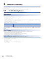
CHAPTER 6 TROUBLESHOOTING 66
6.1 Troubleshooting Basics . . . . . . . . . . . . . . . . . . . . . . . . . . . . . . . . . . . . . . . . . . . . . . . . . . . . . . . . . . . . . . . . . . 66
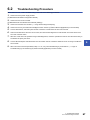
6.2 Troubleshooting Procedure . . . . . . . . . . . . . . . . . . . . . . . . . . . . . . . . . . . . . . . . . . . . . . . . . . . . . . . . . . . . . . . 67
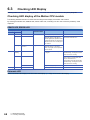
6.3 Checking LED Display . . . . . . . . . . . . . . . . . . . . . . . . . . . . . . . . . . . . . . . . . . . . . . . . . . . . . . . . . . . . . . . . . . . 68
Checking LED display of the Motion CPU module . . . . . . . . . . . . . . . . . . . . . . . . . . . . . . . . . . . . . . . . . . . . . . . 68
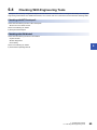
6.4 Checking With Engineering Tools . . . . . . . . . . . . . . . . . . . . . . . . . . . . . . . . . . . . . . . . . . . . . . . . . . . . . . . . . . 69
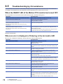
6.5 Troubleshooting by Circumstance . . . . . . . . . . . . . . . . . . . . . . . . . . . . . . . . . . . . . . . . . . . . . . . . . . . . . . . . . 70
When the READY LED of the Motion CPU module has turned OFF . . . . . . . . . . . . . . . . . . . . . . . . . . . . . . . . . 70
When an error is displayed or flickering in the dot matrix LED . . . . . . . . . . . . . . . . . . . . . . . . . . . . . . . . . . . . . . 70
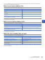
When cannot write to Motion CPU . . . . . . . . . . . . . . . . . . . . . . . . . . . . . . . . . . . . . . . . . . . . . . . . . . . . . . . . . . . 71
When cannot read from Motion CPU. . . . . . . . . . . . . . . . . . . . . . . . . . . . . . . . . . . . . . . . . . . . . . . . . . . . . . . . . . 71
When the servo amplifier does not start . . . . . . . . . . . . . . . . . . . . . . . . . . . . . . . . . . . . . . . . . . . . . . . . . . . . . . . 71
CHAPTER 7 EMC DIRECTIVES 72
7.1 Requirements for Compliance with the EMC Directive . . . . . . . . . . . . . . . . . . . . . . . . . . . . . . . . . . . . . . . . . 72
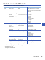
Standards relevant to the EMC directive . . . . . . . . . . . . . . . . . . . . . . . . . . . . . . . . . . . . . . . . . . . . . . . . . . . . . . . 73
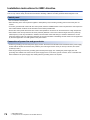
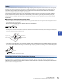
Installation instructions for EMC directive . . . . . . . . . . . . . . . . . . . . . . . . . . . . . . . . . . . . . . . . . . . . . . . . . . . . . . 74
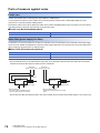
Parts of measure against noise . . . . . . . . . . . . . . . . . . . . . . . . . . . . . . . . . . . . . . . . . . . . . . . . . . . . . . . . . . . . . . 76
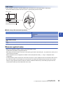
Measure against noise . . . . . . . . . . . . . . . . . . . . . . . . . . . . . . . . . . . . . . . . . . . . . . . . . . . . . . . . . . . . . . . . . . . . 77
APPENDICES 78
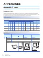
Appendix 1 Cables . . . . . . . . . . . . . . . . . . . . . . . . . . . . . . . . . . . . . . . . . . . . . . . . . . . . . . . . . . . . . . . . . . . . . . . . . . . . 78
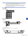
SSCNETIII cables . . . . . . . . . . . . . . . . . . . . . . . . . . . . . . . . . . . . . . . . . . . . . . . . . . . . . . . . . . . . . . . . . . . . . . . . 78
Serial absolute synchronous encoder cable . . . . . . . . . . . . . . . . . . . . . . . . . . . . . . . . . . . . . . . . . . . . . . . . . . . . 81
SSCNETIII cables (SC-J3BUS□M-C) manufactured by Mitsubishi Electric System & Service. . . . . . . . . . . . . . 83
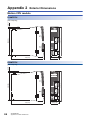
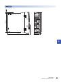
Appendix 2 Exterior Dimensions . . . . . . . . . . . . . . . . . . . . . . . . . . . . . . . . . . . . . . . . . . . . . . . . . . . . . . . . . . . . . . . . 84
Motion CPU module . . . . . . . . . . . . . . . . . . . . . . . . . . . . . . . . . . . . . . . . . . . . . . . . . . . . . . . . . . . . . . . . . . . . . . 84
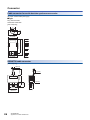
Connector . . . . . . . . . . . . . . . . . . . . . . . . . . . . . . . . . . . . . . . . . . . . . . . . . . . . . . . . . . . . . . . . . . . . . . . . . . . . . . 86
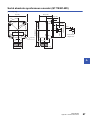
Serial absolute synchronous encoder (Q171ENC-W8) . . . . . . . . . . . . . . . . . . . . . . . . . . . . . . . . . . . . . . . . . . . . 87
REVISIONS. . . . . . . . . . . . . . . . . . . . . . . . . . . . . . . . . . . . . . . . . . . . . . . . . . . . . . . . . . . . . . . . . . . . . . . . . . . . . .88
WARRANTY . . . . . . . . . . . . . . . . . . . . . . . . . . . . . . . . . . . . . . . . . . . . . . . . . . . . . . . . . . . . . . . . . . . . . . . . . . . . .89
TRADEMARKS . . . . . . . . . . . . . . . . . . . . . . . . . . . . . . . . . . . . . . . . . . . . . . . . . . . . . . . . . . . . . . . . . . . . . . . . . . .90

13
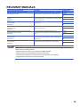
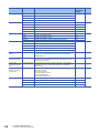
RELEVANT MANUALS
e-Manual refers to the Mitsubishi FA electronic book manuals that can be browsed using a dedicated tool.
e-Manual has the following features:
• Required information can be cross-searched in multiple manuals.
• Other manuals can be accessed from the links in the manual.
• The hardware specifications of each part can be found from the product figures.
• Pages that users often browse can be bookmarked.
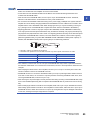
Manual Name [Manual Number] Description Available form
MELSEC iQ-R Motion Controller User's Manual
[IB-0300235] (This manual)
This manual explains specifications of the Motion CPU modules,
SSCNET cables, synchronous encoder, troubleshooting, etc.
Print book
e-Manual
PDF
MELSEC iQ-R Motion Controller Programming Manual
(Common)
[IB-0300237]
This manual explains the Multiple CPU system configuration,
performance specifications, common parameters, auxiliary/applied
functions, error lists, etc.
Print book
e-Manual
PDF
MELSEC iQ-R Motion Controller Programming Manual
(Program Design)
[IB-0300239]
This manual explains the functions, programming, debugging for
Motion SFC, etc.
Print book
e-Manual
PDF
MELSEC iQ-R Motion Controller Programming Manual
(Positioning Control)
[IB-0300241]
This manual explains the servo parameters, positioning
instructions, device lists, etc.
Print book
e-Manual
PDF
MELSEC iQ-R Motion Controller Programming Manual
(Advanced Synchronous Control)
[IB-0300243]
This manual explains the dedicated instructions to use
synchronous control by synchronous control parameters, device
lists, etc.
Print book
e-Manual
PDF
MELSEC iQ-R Motion Controller Programming Manual
(Machine Control)
[IB-0300309]
This manual explains the dedicated instructions to use machine
control by machine control parameters, machine positioning data,
device lists, etc.
Print book
e-Manual
PDF
MELSEC iQ-R Motion Controller Programming Manual
(G-Code Control)
[IB-0300371]
This manual explains the dedicated instructions to use G-code
control by G-code control parameters and G-code programs.
Print book
e-Manual
PDF

14
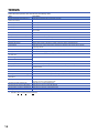
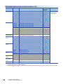
TERMS
Unless otherwise specified, this manual uses the following terms.
*1 SSCNET: Servo System Controller NETwork
Term Description
R64MTCPU/R32MTCPU/R16MTCPU or
Motion CPU (module)
Abbreviation for MELSEC iQ-R series Motion controller
MR-J5(W)-B Servo amplifier model MR-J5-B/MR-J5W-B
MR-J4(W)-B Servo amplifier model MR-J4-B/MR-J4W-B
MR-J3(W)-B Servo amplifier model MR-J3-B/MR-J3W-B
AMP or Servo amplifier General name for "Servo amplifier model MR-J5-B/MR-J5W-B/MR-J4-B/MR-J4W-B/MR-J3-B/
MR-J3W-B"
RnCPU, PLC CPU or PLC CPU module Abbreviation for MELSEC iQ-R series CPU module
Multiple CPU system or Motion system Abbreviation for "Multiple PLC system of the R series"
CPUn Abbreviation for "CPU No.n (n = 1 to 4) of the CPU module for the Multiple CPU system"
Operating system software General name for "SW10DNC-RMTFW"
Engineering tool General name for MT Developer2/GX Works3/GX LogViewer
MELSOFT MT Works2 General product name for the Motion controller engineering software "SW1DND-MTW2"
MT Developer2 Abbreviation for the programming software included in the "MELSOFT MT Works2" Motion controller
engineering software
GX Works3 General product name for the MELSEC PLC software package "SW1DND-GXW3"
GX LogViewer Product name for the logging data display and analysis tool "SW1DNN-VIEWER"
Serial absolute synchronous encoder or
Q171ENC-W8
Abbreviation for "Serial absolute synchronous encoder (Q171ENC-W8)"
SSCNET/H*1 High speed synchronous network between Motion controller and servo amplifier
SSCNET*1
SSCNET(/H) General name for SSCNET/H, SSCNET
Absolute position system General name for "system using the servo motor and servo amplifier for absolute position"
Intelligent function module General name for module that has a function other than input or output such as A/D converter module and D/A
converter module.
SSCNET/H head module*1 Abbreviation for "MELSEC-L series SSCNET/H head module (LJ72MS15)"
Optical hub unit or MR-MV200 Abbreviation for SSCNET/H Compatible Optical Hub Unit (MR-MV200)
Sensing module General name for SSCNET/H compatible sensing module MR-MT2000 series
Sensing SSCNET/H head module*1 or
MR-MT2010
Abbreviation for SSCNET/H head module (MR-MT2010)
Sensing extension module General name for I/O module (MR-MT2100), pulse I/O module (MR-MT2200), analog I/O module (MR-
MT2300), encoder I/F module (MR-MT2400)
Sensing I/O module or MR-MT2100 Abbreviation for I/O module (MR-MT2100)
Sensing pulse I/O module or MR-MT2200 Abbreviation for pulse I/O module (MR-MT2200)
Sensing analog I/O module or MR-MT2300 Abbreviation for analog I/O module (MR-MT2300)
Sensing encoder I/F module or MR-MT2400 Abbreviation for encoder I/F module (MR-MT2400)

15
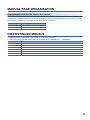
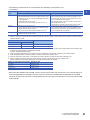
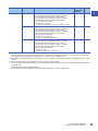
MANUAL PAGE ORGANISATION
Representation of device No. used in this manual
The "R" and "Q" beside the device No. of positioning dedicated signals such as "[Rq.1140] Stop command (R: M34480+32n/
Q: M3200+20n)" indicate the device No. for the device assignment methods shown below. When "R" and "Q" are not beside
the device No., the device No. is the same for both device assignment methods.
DISCONTINUED MODELS
The following models are described in this manual, but are no longer produced.
For the onerous repair term after discontinuation of production, refer to "WARRANTY" (WARRANTY).
Symbol Device assignment method
R MELSEC iQ-R Motion device assignment
Q Q series Motion compatible device assignment
Model Production discontinuation
MR-J3-B May 2019
MR-J3W-B May 2019
MR-J3-B-RJ006 May 2019
MR-J3-B-RJ004 May 2019
MR-J3-B-RJ080W May 2019
MR-J3-BS May 2019

16 1 SYSTEM CONFIGURATION
1.1 Motion System Configuration
1SYSTEM CONFIGURATION
This section describes the Motion controller system configuration, precautions on use of system and configured equipment.
1.1 Motion System Configuration
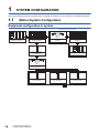
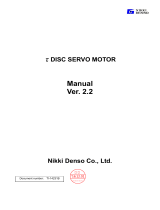
Equipment configuration in system
Extension of the R series module
Motion CPU module
(R64MTCPU/R32MTCPU/
R16MTCPU)
: Selected according to the system
Main base unit
(R33B, R35B, R38B,
R312B, R310B-HT)
Power supply module/RnCPU/
I/O module/Intelligent function
module of the R series
Power supply module/
I/O module/Intelligent function
module of the R series
Extension cable
(RCB)
Servo amplifier
(MR-J4(W)-B)
Servo amplifier
(MR-J5(W)-B)
Servo amplifier
(MR-J3(W)-B)
R6B extension base unit
(R65B, R68B, R612B,
R610B-HT)
SSCNETµcable
(MR-J3BUSM(-A/-B))

1 SYSTEM CONFIGURATION
1.1 Motion System Configuration 17
1
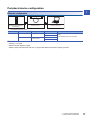
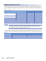
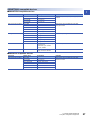
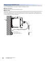
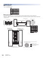
Peripheral device configuration
Ethernet configuration
*1 Corresponding Ethernet cables
■Selection criterion of cable
• Category : 5 or higher
• Diameter of lead: AWG26 or higher
• Shield: Copper braid shield and drain wire or copper braid shield and aluminium layered type shield
Part name Connection type Cable type Ethernet standard Specification
Ethernet cable Connection with HUB Straight cable 10BASE-T Compliant with Ethernet standards, category 5 or
higher.
• Shielded twisted pair cable (STP cable)
100BASE-TX
Direct connection Straight cable
Crossover cable
10BASE-T
100BASE-TX
Ethernet cable *1 Personal computer
Motion CPU module
(R64MTCPU/R32MTCPU/
R16MTCPU)

18 1 SYSTEM CONFIGURATION
1.1 Motion System Configuration
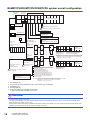
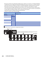
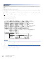
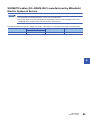
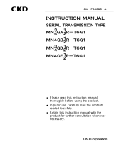
R64MTCPU/R32MTCPU/R16MTCPU system overall configuration
*1 MR-J4-B-RJ only
*2 Up to 16 axes per line for R64MTCPU when communication type is SSCNET.
*3 SSCNET/H only
*4 MR-J5(W)-B only
*5 Refer to the following for supported encoder cables.
Servo amplifier (MR-J5(W)-B) user's manual
CAUTION
• Construct a safety circuit externally of the Motion controller or servo amplifier if the abnormal operation of the Motion controller or servo amplifier differ from
the safety directive operation in the system.
• The ratings and characteristics of the parts (other than Motion controller, servo amplifier and servo motor) used in a system must be compatible with the
Motion controller, servo amplifier and servo motor.
• Set the parameter values to those that are compatible with the Motion controller, servo amplifier, servo motor and regenerative resistor model and the system
application. The protective functions may not function if the settings are incorrect.
RMT
CPU
RCPU
R61P
PLC CPU/
Motion CPU
Main base unit
(R3B)
Extension base unit
(R6B)
Extension cable
(RCB)
Up to 7 extensions
RX
Line 1
SSCNETµ(/H)
(CN1)
Line 2
SSCNETµ(/H)
(CN2)
SSCNETµ cable
(MR-J3BUSM(-A/-B))
RY
Motion CPU controlled modules
RD62R6AD
/
R6DA
P Manual pulse generator x2/module
Incremental synchronous encoder x2/module
Intelligent
function module
E
I/O module/
Intelligent function module
Analog Input/Output
Input/Output
(Up to 4096 points)
External input signals
d01
M
E
d02 d16
M
E
d01
M
E
d02
M
E
M
E
d16
M
E
Power supply
module
Personal computer
GOT
USB/Ethernet
PERIPHERAL I/F
Cognex Corporation
vision system
Sensing module
MR-MT2000 series
*3
I/O module,
Intelligent
function module
L61P LJ72MS15
MELSEC-L series SSCNETµ/H
head module (LJ72MS15)
*3
Sensing module
MR-MT2000 series
*3
R64MTCPU: 2 lines (Up to 8 stations (Up to 4 stations/line))
R32MTCPU: 2 lines (Up to 8 stations (Up to 4 stations/line))
R16MTCPU: 1 line (Up to 4 stations)
I/O module,
Intelligent
function module
L61P LJ72MS15
R64MTCPU: 2 lines (Up to 64 axes (Up to 32 axes/line))
*2
R32MTCPU: 2 lines (Up to 32 axes (Up to 16 axes/line))
R16MTCPU: 1 line (Up to 16 axes)
External input signals of servo amplifier
E
E
MR-J5(W)-B/MR-J4(W)-B/MR-J3(W)-B
model servo amplifier
Optical hub unit (MR-MV200)
Inverter FR-A800/FR-A700 series
VC´ series/VPH series servo driver
manufactured by CKD Nikki Denso Co., Ltd.
Stepping motor module AlphaStep/5-phase
manufactured by ORIENTAL MOTOR Co., Ltd.
IAI electric actuator controller manufactured
by IAI Corporation
Upper stroke limit
Lower stroke limit
Stop signal
Proximity dog/Speed-position switching
Upper stroke limit
Lower stroke limit
Proximity dog/Speed-position switching
Serial absolute synchronous encoder
*1
(Q171ENC-W8)
Serial absolute synchronous
encoder cable
(Q170ENCCBLM-A)
Synchronous encoder
*4
(HK-KT motor)
Encoder cable
*5
Page is loading ...
Page is loading ...
Page is loading ...
Page is loading ...
Page is loading ...
Page is loading ...
Page is loading ...
Page is loading ...
Page is loading ...
Page is loading ...
Page is loading ...
Page is loading ...
Page is loading ...
Page is loading ...
Page is loading ...
Page is loading ...
Page is loading ...
Page is loading ...
Page is loading ...
Page is loading ...
Page is loading ...
Page is loading ...
Page is loading ...
Page is loading ...
Page is loading ...
Page is loading ...
Page is loading ...
Page is loading ...
Page is loading ...
Page is loading ...
Page is loading ...
Page is loading ...
Page is loading ...
Page is loading ...
Page is loading ...
Page is loading ...
Page is loading ...
Page is loading ...
Page is loading ...
Page is loading ...
Page is loading ...
Page is loading ...
Page is loading ...
Page is loading ...
Page is loading ...
Page is loading ...
Page is loading ...
Page is loading ...
Page is loading ...
Page is loading ...
Page is loading ...
Page is loading ...
Page is loading ...
Page is loading ...
Page is loading ...
Page is loading ...
Page is loading ...
Page is loading ...
Page is loading ...
Page is loading ...
Page is loading ...
Page is loading ...
Page is loading ...
Page is loading ...
Page is loading ...
Page is loading ...
Page is loading ...
Page is loading ...
Page is loading ...
Page is loading ...
Page is loading ...
Page is loading ...
Page is loading ...
Page is loading ...
-
 1
1
-
 2
2
-
 3
3
-
 4
4
-
 5
5
-
 6
6
-
 7
7
-
 8
8
-
 9
9
-
 10
10
-
 11
11
-
 12
12
-
 13
13
-
 14
14
-
 15
15
-
 16
16
-
 17
17
-
 18
18
-
 19
19
-
 20
20
-
 21
21
-
 22
22
-
 23
23
-
 24
24
-
 25
25
-
 26
26
-
 27
27
-
 28
28
-
 29
29
-
 30
30
-
 31
31
-
 32
32
-
 33
33
-
 34
34
-
 35
35
-
 36
36
-
 37
37
-
 38
38
-
 39
39
-
 40
40
-
 41
41
-
 42
42
-
 43
43
-
 44
44
-
 45
45
-
 46
46
-
 47
47
-
 48
48
-
 49
49
-
 50
50
-
 51
51
-
 52
52
-
 53
53
-
 54
54
-
 55
55
-
 56
56
-
 57
57
-
 58
58
-
 59
59
-
 60
60
-
 61
61
-
 62
62
-
 63
63
-
 64
64
-
 65
65
-
 66
66
-
 67
67
-
 68
68
-
 69
69
-
 70
70
-
 71
71
-
 72
72
-
 73
73
-
 74
74
-
 75
75
-
 76
76
-
 77
77
-
 78
78
-
 79
79
-
 80
80
-
 81
81
-
 82
82
-
 83
83
-
 84
84
-
 85
85
-
 86
86
-
 87
87
-
 88
88
-
 89
89
-
 90
90
-
 91
91
-
 92
92
-
 93
93
-
 94
94


Mitsubishi Electric MELSEC iQ-R Motion Controller User manual
- Type
- User manual
Ask a question and I''ll find the answer in the document
Finding information in a document is now easier with AI
Related papers
-
Mitsubishi Electric MELSEC iQ-R Motion Controller User manual
-
-
-
-
-
-
-
-
-
Other documents
-
FEC EnForce Digital Servo Press Operating instructions
-
 CKD VPH-HC Type User manual
-
 CKD VPH-HA Type User manual
-
 CKD VPH-HD Type User manual
-
 CKD VPH-HE Type User manual
-
 CKD AFB-RB Series User manual
-
 CKD τDISC Series User manual
-
-
 CKD 4GR-T6G1 Series(CC-Link) User manual
-
 CKD GCKW Series User manual


