Page is loading ...

MAINTENANCE
FRICK® QUANTUM™ HD
COMPRESSOR CONTROL PANEL
Version 10.21
Form 090.040-M (NOV 2016)
MAINTENANCE
File: SERVICE MANUAL - Section 90
Replaces: 090.040-M (APR 2016)
Dist: 3, 3a, 3b, 3c
Please check www.johnsoncontrols.com/frick for the latest version of this publication.

QUANTUM™ HD COMPRESSOR CONTROL PANEL
MAINTENANCE
090.040-M (NOV 2016)
Page 2
CONTENTS
SECTION 1 - CONTROL SYSTEM
INTRODUCTION ................................................................6
CONTROL PANEL ENCLOSURE ............................................6
GENERAL INFORMATION ....................................................6
WHAT TO DO BEFORE CALLING THE FACTORY ..................7
SECTION 2 - QUANTUM™ HD OPERATOR INTERFACE
DESCRIPTION ...................................................................10
DISPLAY ASSEMBLY .........................................................10
TOUCHSCREEN DESCRIPTION .......................................... 11
USING AN EXTERNAL USB STYLE
KEYBOARD OR MOUSE ...............................................11
SECTION 3 - Q5 PROCESSOR BOARD & INTERFACE
INTRODUCTION ................................................................14
FEATURES ........................................................................14
WHAT SHOULD OCCUR WHEN APPLYING POWER ...........14
WHAT IF THE OPERATING
STATUS SCREEN IS NOT SHOWN.................................14
BATTERY FUNCTION AND REPLACEMENT ........................15
INTERFACE BOARD DESCRIPTION .................................... 15
Q5 PROCESSOR BOARD JUMPERS, LED’S AND
CONNECTORS ..............................................................17
SECTION 4 - POWER SUPPLY
DESCRIPTION ...................................................................22
POWER DISTRIBUTION .....................................................22
MEASURING VOLTAGES ....................................................22
POWER SUPPLY REPLACEMENT .......................................23
SECTION 5 - DIGITAL BOARD
INFORMATION .................................................................. 26
DIGITAL BOARD DESCRIPTION .........................................26
COMMUNICATIONS LED'S ................................................26
CONNECTIONS TO THE QUANTUM™ HD..........................26
LOGIC VOLTAGE (POWER) LED .........................................26
ACTIVE LED ...................................................................... 27
DIGITAL INPUTS ................................................................27
DIGITAL OUTPUTS ............................................................ 27
CHECKING THE DIGITAL INPUTS AND OUTPUTS ..............27
FUSE TESTING AND REPLACEMENT .................................28
INPUT AND OUTPUT MODULE TESTING
AND REPLACEMENT ....................................................28
TROUBLESHOOTING AN OUTPUT .....................................28
TROUBLESHOOTING AN INPUT ........................................28
REPLACING A DEFECTIVE DIGITAL BOARD .......................28
DIGITAL BOARD SETTINGS ...............................................31
SECTION 6 - 614 ANALOG BOARD
OVERVIEW .......................................................................34
ANALOG BOARD DESCRIPTION ........................................34
COMMUNICATIONS LED’S ................................................34
CONNECTIONS TO THE QUANTUM™ HD..........................34
LOGIC VOLTAGE (POWER) LED’S ......................................34
ACTIVE LED ...................................................................... 35
ANALOG INPUTS ..............................................................35
ANALOG OUTPUTS ...........................................................36
TROUBLESHOOTING THE
ANALOG INPUTS AND OUTPUTS ................................. 36
REPLACING A DEFECTIVE ANALOG BOARD ...................... 36
PHD VIBRATION ANALYSIS ...............................................37
CURRENT TRANSFORMER (MOTOR AMPS) ......................38
ANALOG BOARD SETTINGS .............................................. 41
SECTION 7 - SERVICE SCREENS
SERVICE - OIL PUMP ....................................................... 44
SERVICE - MAINTENANCE (FACTORY) ..............................45
SERVICE - MAINTENANCE (USER DEFINED) .....................46
SERVICE - COMMUNICATIONS .........................................47
SERVICE - DIAGNOSTICS .................................................48
SERVICE - SOFTWARE .....................................................49
STATUS - VYPER INFO ..................................................... 52
STATUS - FILTER INFO ......................................................52
STATUS - PANEL (ANALOG) ..............................................53
STATUS - PANEL (DIGITAL) ............................................... 53
STATUS - PANEL (COMMS 1-3) ........................................54
STATUS - PANEL (IO COMMS) ..........................................54
STATUS - PANEL (COMM 1-3 LOG) ................................... 55
STATUS - PANEL (IO COMMS LOG) .................................. 55
STATUS - PANEL (MODBUS TCP LOG) ..............................56
STATUS - DBS STARTER INFO .......................................... 56
CONFIGURATION - DRIVE (MOTOR) .................................57
ABOUT .............................................................................57
SECTION 8 - TROUBLESHOOTING
TROUBLESHOOTING CHART FOR FRICK® QUANTUM™ HD
CONTROL PANEL ........................................................ 60
SECTION 9 - QUANTUM™ HD DRAWINGS
QUANTUM™ HD DRAWINGS..............................................65
SECTION 10 - TABLES
TABLES ........................................................................... 111
SECTION 11 - REPLACEMENT PARTS LIST
CONTROL PANEL REPLACEMENT PARTS LIST ................ 113
REMANUFACTURED PARTS ............................................ 114

QUANTUM™ HD COMPRESSOR CONTROL PANEL
MAINTENANCE
090.040-M (NOV 2016)
Page 3
LIST OF FIGURES
Figure 1. LCD Display Assembly & Mounting .............................10
Figure 2. Q5 Processor Board Photo ......................................... 14
Figure 3. Interface Board Photo ................................................ 15
Figure 4. Q5 Processor Board Diagram ..................................... 16
Figure 5. Interface Board Diagram ............................................ 18
Figure 6. Pinouts and Jumper Locations .................................... 18
Figure 7. Q5 Processor Board Interconnections ........................ 19
Figure 8. Q5 Processor Board Mounting ....................................20
Figure 9. Power Supplies........................................................... 22
Figure 10. Power Supply Adjustment .......................................... 23
Figure 11. Return Lead ................................................................ 26
Figure 12. Digital Input Modules - Side View .............................. 27
Figure 13. Digital Output Module - Side View............................. 27
Figure 14. Signal Connections ..................................................... 27
Figure 15. Digital I/O Board #1 .................................................... 29
Figure 16. Digital I/O Board #2 .................................................... 30
Figure 17. Return Lead ................................................................34
Figure 18. Signal Connections ..................................................... 36
Figure 19. PHD Connections (Analog Board #1) .......................... 37
LIST OF TABLES
Table 1. Q5 Processor Board Display Jumpers ......................... 10
Table 2. Keyboard Mapping ..................................................... 11
Table 3. Q5 Board Jumper Settings .......................................... 17
Table 4. Q5 Board LED Denitions ........................................... 17
Table 5. Q5 Board Connector Pinouts ...................................... 17
Table 6. JP1 System Settings ................................................... 18
Table 7. Comms 1 & 2 Jumper Settings ................................... 18
Table 8. Communication Settings ............................................ 31
Table 9. Dipswitch Settings ...................................................... 31
Table 10. Analog Board Input Conguration Table ..................... 35
Table 11. Resistor Values ........................................................... 36
Table 12. Communications......................................................... 41
Table 13. Dipswitch Settings (Used to set board address) .........41
Table 14. Analog Board Jumper Settings ................................... 41
Table 15. Quantum HD Drawings List ........................................ 65
Table 16. Pressure Transducer Conversation Data ....................111
Table 17. Compressor Volume Ratio & Capacity Information ....112
Table 18. HD Compressor Control Replacements Parts List ......113
Table 19. Remanufactured Parts .............................................. 114
Figure 20. Current Transformer ...................................................38
Figure 21. Analog Board #1......................................................... 39
Figure 22. Analog Board #2 ........................................................40
Figure 23. USB Plug-in Locations ................................................49
Figure 24. Quantum HD Panel Assembly ..................................... 66
Figure 25. RXF Wiring Diagram (Capacity Slide Transmitter) ......70
Figure 26. RWFII Wiring Diagram (Capacity Slide Transmitter) .... 76
Figure 27. RXF/RXB Wiring Diagram (Cap. Slide Potentiometer) . 82
Figure 28. RWBII Wiring Diagram (Cap. Slide Potentiometer) ..... 88
Figure 29. RDB Wiring Diagram ..................................................94
Figure 30. PhD Wiring Diagram ................................................. 100
Figure 31. Digital I/O Board #2 Wiring Diagram ........................ 101
Figure 32. Analog I/O Board #2 Wiring Diagram ....................... 103
Figure 33. HD AC Power Harness .............................................. 105
Figure 33a. HD AC Power Harness (Digital Board #2) ................ 106
Figure 34. Isolater Repeater Module ......................................... 107
Figure 35. Communications Wiring Diagrams ........................... 108
Figure 36. Point-To-Point Field Wiring Diagram ........................ 109

QUANTUM™ HD COMPRESSOR CONTROL PANEL
MAINTENANCE
090.040-M (NOV 2016)
Page 4
Indicates an imminently hazardous situation which, if not avoided, will result in death or serious
injury.
Indicates a potentially hazardous situation or practice which, if not avoided, will result in death or
serious injury.
SAFETY PRECAUTION DEFINITIONS
Indicates a potentially hazardous situation or practice which, if not avoided, will result in damage
to equipment and/or minor injury.
Indicates an operating procedure, practice, etc., or portion thereof which is essential to highlight.
DANGER
WARNING
CAUTION
NOTICE

QUANTUM™ HD COMPRESSOR CONTROL PANEL
MAINTENANCE
090.040-M (NOV 2016)
Page 5
INTRODUCTION TO THE QUANTUM™ HD
CONTROL SYSTEM
SECTION 1
QHDNB_FaceLeft.png
- CONTROL SYSTEM

QUANTUM™ HD COMPRESSOR CONTROL PANEL
MAINTENANCE
090.040-M (NOV 2016)
Page 6
INTRODUCTION
The Quantum™ HD panel differs from previous Quantum™
HD panels primarily in the software operating system. The
hardware portion has also been upgraded to a 15” color
display and touchscreen interface. The Frick® Quantum™
HD control system consists of ve major areas:
• Q5 Processor Board – The brains of the system. This board
will be discussed in Section 3 of this manual.
The combination of the hardware (Q5 Processor Board)
and the software program that runs on it creates what we
call the Quantum™ HD system. The Q5 Processor Board
communicates with each of the Digital and Analog boards.
This communication allows the Quantum™ HD 5 to read
the status of all the I/O boards, and display the data on the
interface screen. The Q5 Processor Board software acts on
this data, and provides the necessary control information
to the I/O boards to provide the appropriate control of all
input and output signals, based upon the conguration of
installed features and options of the compressor pack-
age. Operator interaction is provided through an intuitive
touchscreen interface. Interaction to the outside world
is provided through industry-standard communications
protocols, such as ModBus TCP and serial RS-422/485. Ad-
ditional information about the Quantum™ HD can be found
under the Q5 Processor Board sections found in Section 3
of this manual.
• Power Supply - Provides the necessary operating voltages
for the proper operation of all control components. Ad-
ditional information about the power supply can be found
in Section 4 of this manual.
• Digital Input / Output Boards - Digital (on/off) signals are
sent and received by these boards. The output signals are
used for energizing solenoids, valves, contactors, relays,
etc., and the input signals are used to sense the condition of
switches, relay contacts, auxiliary contacts, etc. This board
runs an independent software program from the proces-
sor to control devices, and communicates the status of all
devices back to the processor. Additional information about
the Digital Boards can be found Section 5 of this manual.
• Analog Input / Output Boards - Analog (variable) signals
are sent and received by these boards. The output signals
are used for controlling VFDs, modulated valves, etc., the
input signals are used to read the values being sent from
pressure transducers, temperature sensors, etc. This board
runs an independent software program from the proces-
sor to control devices, and communicates the status of all
devices back to the processor. The Analog board has 24
analog inputs, and 8 analog outputs. Additional informa-
tion about the Analog board can be found in Section 6 of
this manual.
• Operator Interface - This section actually consists of
two major components; the Display and the Touchscreen.
The Display is used to show the operator, via a graphi-
cal interface, the actual status of all compressor values.
Warnings and shutdowns (and history/trending), pressure
and temperature values, digital I/O status, setpoints, etc.,
are viewed on this display. The Touchscreen allows the
operator to navigate and enter data directly via the display.
Additional information about the Operator Interface can be
found in Sections 2 and 7 of this manual.
CONTROL PANEL ENCLOSURE
The Frick® Quantum™ HD control panel enclosure utilizes
available space efciently and the small size allows it to be
used on all of our compressor packages. The panel is also
equipped with the necessary posts and hardware to add
options in the eld. They may also include a second analog
and/or digital board, enclosure heater and air-circulating fan.
Dimensions of the HD panel are 24 x 22 x 11 inches (WxHxD)
and weighs approximately 75 pounds with all options. Typi-
cally the panel will be mounted on the package, but it is also
designed for easy wall mounting as well. Refer to the Quan-
tum™ HD Control Panel Assembly drawing 649D5922 that
appears later in this manual for the layout of this enclosure.
The DC power/communications harness in this panel is color-
coded. This will make wire identication much easier. The
coding is as follows:
• +5VDC - RED
• +12VDC - YELLOW
• +24VDC - GREY
• Common/Ground - BLACK
• +RX/TX - WHITE w/RED stripe
• -RX/TX - WHITE w/BLACK stripe
GENERAL INFORMATION
NOTICE
The components within the control panel can be
inadvertently damaged by static electricity or
mishandling. Only qualied technicians should directly
handle these components.
1. DO NOT attempt to make corrections to the power sup-
ply without shutting off the power to the control panel.
Accidental shorts can irreparably damage the processor
boards or the display screen.
2. DO NOT HANDLE the panel boards without rst attaching
a properly grounded wrist ground strap to prevent static
electrical discharge from your body.
Most problems encountered with the microprocessor and
control circuits will be the result of a wiring fault, a blown
fuse, faulty I/O module or failure of a peripheral control such
as a solenoid coil or a pressure transducer. Faults in the com-
puter, while possible, are unlikely. If a fault develops in the
computer, the probability is that all functions will cease and
the display screen will go blank. The control system of the
compressor consists of an AC side, which can be either 120
volts, or 230 volts, and a DC side. The AC side actuates sole-
noids, relays, alarms, and other electromechanical functions.
The DC side operates the computer and its various sensors.
WARNING
When working within the panel, the AC side, which
can be either nominal 120 VAC or nominal 230 VAC,
CAN CAUSE INJURY OR DEATH.
INTRODUCTION TO THE QUANTUM™ HD CONTROL SYSTEM

QUANTUM™ HD COMPRESSOR CONTROL PANEL
MAINTENANCE
090.040-M (NOV 2016)
Page 7
1. To troubleshoot the DC side of the control circuits, it will
be necessary to have at least the following tools:
2. Accurate digital multimeter (capable of reading to DC/AC,
mA to the hundreds place)
3. Small wire stripper
4. Small screwdriver (with insulated shaft)
5. Small snip nose pliers
NOTICE
Proper panel voltage refers to the AC that has been
supplied to the panel, which could be either nominal
120 VAC or nominal 230 VAC (Reference the Control
Panel Power Specications).
NOTICE
When working with and around the various circuit
boards inside the control panel, it is recommended to
prevent static build-up and discharge to these boards
by keeping yourself properly grounded. This can be
accomplished by the utilization of the following items:
1. Wrist Grounding strap
2. Static free grounded work surface
WHAT TO DO BEFORE CALLING THE FACTORY
On occasions when a suspected Quantum™ HD problem is
called in to a service representative, not enough information
is provided for the service personnel to assist in solving the
problem. This is most likely because the caller is not aware
of the type of information that would be useful to service
personnel in helping to identify and correct the problem.
An example of this is the statement that the Quantum™ HD
is not booting (the main processor board is not starting).
Unfortunately, this description is usually vague and only
means that there is nothing on the display. A blank screen
could be the result of something else. The following is a list
of possible reasons for no display:
• No power
• Loose or Faulty Display Cable or Inverter Cable
• Defective Display
• Wrong Combination of Display, Cable, or Software
• Faulty Q5 Processor Board
Before calling your Frick factor service representative for
assistance, you may choose to review the information on
the following pages to discover and resolve your issue. The
actual cause of most problems will not be with the Q5 Pro-
cessor Board itself, but with something external. However,
on the rare occasion that the problem has been identied as
being the Q5 Processor Board, use Section 3 as a guideline
for replacing it.
When calling your Frick Factor service representative for
assistance, include the Frick Sales Order number and the
current Quantum HD software version that is installed in
the control panel.

QUANTUM™ HD COMPRESSOR CONTROL PANEL
MAINTENANCE
090.040-M (NOV 2016)
Page 8
NOTES

QUANTUM™ HD COMPRESSOR CONTROL PANEL
MAINTENANCE
090.040-M (NOV 2016)
Page 9
SECTION 2
090.040-PH0002.tif
-
QUANTUM™ HD OPERATOR INTERFACE

QUANTUM™ HD COMPRESSOR CONTROL PANEL
MAINTENANCE
090.040-M (NOV 2016)
Page 10
DESCRIPTION
The Quantum™ HD Operator Interface consists of two com-
ponents: A color 15” (diagonally measured) graphic display
and a resistive touchscreen and a membrane touch overlay.
The display is used to view information coming from the Q5
Processor Board controller, while the touchscreen allows the
operator to navigate the menus.
DISPLAY ASSEMBLY
The Display assembly consists of a 1024 x 768 resolution LCD
screen (which includes LED backlight sticks, and a wiring
harness). Refer to the Parts List at the end of this manual
for specic replacement part numbers.
NOTICE
Before replacing a display unit, ensure that the
symptom is not actually being caused by a bad
backlight LED stick, harness or jumper setting.
DISPLAY REPLACEMENT
1. Shut off control power.
2. Carefully unplug the touchscreen connector from the Q5
Processor Board. Ensure that you are familiar with the
relocation of each of this connector.
3. Remove the six nuts that mount the display plate to the
door.
4. Carefully lay the display plate down on a table or bench,
with the display side up.
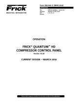
5. Loosen the four screws located on the display plate as
shown in detail A that follows.
6. Once all four screws have been loosened, carefully slide
the display out of the slotted mounting holes.
7. Remove the four screws and washers located at the
sides of the display.
8. Reinstall the new display by reversing steps 7 and 6, in
that order. Use the tool marks left by the hardware to
position the new display.
9. Reinstall the display plate back into position on the panel
door, and loosely reinstall the six hex nuts, do not tighten
yet.
10. Carefully reconnect the display and backlight connectors
on the back of the display.
11. Look at the display from the front of the panel door. Ensure
that the display is centered in the display opening. Once
centered, tighten the six nuts. Re-centering the display
may be necessary after these steps have been completed.
12. Verify the Q5 Processor Board Display jumper settings per
the table shown at the bottom of this page.
A
DE
TAIL A
Display Mounting Plate
Display
INSTALL WA
SHER BETWEEN
DISPLAY AND MOUNTING
PLATE TO HELP WITH
DISPLAY VIBRATION
090.040-LD0001.eps
Figure 1. LCD Display Assembly & Mounting
Table 1. Q5 Processor Board Display Jumpers
Q5 MOTHERBOARD DISPLAY JUMPERS (LINKS)
Jumper Title Function Jumper Setting
CN1000
(LCD
Resolution
Selector)
18-bit
1024x768
(default)
6
4
2
5
3
1
3-5 Closed
&
2-4 Closed
JLVDS2
(Backlight
Level
Selector)
0– 5V
(default)
1
2
3
2-3 Closed
JLVDS3
(Backlight
Control
Mode)
PWM
Mode
(default)
1
2
3
2-3 Closed
(Refer to Section 5 for location of jumpers)
090.040-TB0001.indd
QUANTUM™ HD OPERATOR INTERFACE

QUANTUM™ HD COMPRESSOR CONTROL PANEL
MAINTENANCE
090.040-M (NOV 2016)
Page 11
TOUCHSCREEN DESCRIPTION
The Quantum™ HD utilizes an 8-wire resistive touchscreen
interface to facilitate operator interaction. It consists of a
transparent sheet of glass, which covers the entire display
area, and has numerous rows and columns of micro wires
embedded into its surface. Touching anywhere on the glass
will cause an adjacent row and column of these micro wires
to sense the pressure, and signals the control electronics
that a connection has occurred, and converts the signal to
a cursor location. The action is very similar to the way a
computer mouse would be utilized, in that manipulating a
mouse moves a cursor around on the screen, but in the case
of a touchscreen, a nger tip causes the cursor to move.
The touchscreen allows the operator to simply touch active
areas of the display for the purpose of changing setpoints,
selecting menus, and accessing other operational features.
TOUCHSCREEN CALIBRATION
For the touchscreen to be used reliably, it must be accurately
calibrated. The symptom of an improperly calibrated screen
would be that an area of the screen that the user is touching
is not being recognized, or an adjacent picture element is
being activated instead of the intended one. It is also advis-
able to perform a calibration at unit commissioning.
There are two methods that may be used to access the
Calibration feature:
1. As the Quantum™ HD is powering up, a prompt will appear
for 5 seconds, allowing access to the Screen Calibration
feature.
2. After the Quantum™ HD has been booted, the Screen
Calibration feautre may be accessed by logging into the
service level, then press [Menu]. Once the Menu ap-
pears, press [Service]. After the Service screen appears,
locate the tab that is labled [Calibrate Touch Screen]
and select it.
The display screen will be replaced with an all white screen.
The upper left hand corner of the screen will show a red dot
inside of an animated blue circle with arrows pointing to the
center, as shown here:
The blue circle repeatedly shrinks and grows, to call atten-
tion to the red dot inside. Press as close as possible to the
red dot. After the touchscreen has detected the depression,
the animated circle will move to its next calibration point.
Simply follow the circle, depressing at the red dot in each
new location that it moves to. There will be a total of sixteen
calibration points that will need dened. Upon successfully
dening each point, the screen will return to the home screen.
Screen calibration is complete.
USING AN EXTERNAL USB STYLE
KEYBOARD OR MOUSE
NOTICE
Always be aware of the presence of live AC voltage
within the control enclosure!
TO USE A USB COMPATIBLE COMPUTER KEYBOARD:
Open the control panel door, then use the following
instructions:
Locate the two USB connections on the Q5 Processor Board,
and plug the USB end of the keyboard cable into either one.
The external USB based keyboard is now active and ready
to use. To navigate using the external USB style keyboard
using keyboard mapping, refer to the following chart for
special functions:
Table 2. Keyboard Mapping
Keyboard Key Function
F2 Screen Calibration
F3 Stop Load
F4 Stop Unload
F5 Home
F7 Load
F8 Start Compressor
F9 Unload
F11 Alarm Silence
F12 Stop Compressor
090.040-TB0002.indd
TO USE A USB COMPATIBLE COMPUTER MOUSE:
If using a mouse, note that by moving it, the on-screen cursor
will track it’s movement. Simply navigate the cursor using
the mouse to simulate a nger tip. Click on the screen areas
that you wish to access by pressing the left hand mouse
button. Use the on-screen data and keyboard entry boxes
that appear to enter values and text.
FOR QUANTUM™ HD PANELS WITH KEYPAD
When the Quantum™ HD was rst introduced, and for sev-
eral years afterward, the front panel Touchscreen overlay
included a keypad below the display. The keypad portion of
this overlay has been eliminated in current models. In the
event that a new Touchscreen overlay would need to be
ordered, a eld replacement kit has been provided. The part
number for this kit is 649D6101G01 (SAP #1032704). This
kit comes with replacement instructions and spacers that
allow the new ovelay to be aligned properly with the cutout
opening in the panel door.

QUANTUM™ HD COMPRESSOR CONTROL PANEL
MAINTENANCE
090.040-M (NOV 2016)
Page 12
NOTES

QUANTUM™ HD COMPRESSOR CONTROL PANEL
MAINTENANCE
090.040-M (NOV 2016)
Page 13
090.040-PH0003.tif
SECTION 3 -
Q5 PROCESSOR BOARD & INTERFACE

QUANTUM™ HD COMPRESSOR CONTROL PANEL
MAINTENANCE
090.040-M (NOV 2016)
Page 14
INTRODUCTION
Frick® Controls has released the latest version of the
Quantum ™ HD Control System. The micro-processor is the
brains of the system and is referred to as the Q5 Processor
Board. A photo of this board appears here:
Figure 2. Q5 Processor Board Photo
090.040-PH0004.tif
FEATURES
The Q5 Processor Board includes the following features:
• 6 total USB ports (4 are dedicated, 2 are available)
• 10/100/1000 Mbps Ethernet Connection
• 2 RS-422 ports
• 2 RS-485 ports
• External Video monitor connection
• LED indicators to verify proper operation of various on
board areas (power, communications, Ethernet connec-
tivity, etc.)
• 2 GB RAM memory
• Battery to maintain date and time
WHAT SHOULD OCCUR WHEN
APPLYING POWER
When powering up, the following sequence of events are
indicative of a properly working main processor board:
• The six LED’s in the lower left corner should turn on solid.
• The on-board “buzzer” should “beep” once.
• The display should show several DOS (text) style screens.
A status bar will appear at the bottom of the screen and
displays Fedora 15 as the boot sequence progresses.
• A Windows style screen with the letters HD will appear.
The Operating Status (Home) screen will appear.
• A Loading bar will appear at the bottom of the screen,
showing the percent of load that has completed, this is
followed by additional DOS style text.
After the Q5 Processor Board has properly powered up, the
following sequence of events is indicative of proper com-
munication to the analog and digital boards:
• The Analog and Digital I/O boards TX/RX lights should be
blinking.
• Each I/O board should have the power LED lighted and
the Active LED should be blinking.
• The rst thing that should be checked when troubleshoot-
ing the Q5 Processor Board is its powering up sequence.
WHAT IF THE OPERATING
STATUS SCREEN IS NOT SHOWN
If the Operating Status screen is not shown, check the
following items:
1. If no LED’s are lit, then check AC and DC power. Refer to
the Power Supply section.
2. Check if the lighting of the LED’s is occurring as
described in the What Should Occur When Applying
Powering section.
• If the powering up sequence continues to repeat with-
out displaying the Operating Status screen, then there
is a booting problem.
3. Check all plugged connectors for proper seating.
4. Check if an error message is displayed when booting.
• Be sure to write down any error messages exactly as
they appear, as well as the top line on the screen where
the message appears.
5. Check that the software is OK:
• Is the correct software installed?
• Did you just install new software?
6. Check the display. If the Q5 Processor Board is booting
but you have no display, check the following:
• Check the LED backlight sticks. Look very closely at
the display to see if anything is visible on the screen.
If only a portion looks darkened, it may be that one of
the backlights has failed. If the entire screen is dark
(and it is not is sleep mode), use a beam type source
of good lighting, such as a ashlight, look for any ghost
type image. If it appears that there is something on the
screen but very dark, the problem may be with either
the backlight harness, the display or the Q5 Processor
Board. Check to ensure that both ends of the backlight
harness is plugged in securely. There is a sticker on the
display mounting plate, that will have a part number
that describes the type of display.
• Verify that both the display cable and the backlight
cable are rmly seated. It may be necessary to remove
Q5 PROCESSOR BOARD

QUANTUM™ HD COMPRESSOR CONTROL PANEL
MAINTENANCE
090.040-M (NOV 2016)
Page 15
the video cable from the back of the LCD display and
re-seat it to be sure it is connected properly.
WARNING
This is a small connector. Caution should be observed
so that it is not damaged due to excessive force.
• Refer to the Operator Interface section and check
that the LCD, LCD cable, and software versions are
matched correctly.
BATTERY FUNCTION AND REPLACEMENT
The Q5 Processor Board utilizes a battery to maintain cor-
rect date and time for the purpose of stamping warnings
and shutdowns with the date and time that they occurred.
If the date and time are not being maintained properly, this
may indicate that the battery is not functioning, and should
be replaced. The battery may be ordered through Baltimore
Parts (P/N 333Q0001786) or may be purchased at most
electronic shops (manufacturers P/N CR-2032).
The battery is fully assessable, but is surrounded by sensi-
tive electronic components, so care should be taken when
changing.
To replace the battery, ensure that the Control Power switch
has been turned OFF.
Locate the Battery socket, as shown on the following drawing:
Once a static wrist band is properly donned, place your n-
gernail under the edge of the battery, and gently lift up. The
battery should release itself from the socket easily. Take a
new battery and place it into the holder in the same orien-
tation as the old battery (the side with the writing must be
facing out). Return the Control Power switch back to ON.
Once the Q5 Processor Board has rebooted, the correct Date
and Time must be set.
INTERFACE BOARD DESCRIPTION
An interface board has been developed by Frick controls
allowing the user to interface external serial communications
connections to the Q5 Processor Board.
These connections consist of:
• Comm 1 (RS-422/485)
• Comm 2 (RS-422/485)
• Comm 3 (RS-485)
A photo of this interface board is shown here:
Figure 3. Interface Board Photo
090.040-PH0005.tif

QUANTUM™ HD COMPRESSOR CONTROL PANEL
MAINTENANCE
090.040-M (NOV 2016)
Page 16
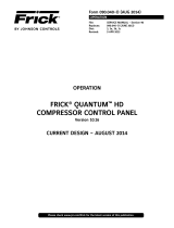
NOTE 1: The triangle symbol (
) denotes Pin 1 on connectors. Refer to the chart on the following page for
jumper settings.
NOTE 2: Do NOT remove the CN4 jumper. Removal of this jumper will cause the processor to not power up.
NOTE 3: Although the Q5 Processor Board is the main controller, most of customer connections will be to the Interface board,
as shown later.
CN1
Ethernet
Connector
CN_POWER1
Power
Connector
USB
Ports
Ethernet
LED’s
JLVDS3
JLVDS2
CMOS1
CN3
INVERTER1
Inverter
Connector
Flash Card
located under
the board
here
CN1000
PO
WER
LED’s
DIMM1
USB
Ports
LVDS1
Display
Connector
COM2
RS-422/
485
COM1
RS-422/
485
COM4
RS-485
COM3
RS-485
CRT1
Video
Monitor
BH1
Battery
FUSE
090.040-WD0001.eps
Figure 4. Q5 Processor Board Diagram

QUANTUM™ HD COMPRESSOR CONTROL PANEL
MAINTENANCE
090.040-M (NOV 2016)
Page 17
Q5 PROCESSOR BOARD JUMPERS, LED’S AND CONNECTORS
JUMPER
TITLE FUNCTION JUMPER SETTING JUMPER
TITLE FUNCTION JUMPER SETTING
CMOS1
(CMOS Clear)
Normal
(default)
1 2 3
1 - 2 Closed CN3
(Touch Panel
Type
Selector)
5-Wire Touch
Screen
1 2 3
1-2 Closed
Clear CMOS
1 2 3
2 - 3 Closed
8-Wire Touch
Screen
(default)
1 2 3
2-3 Closed
CN1000 (LCD
Resolution
Selector)
24-bit
800x600
6
4
2
5
3
1
1-3 Closed &
2-4 Closed JLVDS2
(Backlight
Level
Selector)
0– 5V
(default)
1
2
3
2-3 Closed
24-bit
1024x768
(default)
6
4
2
5
3
1
3-5 Closed
&
2-4 Closed
0 – 2.5V
1
2
3
1-2 Closed
18-bit 800x600
6
4
2
5
3
1
1-3 Closed
&
4-6 Closed JLVDS3
(Backlight
Control
Mode)
Voltage Mode
1 2 3
1-2 Closed
18-bit 640x480
6
4
2
5
3
1
3-5 Closed
&
4-6 Closed
PWM Mode
(Pulse Width
Modulation)
(default)
1 2 3
2-3 Closed
NOTE 1:
The triangle symbol (
) denotes Pin 1 on connectors.
NOTE 2:
Jumper CN4 is not shown on this chart, as it must always be installed.
090.040-TB0003.indd
CONNECTOR PINOUT TABLE
Connector
Title Pin Function
CN_PWR1
(Power
Input)
1 Ground (GND)
2 Ground (GND)
3 VCC 12V
4 VCC 12V
090.040-TB0005.indd
LED DEFINITION TABLE
LED Title Label Color Function
Power LED’s
LED1 Red 5VSB
LED2 Red 3VSB
LED3 Green VCC 12V
LED4 Green VCC 5V
LED5 Green VCC 3V
LED6 Blue Power On OK Status
CN1000
(LCD
Resolution
Selector)
1000MB Green Giga – LAN Speed
100MB Yellow 100MB - LAN Speed
10MB Red 10MB –LAN Speed
ACT Green
(Blinks) LINK Activity
090.040-TB0004.indd
Table 3. Q5 Board Jumper Settings
Table 4. Q5 Board LED Denitions Table 5. Q5 Board Connector Pinouts

QUANTUM™ HD COMPRESSOR CONTROL PANEL
MAINTENANCE
090.040-M (NOV 2016)
Page 18
Jumper JP1 Function Jumper Setting
1 - 2 Not Used Not Installed
3 - 4 Reformat E2Prom Installed
5 - 6 Erase Setpoints (at boot-up) Installed
7 - 8 Not Used Not Installed
9 - 10 Disable Watchdog Installed
090.040-TB0006.indd
(Comms 3 and 4 have no jumpers)
Comm 1 Comm 2 Function Jumper Setting
J1 J7
RS-422 (4-Wire)
Default 1 - 2 Closed
RS-485 (2-Wire) 2 - 3 Closed
J2 J13 Pull Down Default 1 Pin Only
J3 J16 Pull Up Default 1 Pin Only
J5 J17
RS-422 Default 1 Pin Only
RS-485 1 - 2 Closed
J6 J18
RS-422 Default 1 Pin Only
RS-485 1 - 2 Closed
J4 J22 High Speed Target
Default 1 - 2 Closed
NOTE: The triangle symbol ( ) denotes Pin 1 on connectors.
3
2
1
3
2
1
090.040-TB0007.indd
Do Not
Remove J14
Touch-
screen
connecto
r
P1
Power Connector
Baud Rate Jumpers
J15 Not Installed = 19200 (Default)
J15 Pins 1-2 Installed = 38400
J15 Pins 3-4 Installed = 56K
J15 Pins 1-2 and 3-4 Installed = 115K
COMM
4
COMM
3
COMM
2
COMM
1
JP1
090.040-WD0002.eps
Figure 5. Interface Board Diagram
COMMS 1-4 PINOUTS AND JUMPER LOCATIONS
COMM-1
(P10)
RS-422
GND
+TX
-TX
+RX
-RX
RS-485
GND
N/C
N/C
+TX/+RX
-TX/-RX
COMM-2
(P11)
RS-422
GND
+TX
-TX
+RX
-RX
RS-485
GND
N/C
N/C
+TX/+RX
-TX/-RX
COMM-4
(P17)
RS-485
(RESERVED)
COMM-3
(P16)
RS-485
GND
+TX/+RX
-TX/-RX
090.040-WD0003.eps
Figure 6. Pinouts and Jumper Locations
Table 6. JP1 System Settings
Table 7. Comms 1 & 2 Jumper Settings

QUANTUM™ HD COMPRESSOR CONTROL PANEL
MAINTENANCE
090.040-M (NOV 2016)
Page 19
The pictorial below depicts the Q5 Processor Board, and the necessary interconnects between it and the Interface board. Each
of the interconnecting harnesses must be installed as shown for proper operation.
090.040-WD0004.eps
Figure 7. Q5 Processor Board Interconnections

QUANTUM™ HD COMPRESSOR CONTROL PANEL
MAINTENANCE
090.040-M (NOV 2016)
Page 20
The following pictorial shows the locations of the Q5 Processor Board and the Interface board and how they mount to the back of the
display plate.
Display Plate
Interface Boar
d
Q5 Processor Board
090.040-WD0005.eps
Figure 8. Q5 Processor Board Mounting
/