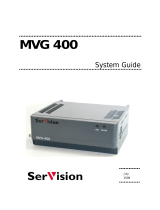
Kathrein MVG 10 User manual

Type
User manual

This manual is also suitable for

Kathrein MVG 10 is a fully equipped video sweep generator designed to selectively sweep and measure the forward and return paths of television cable installations without interfering with the connected subscribers. The MVG 10 is suitable for measuring the return path - terminal outlet to head-end - in the frequency range 4.0 MHz…80 MHz. The device can generate a sweep in several partial frequency ranges, which helps avoid interrupting the TV reception by leaving out the ranges that are in use.

Kathrein MVG 10 is a fully equipped video sweep generator designed to selectively sweep and measure the forward and return paths of television cable installations without interfering with the connected subscribers. The MVG 10 is suitable for measuring the return path - terminal outlet to head-end - in the frequency range 4.0 MHz…80 MHz. The device can generate a sweep in several partial frequency ranges, which helps avoid interrupting the TV reception by leaving out the ranges that are in use.

Operator's manual
Video Sweep Generator
MVG 10
Order no.: 208 320
2
Preface
3
Preface
Dear customer,
This handbook aims to help you use the various functions of the MVG10 in
the optimal manner. Please pay attention to all instructions. Kathrein-Werke
KG has made every effort to ensure the information and descriptions are
correct and complete.
We reserve the right to make changes to this handbook without prior notice.
In particular, this applies to changes made due to technical advancements.
We are always grateful to receive your comments and suggestions for
improvement.
Prior written consent from Kathrein-Werke KG is required for publishing,
copying, reprinting or electronically reproducing this handbook or parts
thereof.
All product names and trademarks in this handbook are the property of the
respective companies.
Please read the safety notes carefully!
Yours,
The KATHREIN team
Customer service
Please send the unit to the following address in case of defect or for
calibration:
Fa. ESC
Kathrein-Zentralkundendienst
Bahnhofstraße 108
83224 Grassau
Germany
Tel.: +49 8641 9545-25
Fax: +49 8641 9545-35
4
Contents
5
Contents
Preface .....................................................................................................................................................3
Contents ...................................................................................................................................................5
Safety notes..............................................................................................................................................6
Safety notes..............................................................................................................................................7
System description and usage .................................................................................................................8
Views, connections and controls ........................................................................................................... 11
Button functions..................................................................................................................................... 12
System settings ..................................................................................................................................... 13
Noise generator ..................................................................................................................................... 15
Signal generator .................................................................................................................................... 16
Sweep generator ................................................................................................................................... 18
Channel sweep generator ..................................................................................................................... 22
Recall..................................................................................................................................................... 26
Technical appendix................................................................................................................................ 27
Safety notes
6
Safety notes
Validity of handbook
This handbook is valid for MVG 10, order no.: 208 320.
The following notes are important for operating the MVG 10 and
should be observed under all circumstances.
General safety notes
The MVG 10 was developed and produced in compliance with
the relevant harmonised guidelines, standards and additional
technical specifications. The product is state-of-the-art and
ensures the maximum level of safety.
However, this safety level can only be reached in practice if all
of the necessary measures are taken and is subject to the care
taken by the operator.
Symbols used
The following symbols are used in this operator's manual.
The main aim of these symbols is to bring the user's attention to
the text opposite the respective symbol.
Danger! Live component!
This symbol indicates danger to life and health.
Attention!
This symbol indicates that particular attention must be paid to
this section of the manual.
Example
This symbol indicates an example of the measurement function
being explained.
Safety notes
7
Safety notes
Always observe the VDE safety regulations.
Observe the maximum permissible signal feed-in level.
Neither DC voltage nor low-frequency AC voltage may be applied
to the RF port.
Only use fuses with the same cut-out characteristics.
The unit is live even when not connected.
The unit may only be operated with all shielding covers fitted and
when closed to prevent electromagnetic interference. Only use
suitable shielded cable.
Improper use during mains operation is a risk to life!
Connections
Improperly connected connections can lead to operating faults or
defects in the unit.
Use in accordance with intended purpose
The operator must ensure that
the measuring instrument is only used in accordance with its intended
purpose.
the measuring instrument is only used when in good order and fully
functional.
the safety and warning notes on the measuring instrument are not
removed and remain legible.
Mechanical durability
The MVG 10 is designed for mobile usage and the mechanical
demands associated with this. The MVG 10 should not be exposed to
heavy mechanical stress such as being struck, knocked or dropped as
this can cause damage to the unit.
Electronic equipment must not be disposed of in domestic waste.
According to directive 2002/96/EC OF THE EUROPEAN
PARLIAMENT AND COUNCIL of 27 January 2003 on waste electrical
and electronic equipment, it must be disposed of professionally.
Please take this unit to a public collection point intended for this type
of disposal at the end of its useful life.
System description and usage
8
System description and usage
The MVG 10 Video Sweep Generator is designed to selectively sweep
and measure the forward path and return path of television cable
installations without interfering with the connected subscribers. The
required sweep ranges, channels and signal levels (36…100 dBµV)
can be programmed step-by-step. The channels can be set to various
standards (e.g. B/G etc.).
Frequency ranges that are in use must be left out so that the
subscriber reception is not disrupted.
Make a frequency and signal level plan before performing the
measurement!
Before each frequency change, the MVG 10 transmits the next
reception frequency to the MSK 33 with a telemetric signal. In ranges
that are in use and which may not be sweeped, the MSK 33 can, as
an option, continue measurement in the same channel plan at
maximum scan speed. The MVG 10 pauses during this period.
The MSK measures the signal levels transmitted and presents them in
the spectrum. The measurement can also be printed out with the
integrated printer.
Measurement principle
MVG10 MSK33
Message FRQa+1
FRQa FRQa
Transmission
range Recording
Message FRQy
FRQx FRQx
Transmission-free quick
range sweep
Message FRQz
FRQy FRQy
Transmission
range Recording
Message FRQa
FRQz FRQz
Return path measurement
The MVG 10 is also suitable for measuring the return path – terminal
outlet to head-end – in the frequency range 4.0 MHz…80MHz.
For this, the MSK 33 must be equipped with the return path option.
The MVG 10 Video Sweep Generator must be modulated with a video
signal.
Although measurement can be performed in cables that are in use,
the ranges that are in use may not be sweeped. In addition, the
MVG 10 signal generator can sweep in several partial ranges i.e.
ranges that are in use can be left out by the sweep generator so that
TV reception is not interrupted. The MVG 10 sweep generator informs
the MSK 33 of the next respective reception frequency over the RF
channel.
System description and usage
9
Downstream measurement: 47…860 MHz
Head-end (or transfer point) Transfer point (or terminal outlet)
Cable installation
with return path-capable amplifiers
Upstream measurement: 4.0…80 MHz
Head-end (or transfer point) Transfer point (or terminal outlet)
Cable installation
with return path-capable amplifiers
Comfortable upstream 4.0…80 MHz and
Downstream 47…860 MHz measurement
Cable installation
with return path-capable
amplifiers
ext CVBS
Graphics RGB
Presentation of upstream spectrum at head-end
Measurement of downstream spectrum
Upstream measurement:
The MVG 10 (1) sweeps the return path in the free frequency ranges.
The MSK 33 (1) receives the signals in MVG 10 – tracking mode.
The graphics from the MSK33 (1) are provided to the MVG10 (2) in
RGB (60 Hz) and transmitted to the MSK33 (2) on a free downstream
channel (attention: double-sideband modulation).
MVG10 (2)
Signal
sweep
generator
MVG10
Sweep
generator (1)
MSK33
receiver (2)
MSK 33
receiver
MVG 10
Sweep
generator
MVG 10
Sweep
generator
MSK 33
receiver
MSK33
receiver (1)
System description and usage
10
The spectrum at the head-end can be printed out from the MSK 33 (1)
using the print command "Prt 999" on the MVG 10 (1).
The command "Clear" clears the spectrum presentation on the
MSK 33 (1).
Downstream measurement:
The MVG 10 (2) is switched from signal generator mode to
downstream sweep generator mode via the MSK 33 (1) using the
command "Fkt A 1" on the MVG 10 (1).
The MVG 10 (2) sweeps the forward path in the free frequency
ranges.
The MSK33 (2) receives the signals in MVG 10 – tracking mode.
The MVG 10 (2) is switched back to signal generator mode with the
command "Fkt A 0" on the MVG 10 (1). This is performed via the
turn-on voltage of the SCART line.
Uscart = 12 V effects recall no. 1 on MVG 10.
Uscart = 0 V effects recall no. 0 on MVG 10.
Views, connections and controls
11
Views, connections and controls
Left-hand side
Scart socket
Right-hand side
RS232 socket Power supply
Frontal view
RF output Display Keypad
Button functions
12
Button functions
The following information explains the operation of the MVG 10.
Please use the illustration of the operating concept for assistance.
Button Function Display
On
Off
1. Switch on unit when
depressed briefly
The upper display appears first,
then the lower display with the
last function that was set
2. Switch off unit when
depressed for an extended
period
Menu
Select
Confirm selected main or subfunction (see below)
Select main and subfunctions
Example: Setting Sys Backlight (display backlight).
T
Press button until "System…" appears in the display,
Menu
then press
, Sys FactSetup is displayed.
Select
T
Use
to set to Sys Backlight and
W X
use
to switch backlight on/off.
- +
W X
- +
Set frequency, channel and signal level values
0 9
Numerical entry of frequency, channel and signal level values
·
S-Ch
Preselection button for special channels
·
Example: Set special channel 25 =
S-Ch 2 5
"Enter" button for confirming numerical entries
KATHREIN MVG10
NG Store
nr: 0
System settings
13
System settings
We recommend checking the factory settings before initial start-up.
Please use the operating concept on page 2 for help with
understanding the operating sequence.
Function Button actuation Display
Switch on unit when depressed
briefly
The upper display appears first,
then the lower display shortly
afterwards with the last function
that was set
On
Off
Select "System" main function
and
show battery charge state
Confirm selected function
Call up factory settings with
"Enter"
Menu
Select
Switches to display:
Reselect "System" main
function
Menu
Select
Display backlight
on/off
W X
- +
Display system software
version
Display serial number
System...
Accu 100 %
Sys SeriesNr.
XXX
KATHREIN MVG10
NG Store
nr: 0
Sys FactSetup
Sys FactSetup
restored
Recall
nr: 0
Sys Backlight
on/off
Sys Software
V1.3x 30.05.01
Sys FactSetup
System settings
14
Display units
W X
+
- +
System baud rate
setting not possible
Transmission readiness
setting not possible
Confirm entries
Menu
Select
System..
Accu 100 %
Sys Unit
dBµV (dBmv, dBm)
Sys RTS/CTS
on
Sys Baudr: 19.2k
Noise generator
15
Noise generator
The noise generator is used for measuring cable installations or
sections of cable installations that are not yet occupied with
programming.
It generates a broadband noise to evaluate the frequency response in
the range from 4 MHz to 1 GHz. The bandwidth can be set to 1 MHz
or 7/8 MHz.
Do not use the noise generator if programmes or services are fed
into the cable network and/or if subscribers are connected!
Please use the operating concept on page 2 for help with
understanding the operating sequence.
Function Button actuation Display
Switch on unit when depressed
briefly
The upper display appears first,
then the lower display shortly
afterwards with the last function
that was set
On
Off
Select the "Noise generator"
main function
Show battery charge state
Confirm selected function
Show last signal level set
Menu
Select
Set signal level
W X
- +
Enter signal level directly
followed by "Enter"
or
0 9
see above
Set bandwidth
1 MHz or 7/8 MHz
W X
+
- +
Store settings in memory at
addresses 0 to 9
Confirm entries
Menu
Select
NoiseGenerator..
Accu 100 %
NG Level
XX.X dBµV
NG Bandwidth
1 MHz (7/8 MHz)
NG Store
Nr: 0
NoiseGenerator..
Accu 100 %
KATHREIN MVG10
NG Store
nr: 0
NG Level
60.0 dBµV
Signal generator
16
Signal generator
The signal generator is needed to transmit test signals and the screen
view from the MSK 33 during "Comfortable Up/Downstream
measurement" (see system description). In addition to an internal test
picture of coloured bars it has an external modulation input
(CVBS/RGB + sound) and is double-sideband modulated.
The channels/frequencies and levels can be selected freely.
Only use the signal generator on free channels so that
programmes and services in the cable network are not
interrupted. Please use the operating concept on page 2 for help
with understanding the operating sequence.
Function Button actuation Display
Switch on unit when depressed
briefly
The upper display appears first,
then the lower display shortly
afterwards with the last function
that was set
On
Off
Select "Signal generator"
main function and
show battery charge state
Confirm selected function
Show last signal level set
Menu
Select
Set signal level
W X
- +
Enter signal level directly
followed by "Enter"
or
0 9
see above
Set transmission frequency
in MHz
W X
+
- +
SignalGenerator..
Accu 100 %
SG Level
XX.X dBµV
SG Frequency
224.25 MHz
KATHREIN MVG10
NG Store
nr: 0
SG Level
60.0 dBµV
Signal generator
17
Enter transmission
frequency directly followed
by "Enter"
Channel frequency inputs with
incorrect entries after the point
are not accepted!
or
0 9
see above
Channel entry -
special channels with press
·
S-Ch
first!
W X
+
- +
Enter channel
number directly special
channels with press
·
S-Ch
first!
Also switch back
to normal channel
entry with
or
0 9
·
S-Ch
see above
Set standards
B/G, D/K, I, M, Mj, H
W X
+
- +
Set modulation
int-AV, ext-CVBS, ext-RGB,
ext-FM, int-FM
W X
+
- +
Store at addresses 0 to 9
W X
+
- +
Confirm entries
SG Store
Nr: 0
SignalGenerator..
Accu 100 %
SG Channel
C __
SG Standard
B/G
SG Modulation
int-AV
Sweep generator
18
Sweep generator
The sweep generator is used to sweep in 10 preset frequency ranges
(measuring profiles). The profiles can be programmed to free ranges
depending on the channel allocation in the cable network, so that
measurement is possible without interrupting or interfering with
programmes. The frequencies and levels can be selected freely.
Only use the sweep generator on free channels so that
programmes and services in the cable network are not
interrupted.
Please use the operating concept on page 2 for help with
understanding the operating sequence.
Function Button actuation Display
Switch on unit when depressed
briefly
The upper display appears first,
then the lower display shortly
afterwards with the last function
that was set
On
Off
Select "Sweep generator"
main function and
show battery charge state
Confirm selected main function
Show last level set
Menu
Select
Set signal level
W X
- +
Enter signal level directly
plus "Enter"
or
0 9
see above
Enter number of measuring
profile to be pre-programmed,
0 to 9
Incorrect entries are not
accepted.
W X
+
- +
Enter profile directly
plus "Enter"
Incorrect entries are not
accepted!
or
0 9
see above
SweepGenerator..
Accu 100 %
SwG FreqRange
Nr: X
KATHREIN MVG10
NG Store
nr: 0
SwG Level
60.0 dBµV
SwG Level
XX.X dBµV
Sweep generator
19
Enter start frequency
W X
+
- +
Enter frequency directly
or
0 9
see above
Enter end frequency
W X
+
- +
Enter frequency directly
or
0 9
see above
50-kHz steps from one
frequency to next in MHz
W X
+
- +
Enter frequency directly
or
0 9
see above
Step duration from one
frequency to next in ms
(150 ms – 2500 ms)
W X
+
- +
Enter time directly
or
0 9
see above
Tracking on/off
Switch sequential control
of MSK 33 on/off
No other analysers
can be controlled.
W X
+
- +
Select pre-programmed
measuring profiles (0…9) by
entering numbers without space
followed by "Enter" – the
sequence is started and can
be tracked on the MSK 33.
W X
+ + +
- + 09
SwG Tracking
on/off
SwG SelRange
123....... no run/run
SwG FreqRange X
Start XXX.XX MHz
SwG FreqRange X
Stop XXX.XX MHz
SwG FreqRange X
Step X.XX MHz
SwG FreqRange X
XXX ms
Sweep generator
20
Clear screen presentation on
MSK 33 with "Enter"
X
+ +
+
Command to clear spectrum
received by MSK33
(MVG10 tracking)
Enter control printout number
(up to 3 digits), confirm with
"Enter" and run with "Enter"
X
+ +
+ 0…..9
Command to switch a second
MVG10 to stored position
"Recall 0" via MSK33
(MSK33 and MVG10
connected via SCART)
X
+
Command to switch a second
MVG10 to stored position
"Recall 1" via MSK33
(MSK33 and MVG10
connected via SCART)
X
+
Command to switch the
MSK33 video signal from
internal graphics to ext. CVBS.
The respective signals are
relayed to the MVG10 via the
SCART socket for modulation.
X
+
Command to switch the
MSK33 video signal from
ext. CVBS to internal graphics.
The respective signals are
relayed to the MVG10 via the
SCART socket for modulation.
X
+
Store settings in memory at
addresses 0 to 9
Confirm entries
SwG ControlData
Clear no run
SwG ControlData
Clear no run/run
SwG ControlData
Prt XXX no run
SwG ControlData
Fkt A 0 no run
SwG ControlData
Fkt A 1 no run
SwG ControlData
Fkt B 1 no run
SwG ControlData
Fkt B 0 no run
SwG Store
nr: 0
ChannelSweep...
Accu 100 %
  • Page 1 1
  • Page 2 2
  • Page 3 3
  • Page 4 4
  • Page 5 5
  • Page 6 6
  • Page 7 7
  • Page 8 8
  • Page 9 9
  • Page 10 10
  • Page 11 11
  • Page 12 12
  • Page 13 13
  • Page 14 14
  • Page 15 15
  • Page 16 16
  • Page 17 17
  • Page 18 18
  • Page 19 19
  • Page 20 20
  • Page 21 21
  • Page 22 22
  • Page 23 23
  • Page 24 24
  • Page 25 25
  • Page 26 26
  • Page 27 27
  • Page 28 28

Kathrein MVG 10 User manual

Type
User manual
This manual is also suitable for

Kathrein MVG 10 is a fully equipped video sweep generator designed to selectively sweep and measure the forward and return paths of television cable installations without interfering with the connected subscribers. The MVG 10 is suitable for measuring the return path - terminal outlet to head-end - in the frequency range 4.0 MHz…80 MHz. The device can generate a sweep in several partial frequency ranges, which helps avoid interrupting the TV reception by leaving out the ranges that are in use.

Ask a question and I''ll find the answer in the document

Finding information in a document is now easier with AI