
SATEL-TR49 SnapOn
TRANSCEIVER MODULE
INTEGRATION GUIDE
Version 1.7

SATEL-TR49 SnapOn
Integration Guide, Version 1.7
1
IMPORTANT NOTICE
All rights to this manual are owned solely by SATEL Oy (referred to in this user guide as SATEL).
All rights reserved. The copying of this manual (without the written permission from the owner) by
printing, copying, recording or by any other means, or the full or partial translation of the manual
to any other language, including all programming languages, using any electrical, mechanical,
magnetic, optical, manual or other methods or devices is forbidden.
SATEL reserves the right to change the technical specifications or functions of its products, or to
discontinue the manufacture of any of its products or to discontinue the support of any of its
products, without any written announcement and urges its customers to ensure, that the
information at their disposal is valid.
SATEL software and programs are delivered ”as is”. The manufacturer does not grant any kind of
warranty including guarantees on suitability and applicability to a certain application. Under no
circumstances is the manufacturer or the developer of a program responsible for any possible
damages caused by the use of a program. The names of the programs as well as all copyrights
relating to the programs are the sole property of SATEL. Any transfer, licensing to a third party,
leasing, renting, transportation, copying, editing, translating, modifying into another programming
language or reverse engineering for any intent is forbidden without the written consent of SATEL.
SATEL PRODUCTS HAVE NOT BEEN DESIGNED, INTENDED NOR INSPECTED TO BE USED IN
ANY LIFE SUPPORT RELATED DEVICE OR SYSTEM RELATED FUNCTION NOR AS A PART OF
ANY OTHER CRITICAL SYSTEM AND ARE GRANTED NO FUNCTIONAL WARRANTY IF THEY
ARE USED IN ANY OF THE APPLICATIONS MENTIONED.
Salo, FINLAND 2019
Copyright: 2019 SATEL Oy
No part of this document may be reproduced, transmitted or stored in a retrieval system in any form or by any means without the
prior written permission of SATEL Oy.

SATEL-TR49 SnapOn
Integration Guide, Version 1.7
2
RESTRICTIONS ON USE – SATEL-TR49 SnapOn
SATEL-TR49 SnapOn radio transceiver module has been designed to operate on 410-475 MHz
and 902-928 MHz, the exact use of which differs from one region and/or country to another. The
user of a radio transceiver module must take care that the said device is not operated without the
permission of the local authorities on frequencies other than those specifically reserved and
intended for use without a specific permit.
SATEL-TR49 SnapOn operating on 410-475 MHz band is allowed to be used in the following
countries, either on license free channels or on channels where the operation requires a license.
More detailed information is available at the local frequency management authority.
Countries: AT, BE, BG, CA, CH, CY, CZ, DE, DK, EE, ES, FI, FR, GB, GR, HU, IE, IS, IT, LT, LU,
LV, MT, NL, NO, PL, PT, RU, RO, SE, SI, SK, US.
This integration guide applies to the combination of Firmware/Hardware version listed in the
table below. See www.satel.com for the newest firmware and Integration Guide version.
Firmware version
Hardware version
Note!
07.45.2.3.2.11
SPL0061a
First official release
WARNING - RF Exposure
To comply with RF exposure compliance requirements, maximum antenna gain (in dB) must not
exceed calculated signal loss (in dB) in antenna cable and separation distance of at least 25
cm must be maintained between the antenna of this device and all persons. This device must
not be co-located or operating in conjunction with any other antenna or transmitter.

SATEL-TR49 SnapOn
Integration Guide, Version 1.7
3
RESTRICTIONS ON USE – SATEL-TR49 SnapOn
SATEL-TR49 SnapOn operating on 902-928 MHz band is allowed to be used in the following
countries. More detailed information is available at the local frequency management authority.
Countries: CA and US.
This radio transmitter 2422A-SATELTA37 has been approved by Industry Canada to operate with
the antenna types listed below with the maximum permissible gain indicated. Antenna types not
included in this list, having a gain greater than the maximum gain indicated for that type, are
strictly prohibited for use with this device.
Antenna type
Manufacturer
Antenna model
Maximum gain (dBi)
Omnidirectional
Oy CompleTech Ltd
CA915H-TNC_A
0
Directional (yagi)
Oy CompleTech Ltd
CA930Y
6
NOTE!
According to the requirements of the FCC, the integrator should make sure that the SATELLINE-
M3-TR49 is compliant to part 15C while integrated in the host device. Output power and
spurious emissions should be verified.
WARNING - RF Exposure
To satisfy FCC and ISED RF exposure requirements for mobile transmitting devices, a
separation distance of 25 cm or more should be maintained between antenna of this device
and persons during device operation. To ensure compliance, operations at closer than this
distance is not recommended. The antenna used for this transmitter must not be co-located in
conjunction with any other antenna or transmitter. FCC regulations allow up to 36 dBm
equivalent isotropically radiated power (EIRP). Therefore, the sum of the transmitted power (in
dBm), the cabling loss and the antenna gain cannot exceed 36 dBm.

SATEL-TR49 SnapOn
Integration Guide, Version 1.7
4
PRODUCT CONFORMITY
Hereby, SATEL Oy declares that SATEL-TR49 SnapOn radio transceiver module is in compliance
with the essential requirements (radio performance, electromagnetic compatibility and electrical
safety) and other relevant provisions of Directive 2014/53/EU. Therefore the equipment is labeled
with the following CE-marking.
For 902-928 MHz only:
This device complies with Industry Canada license-exempt RSS standard(s) and part 15 of the
FCC Rules. Operation is subject to the following two conditions: (1) this device may not cause
interference, and (2) this device must accept any interference, including interference that may
cause undesired operation of the device. Changes or modifications not expressly approved by
the party responsible for compliance could void the user's authority to operate the equipment.
Le présent appareil est conforme aux CNR d'Industrie Canada applicables aux appareils radio
exempts de licence. L'exploitation est autorisée aux deux conditions suivantes : (1) l'appareil ne
doit pas produire de brouillage, et (2) l'appareil doit accepter tout brouillage radioélectrique
subi, même si le brouillage est susceptible d'en compromettre le fonctionnement.

SATEL-TR49 SnapOn
Integration Guide, Version 1.7
5
WARRANTY AND SAFETY INSTRUCTIONS
Read these safety instructions carefully before using the product:
-Warranty will be void, if the product is used in any way that is in contradiction with the instructions
given in this manual
-The radio transceiver module is only to be operated at frequencies allocated by local authorities,
and without exceeding the given maximum allowed output power ratings. SATEL and its distributors
are not responsible, if any products manufactured by it are used in unlawful ways.
-The devices mentioned in this manual are to be used only according to the instructions described
in this manual. Faultless and safe operation of the devices can be guaranteed only if the transport,
storage, operation and handling of the device are appropriate. This also applies to the
maintenance of the products.

SATEL-TR49 SnapOn
Integration Guide, Version 1.7
6
HOST INTEGRATION
To ensure compliance with all non-transmitter functions the host manufacturer is responsible for
ensuring compliance with the module(s) installed and fully operational. For example, if a host
was previously authorized as an unintentional radiator under the Declaration of Conformity
procedure without a transmitter certified module and a module is added, the host manufacturer
is responsible for ensuring that after the module is installed and operational the host continues
to be compliant with the Part 15B unintentional radiator requirements. This module is certified
for Fixed and Mobile Applications only, for Portable applications you will require a new
certification.
This device has been modularly approved. Model name, FCC and Industry Canada identifiers of
this product must appear on the outside label of the end-user equipment.
Host labelling example:
Model Name:
Contains FCC ID:
IC:
This device complies with part 15 of the FCC rules.
Operation is subject to the following two conditions:
(1) This device may not cause harmful interference,
and (2) this device must accept any interference
received, including interference that may cause
undesired operation.

SATEL-TR49 SnapOn
Integration Guide, Version 1.7
7
TABLE OF CONTENTS
IMPORTANT NOTICE ............................................................................................. 1
RESTRICTIONS ON USE – SATEL-TR49 SNAPON ................................................... 2
RESTRICTIONS ON USE – SATEL-TR49 SNAPON ................................................... 3
PRODUCT CONFORMITY ........................................................................................ 4
WARRANTY AND SAFETY INSTRUCTIONS ............................................................. 5
HOST INTEGRATION ............................................................................................. 6
TABLE OF CONTENTS ............................................................................................ 7
1 INTRODUCTION ..................................................................................... 10
1.1 Terms and abbreviations ......................................................................... 10
1.2 Description of the product ....................................................................... 10
2 TECHNICAL SPECIFICATIONS .................................................................. 11
2.1 Absolute maximum ratings ...................................................................... 11
2.2 DC electrical specifications ....................................................................... 11
2.3 Specifications, SATEL-TR49 SnapOn (on 410-475 MHz) .......................... 11
2.4 Specifications, SATEL-TR49 SnapOn (on 902-928 MHz) .......................... 13
3 ELECTRICAL INTERCONNECTION SATEL ................................................. 15
3.1 Pin order of the Mini PCIe interface ........................................................ 15
3.2 LED_WWAN, LED_WLAN and LED_WPAN IO pins .................................... 16
3.3 Wake ........................................................................................................ 16
3.4 USB_D- and USB_D+ IO pins ................................................................... 17
3.5 PERST# ..................................................................................................... 17
3.6 W_Disable................................................................................................. 17

SATEL-TR49 SnapOn
Integration Guide, Version 1.7
8
3.7 +3.3Vaux .................................................................................................. 17
3.8 Antenna interface .................................................................................... 17
4 MECHANICAL CONSIDERATIONS SATEL-TR49 SNAPON ........................ 18
4.1 Dimensions and interfaces ...................................................................... 18
4.2 Dimensions of the Mini PCI Express connector ........................................ 18
4.3 Installing the Mini PCIe Module on the Host device ............................... 19
4.1 Thermal Design Guide ............................................................................. 21
5 OPERATING MODES ............................................................................... 22
5.1 Safe mode ................................................................................................ 22
5.2 Restart ...................................................................................................... 22
6 CHANGING PARAMETERS USING SL COMMANDS ................................ 23
6.1 SL Commands ........................................................................................... 23
6.2 SL Command Mode .................................................................................. 23
7 DEFAULT DELIVERY VALUES – SATEL-TR49 SNAPON (410-475 MHZ) ... 25
8 DEFAULT DELIVERY VALUES – SATEL-TR49 SNAPON (902-928 MHZ) ... 26
9 CONSIDERATIONS .................................................................................. 27
9.1 EMI Interferers ......................................................................................... 27
9.2 Electrostatic discharge ............................................................................. 27
9.3 Using the device in unmanned high reliability applications .................. 28
9.4 Additional improvements for more reliable radio link ........................... 28
10 APPENDIX A (SL COMMANDS, 410-475 MHZ) ....................................... 29
10.1 SL COMMANDS – SATEL-TR49 SnapOn (410-475 MHz) ........................... 29
11 APPENDIX B (SL COMMANDS, 902-928 MHZ) ....................................... 36

SATEL-TR49 SnapOn
Integration Guide, Version 1.7
9
11.1 SL COMMANDS – SATELLINE -TR49-SnapOn, Freewave protocol (902-928
MHz) ........................................................................................................ 36
12 APPENDIX D (IP TRAFFIC) ....................................................................... 40
13 VERSION HISTORY ................................................................................. 41

SATEL-TR49 SnapOn
Integration Guide, Version 1.7
10
1 INTRODUCTION
SATEL Oy is a Finnish electronics and Telecommunications company specializing in the design
and manufacture of wireless data communication products. SATEL designs, manufactures and
sells radio modems intended for use in applications ranging from data transfer to alarm relay
systems. End users of SATEL products include both public organizations and private individuals.
SATEL Oy is the leading European manufacturer of radio modems. SATEL radio modems have
been certified in most European countries and also in many non-European countries.
This document is the integration guide for the SATEL-TR49 SnapOn radio transceiver module. It
is intended to describe how to use the module and how to integrate it into a host device. There
are many versions available of SATEL-TR49 SnapOn depending on the region of use on 900 MHz
band and 400 MHz band encryption capability. They are listed in Appendix C.
1.1 Terms and abbreviations
Abbreviation
Description
CTS
Clear To Send, handshaking signal used in asynchronous
communication.
DTE
Data Terminal Equipment (typically computer, terminal…)
ESD
Electrostatic discharge
RD
Receive Data
TD
Transmit Data
RTS
Ready To Send, handshaking signal used in asynchronous
communication.
RAM
Random Access Memory
LDO
Low dropout regulator
UHF
Ultra High Frequency
RF
Radio Frequency
CPU
Central processing unit
1.2 Description of the product
The SATEL-TR49 SnapOn is a UHF radio transceiver module, which transmits and receives data
on the UHF frequency band. The modules are designed to be as compact and power efficient as
possible. They have been developed to be especially suitable for integration into battery powered
and space constrained host applications benefiting from UHF communications.
The module transmits and receives data via the Air interface, modulates and demodulates,
encodes and decodes the data and sends the received data payload to the Mini PCIe interface
The Mini PCIe interface is used to provide power to the module and communicate with it.

SATEL-TR49 SnapOn
Integration Guide, Version 1.7
11
2 TECHNICAL SPECIFICATIONS
2.1 Absolute maximum ratings
Absolute maximum ratings for voltages on different pins are listed in the following table.
Exceeding these values will cause permanent damage to the module.
Parameter
Min
Max
Voltage at VCC_IN
0 V
+4 V
Voltage at VCC_IO
0 V
+4 V
Voltage at digital inputs
0 V
+4 V
Voltage at digital outputs
0 V
+4 V
Note. All voltages are referenced to GND.
2.2 DC electrical specifications
Recommended operating conditions:
Parameter
Condition
Min
Max
Units
VCC_IN
3.3
3.3
V
ENA_MOD, Vlow
0
0.4
V
ENA_MOD, Vhigh
0.85
VCC_IN
V
VCC_IO
1.8
3.3
V
Logic input, Vlow
1.8 V<VCC_IO<3.3V
0
0.3V
V
Logic input, Vhigh
1.8 V<VCC_IO<3.3V
0.9*VCC_IO
VCCIO
V
Logic output, Vlow
1.8 V<VCC_IO<3.3V
0
0.5
V
Logic output, Vhigh
1.8 V<VCC_IO<3.3V
0.6*VCC_IO
VCCIO
V
Logic output, max
current
All logic output except STAT
pin.
-
4
mA
Logic output, max
current, STAT pin
-
12
mA
2.3 Specifications, SATEL-TR49 SnapOn (on 410-475 MHz)
Complies with the following international standards on 410-475 MHz:
FCC CFR 47 Part 90
FCC CFR 47 Part 2
RSS-119 Issue 12
RSS-Gen Issue 4
ETSI EN 300 113 v2.2.1 (partially)

SATEL-TR49 SnapOn
Integration Guide, Version 1.7
12
RECEIVER
TRANSMITTER
Note!
Frequency Range
410...475 MHz
See Appendix A
Tuning range
65 MHz
Minimum RF Frequency
Step
6.25 kHz
Channel Bandwidth
12.5 and 25 kHz
Frequency Stability
<1 kHz
Maximum Receiver Input
Power without Damage
+10 dBm
Maximum Receiver Input
Power without
Transmission Errors
-10 dBm
FEC ON
Sensitivity
1
typ. -120 dBm
FEC ON
Blocking
1
> 70 dB at 1-10 MHz
offset
FEC ON
Intermodulation
Attenuation
1
typ. > 47 dB
FEC ON
CO-Channel Rejection
1
typ. > -10 dB
FEC ON
Adjacent Channel
Selectivity
1
> 50 dB
FEC ON
Spurious Rejection
1
typ. > 50 dB
FEC ON
Transmitter Power
10, 20, 50, 100, 200,
500 and 1000 mW
Communication Mode
Half-Duplex
Frequency Change Time
typ. 50 us
Time required for
switching from one
RF frequency to
another
TX to RX time
RX to TX time
typ. 4 ms
Adjacent Channel Power
acc. to EN 300 113
TX-mode
Transient Adjacent
Channel Power
acc. to EN 300 113
TX-mode
Carrier power stability
< ±1.5 dB
miniPCIe MODULE
Electrical Interface
Standard Mini PCIe interface.
Used pins listed in chapter 3.1
USB interface in use
Interface Connector
Mini PCIe with 0.8mm pitch and card
thickness 1mm
e.g. Molex 67910002
Data speed of Serial
interface
9600 – 115200 bps
Data speed of Radio Air
Interface
19200 bps
Air Interface Encryption
AES128
Data Format
Asynchronous data
Modulation
GMSK, 4-GFSK

SATEL-TR49 SnapOn
Integration Guide, Version 1.7
13
GENERAL
Operating voltage
3.3 VDC
Current consumption in
Power Save mode
< 2 mA
W_Disable activated
(Not implemented to all variants)
Typical Power
Consumption
410…475 MHz
400 mW
RX-mode
SLEEP1: TBD mW
RX-mode
4.8 W @ 1000 mW RF out
4.5W@1000mW RF out
TX-mode,
Continuous, 50 Ω
Inrush Current, power
turned ON
3
< 12 A, duration < 50 µs
RX-mode
Temperature Range
-20 °C …+55 °C
Type Approval conditions
Temperature Ranges
-40 °C …+70 °C
Functional
-40 °C …+85 °C
Storage
Vibration
≤ 25g
100 Hz≤f
vibration
≤2,0 kHz
ESD
4
± 10 kV
Antenna connector. Acc. to
EN61000-4-2; 150pF/330Ω
± 8 kV
DTE connector. Acc. to EN61000-
4-2; 150pF/330Ω
Antenna Connector
50 Ω, HIROSE U.FL compatible
I-PEX 20279-001 -E-01
Construction
PWB with billet aluminum case
Size L x W x T
51 x 30 x 4.75 mm
Weight
12 g
Test condition 𝑉
𝐶𝐶
= 3.3 V and 𝑇
𝐴
= 25 °C
1
According to EN 300 113 V2.2.1 measurement setup.
3
Measured using Agilent 1147B current probe and TTi TSX1820P DC power supply.
4
Measured under normal ambient conditions, T
A
= 25 °C. When the device is used in different
environment, the results may change significantly. It is recommended to use external ESD protection in
demanding conditions.
2.4 Specifications, SATEL-TR49 SnapOn (on 902-928 MHz)
Complies with the following international standards:
FCC Parts 15.209 and 15.247 of Title 47
IC RSS-247, ICC RSS-Gen
RECEIVER
TRANSMITTER
Note!
Frequency Range
902-928 MHz
Spreading Method
Frequency Hopping
Occupied Bandwidth
230 kHz
Frequency Stability
<1 kHz
Maximum Receiver Input
Power without Damage
+10 dBm

SATEL-TR49 SnapOn
Integration Guide, Version 1.7
14
Maximum Receiver Input
Power without
Transmission Errors
-3 dBm
Sensitivity
typ. -109 dBm for BER 10
-4
Blocking
TBD
Intermodulation
Attenuation
TBD
Adjacent Channel
Selectivity
TBD
Transmitter Power
10, 20, 50, 100, 200,
500, 1000 mW
Carrier power stability
< ±1.5 dB
Data Rate
115.2 kbit/s
Modulation Method
2-GFSK
Hopping Bands
7, user selectable
Hopping Patterns
15 per band, 105 total, user selectable
Hopping Channels
50-112, user selectable
Frequency Zones
16 Zones, 7 Channels per Zone
Temperature Ranges
-40 °C …+70 °C
Functional
-40 °C …+85 °C
Storage
Operating Voltage
3.3 VDC
Power Consumption
400 mW (Receive mode)
4.0W (Transmit Mode 1000 mW)
Vibration
≤ 25g
10 Hz≤f
vibration
≤2,0
kHz
ESD
4
± 10 kV
Antenna
connector. Acc. to
EN61000-4-2;
150pF/330Ω
± 8 kV
DTE connector.
Acc. to EN61000-
4-2; 150pF/330Ω
Antenna Connector
50 Ω, HIROSE U.FL compatible
I-PEX 20279-001 -
E-01
Construction
PWB with billet aluminum case
Size L x W x T
51 x 30 x 4.75 mm
Weight
12 g
Electrical Interface
Standard mini PCIe interface.
Used pins listed in chapter 4.1
USB interface in
use
Interface Connector
Mini PCIe with 0.8mm pitch and
card thickness 1mm
e.g. Molex
67910002
Data speed of Serial
interface
9600 – 115200 bps
4
Measured under normal ambient conditions, T
A
= 25 °C. When the device is used in different
environment, the results may change significantly. It is recommended to use external ESD protection in
demanding conditions.

SATEL-TR49 SnapOn
Integration Guide, Version 1.7
15
3 ELECTRICAL INTERCONNECTION SATEL
3.1 Pin order of the Mini PCIe interface
The SATEL-TR4-SnapOn module uses the Mini PCIe interface as its external interface. For details
about the module and dimensions, see “4.1 Dimensions and interfaces”.
Pin No.
Mini PCI express
standard description
SATEL Pin
Description, I/O
type
Pin State
TBD
1
WAKE#
LED I/O output
Active low (0-0.2V) Inactive
(open)
2
3.3Vaux
Vcc IN
High
3
COEX1
NA
-
4
GND
GND
GND
5
COEX2
NA
-
6
+1.5V
NA
-
7
CLKREQ#
NA
-
8
UIM_PWR
NA
-
9
GND
GND
GND
10
UIM_DATA
NA
-
11
REFCLK-
NA
-
12
UIM_RESET
NA
-
13
REFCLK+
NA
-
14
UIM_RESET
NA
-
15
GND
GND
GND
16
UIM_Vpp
NA
-
17
Reserved
NA
-
18
GND
GND
GND
19
Reserved
NA
-
20
W_DISABLE#
Shut down for the
modem
Active low (0.0 – 0.2V)
21
GND
GND
GND
22
PERST#
MCU Reset
Active (GND-0.4V)
Inactive (2.0-3.6V)
23
PERp0
NA
-
24
+3.3Vaux
Vcc IN
High
25
PERp0
NA
-
26
GND
GND
GND
27
GND
GND
GND
28
+1.5V
NA
-
29
GND
GND
GND

SATEL-TR49 SnapOn
Integration Guide, Version 1.7
16
3.2 LED_WWAN, LED_WLAN and LED_WPAN IO pins
These IO pins are reserved to indicate e.g. state of the module, status of the transmission etc.
Signals are active in low state.
3.3 Wake
Signal is used to request that system returns from the sleep state back to service. State is active at
low signal level. This signal is optional and not activated for all variants.
Note: USB-based Mini Cards that implement a wakeup process are required to use the in-band
wakeup protocol (across the USB_D+/USB_D- pins) as defined in the Universal Serial Bus
Specification and shall not use the WAKE# signal to enable the in-band wakeup process.
Pin No.
Mini PCI express
standard description
Direction
TBD
Pin State
TBD
30
SMB_CLK
NA
-
31
PETn0
NA
-
32
SMB_DATA
NA
-
33
PETp0
NA
-
34
GND
GND
GND
35
GND
GND
GND
36
USB_D-
USB Data minus
High 2.0V - Vcc IN
Low -0.5V - 0.8V
37
GND
GND
GND
38
USB_D+
USB Data plus
High 2.0V - Vcc IN
Low -0.5V - 0.8V
39
+3.3Vaux
Vcc IN
40
GND
GND
GND
41
+3.3Vaux
Vcc IN
High
42
LED_WWAN#
LED I/O output
Active low (0-0.2V) Inactive
(open)
43
GND
GND
GND
44
LED_WLAN#
LED I/O output
Active low (0-0.2V) Inactive
(open)
45
Reserved
NA
-
46
LED_WPAN#
LED I/O output
Active low (0-0.2V) Inactive
(open)
47
Reserved
NA
-
48
+1.5V
NA
-
49
Reserved
NA
-
50
GND
GND
GND
51
Reserved
NA
-
52
+3.3Vaux
Vcc IN
High

SATEL-TR49 SnapOn
Integration Guide, Version 1.7
17
3.4 USB_D- and USB_D+ IO pins
USB interface through the Mini PCIe connector.
Note: PCI Express receiver incorporates automatic Lane polarity inversion as part of the Link
initialization and training, and will correct the polarity independently on each Lane.
3.5 PERST#
Option for the MCU reset. Optional and not activated for all variants.
3.6 W_Disable
IO pin to enable/disable the modem. Disable active at low. Pull-up resistor activates the modem
if the port is open (not forced down)
3.7 +3.3Vaux
+3.3Vaux pins are feed to operating voltage of the module. Limit for this voltage (Vcc_IN) is
mentioned in chapter 2.2 DC electrical specifications. User must take into consideration the surge
current and current consumption issues before using these pins. User must be aware of any voltage
drop on the feeding path.
3.8 Antenna interface
The antenna interface is a 50 Ω coaxial connector. Matching networks are not included on the
module and should be placed in the host application if the antenna is not 50 Ω. The HIROSE
U.FL compatible connector is located on the TOP side of the board.
NOTE! The used connector has gold plated contacts - whereas a standard HIROSE U-FL has silver
plated contacts. If silver - gold joints are not allowed in your product, use gold plated cable-
connector to mate to this device.

SATEL-TR49 SnapOn
Integration Guide, Version 1.7
18
4 MECHANICAL CONSIDERATIONS SATEL-TR49 SnapOn
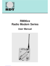
4.1 Dimensions and interfaces
The dimensions of the SATEL-TR49 SnapOn module are 51mm (length) x 30 mm (width) x 4.75
mm (height), weight 12 g. Figure 4.1 shows the dimensions of the module in detail.
Figure 4.1 The module physical dimensions and the holes in millimeters.
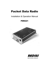
4.2 Dimensions of the Mini PCI Express connector
The Mini PCIe module adopts a standard Mini PCI Express connector that has 52 pins and
complies with the PCI Express Mini Card Electromechanical Specification Revision 1.2.
Figure 4.2 shows a 52-pin Mini PCI Express connector (Molex 67910002 as an example)

SATEL-TR49 SnapOn
Integration Guide, Version 1.7
19
Figure 4.2 Dimensions of the Mini PCI Express connector.
4.3 Installing the Mini PCIe Module on the Host device
To install the SATEL-TR49 SnapOn Mini PCIe module on the host device, do the following.
Step-1: Insert the Mini PCIe module into the Mini PCI Express connector on the host device:
Step-2: Press downwards to fix the Mini PCIe module in the module slot.
Page is loading ...
Page is loading ...
Page is loading ...
Page is loading ...
Page is loading ...
Page is loading ...
Page is loading ...
Page is loading ...
Page is loading ...
Page is loading ...
Page is loading ...
Page is loading ...
Page is loading ...
Page is loading ...
Page is loading ...
Page is loading ...
Page is loading ...
Page is loading ...
Page is loading ...
Page is loading ...
Page is loading ...
Page is loading ...
-
 1
1
-
 2
2
-
 3
3
-
 4
4
-
 5
5
-
 6
6
-
 7
7
-
 8
8
-
 9
9
-
 10
10
-
 11
11
-
 12
12
-
 13
13
-
 14
14
-
 15
15
-
 16
16
-
 17
17
-
 18
18
-
 19
19
-
 20
20
-
 21
21
-
 22
22
-
 23
23
-
 24
24
-
 25
25
-
 26
26
-
 27
27
-
 28
28
-
 29
29
-
 30
30
-
 31
31
-
 32
32
-
 33
33
-
 34
34
-
 35
35
-
 36
36
-
 37
37
-
 38
38
-
 39
39
-
 40
40
-
 41
41
-
 42
42


Ask a question and I''ll find the answer in the document
Finding information in a document is now easier with AI
Related papers
-
Satel SATELLINE-M3-TR3, -TR4, -R4 Integration Guide
-
-
-
-
-
-
-
-
-
Satel EASy+ User manual
Other documents
-
Okayo AB-771T User manual
-
PAC TR-4 User manual
-
FreeWave GX Series User's Reference Manual
-
Magnadyne MV-TX2 Installation guide
-
Korenix JetWave 1402 User manual
-
 RDT RM96xx User manual
-
PAC TR4 Operating instructions
-
-
-
 Radius PDR221 Installation & Operation Manual

