Page is loading ...

Owner’s Manual
AIR COMPRESSOR
3-gallon
1 HP
Oil Lubricated
Model No. 395-226
Your air compressor has been engineered and manufactured to Huskyʼs high standard for
dependability, ease of operation and operator safety. When properly cared for, it will give
you years of rugged, trouble-free performance. Thank you for buying a Husky product.
10/13/2011
Part No. 101-3350
CAUTION:
Before using this product, read this
manual and follow all its Safety
Rules and Operating Instructions.
• Safety Instructions
• Installation & Operation
• Maintenance & Storage
• Troubleshooting Guide
• Parts List
• Español, p. 13

TABLE OF CONTENTS
Page
Safety Instructions . . . . . . . . . . . . . . . . . . . . . . . . . . . . . . . . . . . . . . . . . . . . . . . . . . . . . . . . . . . . . . . . .1
Important Safety Instructions & Guidelines . . . . . . . . . . . . . . . . . . . . . . . . . . . . . . . . . . . . . . . . . . . . . .1
Specifications . . . . . . . . . . . . . . . . . . . . . . . . . . . . . . . . . . . . . . . . . . . . . . . . . . . . . . . . . . . . . . . . . . . .2
Glossary . . . . . . . . . . . . . . . . . . . . . . . . . . . . . . . . . . . . . . . . . . . . . . . . . . . . . . . . . . . . . . . . . . . . . . . .2
Duty Cycle . . . . . . . . . . . . . . . . . . . . . . . . . . . . . . . . . . . . . . . . . . . . . . . . . . . . . . . . . . . . . . . . . . . . . . .2
Parts & Features . . . . . . . . . . . . . . . . . . . . . . . . . . . . . . . . . . . . . . . . . . . . . . . . . . . . . . . . . . . . . . . . .3
Installation & Assembly . . . . . . . . . . . . . . . . . . . . . . . . . . . . . . . . . . . . . . . . . . . . . . . . . . . . . . . . . . . . .4
Operating Procedures . . . . . . . . . . . . . . . . . . . . . . . . . . . . . . . . . . . . . . . . . . . . . . . . . . . . . . . . . . . . .6
Maintenance . . . . . . . . . . . . . . . . . . . . . . . . . . . . . . . . . . . . . . . . . . . . . . . . . . . . . . . . . . . . . . . . . . . . .7
Storage . . . . . . . . . . . . . . . . . . . . . . . . . . . . . . . . . . . . . . . . . . . . . . . . . . . . . . . . . . . . . . . . . . . . . . . . .7
Troubleshooting Guide . . . . . . . . . . . . . . . . . . . . . . . . . . . . . . . . . . . . . . . . . . . . . . . . . . . . . . . . . . . . .8
Exploded View . . . . . . . . . . . . . . . . . . . . . . . . . . . . . . . . . . . . . . . . . . . . . . . . . . . . . . . . . . . . . . . . . . . .9
Parts List . . . . . . . . . . . . . . . . . . . . . . . . . . . . . . . . . . . . . . . . . . . . . . . . . . . . . . . . . . . . . . . . . . . . . . .10
Warranty . . . . . . . . . . . . . . . . . . . . . . . . . . . . . . . . . . . . . . . . . . . . . . . . . . . . . . . . . . . . . . . . . . . . . . .12

1
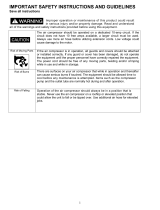
Safety Instructions
The information listed below should be read and
understood by the operator. This information is
given to protect the user while operating and stor-
ing the air compressor. We utilize the symbols
below to allow the reader to recognize important
information about their safety.
Indicates an imminently hazardous situation
which, if not avoided, will result in death or seri-
ous injury.
CAUTION
Indicates a potentially hazardous situation
which, if not avoided, may result in minor or
moderate injury.
WARNING
Indicates a potentially hazardous situation
which, if not avoided, could result in death or
serious injury.
CAUTION
When used without the safety alert symbol indi-
cates a potentially hazardous situation which, if
not avoided, may result in property damage.
Important Safety Instructions and Guidelines
• Save all instructions
WARNING
Improper operation or maintenance of this product could result in serious injury and/or property
damage. Read and understand all of the warnings and safety instructions provided before using this
equipment.
CALIFORNIA PROPOSITION 65 WARNING: This product
contains chemicals known to the State of California to cause
cancer, birth defects and/or reproductive harm.
CAUTION
The air compressor should be operated on a dedicated 15 amp circuit. If
the circuit does not have 15 free amps available, a larger circuit must be
used. Always use more air hose before utilizing extension cords. All exten-
sion cords used must be 12 gauge with a maximum length of 25 ft. The
circuit fuse type must be a time delay. Low voltage could cause damage to
the motor.
Risk of Moving Parts
If the air compressor is in operation, all guards and covers should be
attached or installed correctly. If any guard or cover has been damaged,
do not operate the equipment until the proper personnel has correctly re-
paired the equipment. The power cord should be free of any moving parts,
twisting and/or crimping while in use and while in storage.
Risk of Burns
There are surfaces on your air compressor that while in operation and
thereafter can cause serious burns if touched. The equipment should be
allowed time to cool before any maintenance is attempted. Items such as
the compressor pump and the outlet tube are normally hot during and after
operation.
Risk of Falling
Operation of the air compressor should always be in a position that is
stable. Never use the air compressor on a rooftop or elevated position that
could allow the unit to fall or be tipped over. Use additional air hose for
elevated jobs.
Risk from Flying Objects
Always wear ANSI Z87.1 approved safety glasses with side shields when
the air compressor is in use. Turn off the air compressor and drain the air
tank before performing any type of maintenance or disassembly of the
hoses or fi ttings. Never point any nozzle or sprayer toward any part of the
body or at other people or animals.
DANGER

2
Important Safety Instructions & Guidelines
Risk to Breathing
Avoid using the air compressor in confi ned areas. Always have adequate
space (12 inches) on all sides of the air compressor. Also keep children,
pets, and others out of the area of operation. This air compressor does
not provide breathable air for anyone or any auxiliary breathing device.
Spraying material will always need to be in another area away from the air
compressor to not allow intake air to damage the air compressor fi lter.
Risk of Electrical Shock
Never utilize the air compressor in the rain or wet conditions. Any electrical
issues or repairs should be performed by authorized personnel such as an
electrician and should comply with all national and local electrical codes.
The air compressor should also have the proper three prong grounding
plug, correct voltage, and adequate fuse protection.
Risk of
Explosion or Fire
Never operate the compressor near combustible materials, gasoline or
solvent vapors. If spraying fl ammable materials, locate the air compressor
at least 20 feet away from the spray area. Never operate the air compres-
sor indoors or in a confi ned area.
Risk of Bursting
Always drain the air compressor tank daily or after each use. If the tank
develops a leak, then replace the air compressor. Never use the air com-
pressor after a leak has been found or try to make any modifi cations to the
tank. Never modify the air compressorʼs factory settings which control the
tank pressure or any other function.
Specifications
Pump . . . . . . . . . . . . . . . . . .Oil-lube, direct drive
Motor Induction. . . . . . . . . . . . . . . . . . . . . . .1 HP
Bore . . . . . . . . . . . . . . . . . . . . . . . . . . . . . . .1.65”
Stroke . . . . . . . . . . . . . . . . . . . . . . . . . . . . . .1.26”
Voltage Single Phase . . . . . . . . . . . . . . .120 VAC
Minimum Circuit Requirement . . . . . . . .15 Amps
Air Tank Capacity . . . . . . . . . . . . . . . . . 3 Gallons
Cut-in Pressure . . . . . . . . . . . . . . . . . . . . 95 PSI
Cut-out Pressure . . . . . . . . . . . . . . . . . . 125 PSI
SCFM @ 90 PSI. . . . . . . . . . . . . . . . . . . . . . . 2.4
Glossary
CFM: Cubic feet per minute.
SCFM: Standard cubic feet per minute; a unit of
measure for air delivery.
PSIG: Pounds per square inch gauge; a unit of
measure for pressure.
ASME: American Society of Mechanical Engineers.
California Code: Unit may comply with California
Code 462 (l) (2)/ (M) (2).
Cut-In Pressure: The air compressor will
automatically start to refill the tank when
the pressure drops below the prescribed
minimum.
Cut-Out Pressure: The point at which the motor
stops when the tank has reached maximum
air pressure.
Code Certification: Products that bear one or more
of the following marks: UL, CUL, ETL, CSA,
have been evaluated by OSHA-certified
independent safety laboratories and meet
the applicable Underwriters Laboratories
Standards for Safety.
Duty Cycle
This is a 50% duty cycle air compressor. Do not run the air compressor more than 30 minutes of
one hour. Doing so could damage the air compressor.

3
Pressure
Relief Tube
Outlet Tube
Oil Fill Cap
Oil Sight Gauge
Parts & Features
See figures below for reference
Air Intake Filter
Provides clean air to the pump and must always be kept free of debris. Check on a daily basis or before each use.
Regulator Gauge
Indicates the outgoing air pressure to the tool and is
controlled by the regulator.
Tank Pressure Gauge
Indicates the reserve air pressure in the tank.
Pressure Switch
This controls the power to the motor and
also the cut-in/cut-out pressure settings.
This switch serves as the Auto-On/Off posi-
tions for the unit.
Tank Drain Valve
Used to drain condensation from the air tank. Located at bottom of tank.
Quick Connect
Offers a quick release feature for attaching and
removing the air hose.
Regulator
The air pressure coming from
the air tank is controlled by the
regulator. To increase the pres-
sure, turn the knob clockwise,
and to decrease the pressure,
turn the knob counterclockwise.
Tank Safety Valve
Used to allow excess tank
pressure to escape into the
atmosphere. This valve should
only open when the tank
pressure is above the maximum
rated pressure.
Check Valve
When the pump is not in operation, the valve closes to retain air pressure inside the tank. An internal component.

4
To Install the Air Intake Filter
Remove the plastic plug from
the compressor head. Remove
the air intake fi lter from the poly
bag and thread it onto the head
of the compressor as shown.
CAUTION
Do not attempt to start the air compressor
without fi rst adding oil to the crankcase. Serious
damage can result unless fi lled with oil. The
pump is shipped without oil from the factory.
Only use non-detergent oils since multi-viscos-
ity motor oils leave carbon deposits on pump
components, thus reducing performance and
compressor life.
WARNING
Drain the tank to release all tank
air pressure before removing the
oil fi ll cap. Be sure the air vent in
the oil fi ll cap (see fi gure to the
right) is free from debris. If air vent
is blocked, pressure can build in
crankcase causing damage to the
compressor and possible personal injury.
Lubrication and Oil
Remove the oil fi ll cap by turning
it counter-clockwise by hand. Fill
the compressor pump with an air
compressor oil such as SAE-30
non-detergent (API CG/CD Heavy
Duty) oil at slow intervals until the oil reaches
the center of the red circle in the sight glass
(see fi gure above). Use SAE-10 during extreme
winter conditions.
Location of the Air Compressor
The air compressor should always be located
in a clean, dry, and well ventilated environment.
The unit should have at minimum, 12 inches of
space on each side. The air fi lter intake should
be free of any debris or obstructions. Check the
air fi lter on a daily basis to be sure it is clean and
in working order.
Installation & Assembly
WARNING
The air compressor should be turned off and unplugged from the power source before any mainte-
nance is performed as well as the air bled from the tank and the unit allowed time to cool. Personal
injuries could occur from moving parts, electrical sources, compressed air or hot surfaces. The regu-
lator assembly must be attached before use. Failure to assemble correctly could result in leaks and
possible injury. If unsure of assembly instructions or you experience diffi culty in the assembly please
call your local service department for further instruction.
Grounding Instructions
This product should be grounded. In the event of
an electrical short circuit, grounding reduces the
risk of electric shock by providing an escape wire
for the electric current. This product is equipped
with a cord having a grounding wire with an ap-
propriate grounding plug. (See the fi gure below.)
The plug must be plugged into an outlet that is
properly installed and grounded in accordance
with all local codes and ordinances. Check with
a qualifi ed electrician or service personnel if
these instructions are not completely understood
or if in doubt as to whether the tool is properly
grounded.
Grounded
Outlet
Grounding Pin
Plug

5
WARNING
Improper installation of the grounding plug will result in a risk of electric shock. If repair or replace-
ment of the cord or plug is necessary, do not connect the grounding wire to either fl at blade terminal.
The wire with insulation having an outer surface that is green with or without yellow stripes is the
grounding wire. Check with a qualifi ed electrician or serviceman if the grounding instructions are not
completely understood, or if in doubt as to whether the product is properly grounded. Do not modify
the plug provided; if it will not fi t the outlet, have the proper outlet installed by a qualifi ed electrician.
This product is for use on a circuit having a nominal rating of 120 volts and is factory-equipped with
a specifi c electric cord and plug to permit connection to a proper electric circuit. Make sure that the
product is connected to an outlet having the same confi guration as the plug. No adapter should be
used with this product. If the product must be reconnected for use on a different type of electric circuit,
qualifi ed service personnel should make the reconnection.
Extension Cords
Use only a 3-wire extension cord that has a 3-blade grounding plug, and a 3-slot receptacle that will
accept the plug on the product. Make sure your extension cord is in good condition. When using an
extension cord, be sure to use one heavy enough to carry the current your product will draw. Cords
must not exceed 25 feet and No. 12 AWG size must be used. An undersized cord will cause a drop in
line voltage resulting in loss of power and overheating.
Break In Procedures
No break in procedure is required by the user. This product is factory tested to ensure proper opera-
tion and performance.
Installation & Assembly
NOTES

6
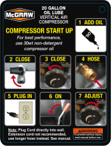
Daily Start-Up Procedures
➀ Set the Auto-On/Off lever to the Off position.
➁ Check the air compressor visually for any
damage or obstruction.
➂ Close the drain valve.
➃ Check the oil level of the pump.
➄ Connect the air hose to the quick connect
socket on the regulator assembly by inserting
the quick connect plug on the air hose into
the quick connect socket. The quick connect
socket collar will snap forward and lock
the plug into place providing an air tight seal
between the socket and plug. To release the
air hose, push the collar back on the quick
connect socket.
➅ Plug the power cord into the proper receptacle.
➆ Turn the Auto-On/Off lever to the On-Auto
Operating Procedures
position, and the compressor will start and
build air pressure in the tank to cut-out
pressure and then shut off automatically.
➇ Adjust the regulator to a PSI setting that is
needed for your application, and be sure it is
within the safety standards required to
perform the task. If using a pneumatic tool,
the manufacturer should have recommendations
in the manual for that particular tool on
operating PSI settings.
Note: The air compressor is now ready for use.
The following infl ation and cleaning accessories
packaged with this unit should only be oper-
ated at maximum pressure of 20-30 PSI: blow
gun, tapered nozzle, infl ation needles, blow gun
adapter.
!
1
4
7
5
6
3
8
Daily Shut-Down Procedures
1. Set the Auto-On/Off lever to the Off position.
2. Unplug the power cord from the receptacle.
3. Set the outlet pressure to zero on the regulator.
4. Remove any air tools or accessories. When
draining the tank, always use ear and eye
protection. Drain the tank in a suitable
location; condensation will be present in most
cases of draining.
5. Open the drain valve allowing air to bleed
from the tank. After all of the air has bled from
the tank, close the drain valve to prevent
debris buildup in the valve.
CAUTION
When draining the tank, always use ear and eye
protection. Drain the tank in a suitable location;
condensation will be present in most cases of
draining.
WARNING
Water that remains in the tank during storage
will corrode and weaken the air tank which could
cause the tank to rupture. To avoid serious injury,
be sure to drain the tank after each use or daily.

7
NOTE: Any service procedure not covered in the maintenance schedule below should be performed
by qualifi ed service personnel.
Maintenance
Items to Check/Change Before each
use or daily
After fi rst 10
hours
Every 100
hours
Check Tank Safety Valve X
Overall Unit Visual Check X
Check Oil Level X
Change Oil X X
Check Air Filter (more frequently in dusty or humid
environments)
X
Drain Tank (after each use or daily) X
CAUTION
To ensure effi cient operation and longer life of
the air compressor unit, a routine maintenance
schedule should be followed. The following
schedule is geared toward a consumer whose
compressor is used in a normal working environ-
ment on a daily basis. If necessary, the schedule
should be modifi ed to suit the conditions under
which your compressor is used. The modifi ca-
tions will depend upon the hours of operation
and the working environment. Air compressors
used in an extremely dirty and/or hostile envi-
ronment will require a greater frequency of all
maintenance checks.
WARNING
The air compressor should be turned off and
unplugged from the power source before any
maintenance is performed as well as the air
bled from the tank and the unit allowed time to
cool. Personal injuries could occur from moving
parts, electrical sources, compressed air or hot
surfaces.
1. Turn the unit off and unplug the power cord
from the receptacle.
2. Allow the compressor time to cool if it has been
in operation.
3.
Open the drain valve to bleed all air from the tank.
4. Close the drain valve.
5. Remove the oil fi ll cap on the pump.
6. Remove the sight glass with a box end wrench
or socket. Drain the oil into a suitable container
and dispose of properly. The compressor may
need to be tipped slightly towards the drain hole
to allow all of the oil to drain.
7. Reattach the sight glass. Note: Torque the sight
glass 10-12 inch lbs. when re-assembling. Be
sure the gasket is between the sight glass and
the pump crankcase.
8. Refi ll the compressor pump with an air
compressor oil such as SAE-30 non-detergent
(API CG/CD Heavy Duty) oil at slow intervals
until the oil reaches the center of the red circle
in the sight glass. Use a SAE-10 during extreme
winter conditions.
Oil Changing
For changing the pump oil, be sure to do the following:
Storage
For storing the air compressor, be sure to do the following:
1. Turn the unit off and unplug the power cord
from the receptacle.
2. Remove all air hoses, accessories, and air tools
from the air compressor.
3. Perform the daily maintenance schedule.
4. Open the drain valve to bleed all air from the tank.
5. Close the drain valve.
6. Store the air compressor in a clean and dry
location.

8
The air compressor should be turned off and unplugged from the power source before any mainte-
nance is performed as well as the air bled from the tank and the unit allowed time to cool. Personal
injuries could occur from moving parts, electrical sources, compressed air, or hot surfaces.
Troubleshooting Guide
PROBLEM POSSIBLE CORRECTION
Air leaks at the check
valve or at the pres-
sure relief valve.
A defective check valve results in a constant air leak at the pressure relief
valve when there is pressure in the tank and the compressor is shut off.
Drain the tank, then remove and clean or replace the check valve.
Air leaks between
head and cylinder.
Be sure of proper torque on head bolts. If leak remains, contact a service
technician.
Air leak from safety
valve.
Operate the safety valve manually by pulling on the ring. If the valve con-
tinues to leak when in the closed position, it should be replaced.
Pressure reading on
the regulated pressure
gauge drops when an
accessory is used.
If there is an excessive amount of pressure drop when the accessory is
used, replace the regulator.
NOTE:
Adjust the regulated pressure under fl ow conditions (while accessory is
being used). It is normal for the gauge to show minimal pressure loss
during initial use of the tool.
Excessive tank pres-
sure.
Move the Auto-On/Off lever to the Off position. If the unit doesnʼt shut off,
unplug it from the power source and contact a service technician.
Motor will not start. Make sure power cord is plugged in and the switch is on. Inspect for the
proper size fuse in your circuit box. If the fuse was tripped, reset it and
restart the unit. If repeated tripping occurs, replace the check valve or
contact a service technician.
Make sure the Thermal Overload Switch has not tripped. The motor has
a built in thermal cut out that trips when necessary to protect the motor
from damage when overheated. To reset the motor overload toggle the
pressure switch Auto/Off lever to the Off position and unplug the unit from
the power outlet. Allow 10 minutes (minimum) for motor overload cut-out
to cool and reset. Unit can then be plugged in and re-started.
Excessive moisture in
the discharge air.
Remove the water in the tank by draining after each use. High humidity
environments will cause excessive condensation. Utilize water fi lters on
your air line.
NOTE:
Water condensation is not caused by compressor malfunction. Be sure
the compressorʼs air output is greater than your toolʼs air consumption
rate.
Air leaks from the tank
body or tank welds.
Never drill into, weld or otherwise modify the air tank or it will weaken.
The tank can rupture or explode. Compressor cannot be repaired. Dis-
continue use of the air compressor.

9
Husky Air Compressor Model 395-226
Exploded View
1
2
3
4
5
6
7
8
9
10
2
11
12
13
14
15
16
17
18
19
20
21
22
23
24
25
26
27
33
36
35
34
37
42
43
44
45
48
47
46
28
40
41
49
50
51
52
53
54
49
40
41
55
56
57
58
59
60
61
62
63
39
40
41
28
38

10
Husky Air Compressor Model 395-226 - Parts List
Ref.
#
Kit
#
Part
Number
Description Qty
13
Screw, M6 X 1.0mm X
30mm
4
2 3 Washer, Lock M6 8
3 3 E100227 Head, Cylinder 1
4 1, 3
Gasket, Head to Valve
Plate
1
5 3 E100228 Plate, Valve 2
6 3 E100229 Valve Reed 2
7 1, 3 Gasket, Valve Plate 1
8 1, 3
Gasket, Cylinder to Valve
Plate
1
9 2, 3 E101113 Cylinder 1
10 3
Screw, SHC M6 x 1.0
x 20MM
4
11 1 & 3 Gasket, Cylinder, Lower 1
12 3 Eccentric for L1 1
13 3 Nut, Hex, M6x1.0 1
14 2, 3
Screw, SHC M6 x 1.0
x 20MM
1
15 2, 3
L1 Piston/ Connecting
Rod Assembly
1
16 1, 3 Baffle for L1 1
17 3 E100087 Cap, Oil Fill w/o-Ring 1
18 3 E101214 Cover, Crankcase for L1 1
19 3 E100078 Plug, oil sight w/seal 1
20 3
Screw, HFH M5 x 0.8 x
15MM (Yellow Zinc Dich
Plate)
4
21 3 Motor/Pump, L1B2 1
22 3 E100860 Fan, Motor F1 125mm 1
23 3 Ring, Snap, Outer, 15mm 1
24 3 E100247 Capacitor, Running 1
25 3 E100248 Capacitor, Starting 1
26 3
Washer, Tooth Lock,
8mm
2
27 3
Nut, M8x1.25, ZDC
6.5MM TALL
10
28 N/A
29 N/A
30 N/A
31 N/A
32 N/A
Ref.
#
Kit
#
Part
Number
Description Qty
33 E105151
Cord, Power 16/3 AWG
Type SJT 6’ Long
1
34 4 Base, Air Filter 1
35 4 E101613 Element, Intake Filter 1
36 4 Cover, Filter (HUSKY) 1
37 3
Assembly, Motor/Pump,
L1B2 w/RH Exhaust
1
38 E100809
Fitting, Elbow, 3/8NPT x
3/8 Compression
1
39
Bolt, SHC M8 x 1.25 x
16MM ( ZDC Plate)
8
40 Washer, Lock, M8 12
41 Washer, Flat, M8 16
42 5 Ferrule, 1/4” 2
43 5 Nut, Comp, 1/4” 2
44 5 Tube, Relief 1/4” Copper 1
45 E101362
Valve, Check, 90 Degree
Left
1
46 6 Nut, Comp, 3/8” 2
47 6 Ferrule, 3/8” 2
48 6
Assy, Outlet tube Finned
3/8” Cu
1
49
Screw, HH M8 x 1.25
x 20MM
8
50 E105137 Foot, Rubber (HUSKY) 4
51 E100098 Valve, Drain Multi-Turn 1
52 Weldment, Tank 3 Gallon 1
53 E105135 Shroud, (HUSKY) 1
54
Screw, HFPH M5 x 0.8 x
10mm ( ZDC Plate)
6
55 E104311 Handle, roll Bar 1
56 E105686 Grip, Handle 1
57 E102822 Quick Connect, Steel 1
58 E100971
Regulator, 3-Port, 1/4
NPT
1
59 E102595 Valve, Safety 1
60 E103339
Gauge, Pressure (38mm
w/125 PSI R/L)
2
61 E100594
Restraint, Power Cord -
16/3 SJT
2
62 E100957
Assy, Switch, Pressure
(125 PSI)
1
63 Nipple, 1/4” mnpt x 35mm 2

11
Husky Air Compressor Model 395-226 - Parts List
Note: Any part/kit number field without a number is not available. Descriptions are provided for reference only. Kit numbers, descrip-
tions, and included components are listed below:
Kit No. Part No. Description Reference No.
1 E100959 Kit, Gasket 4,7,8,11 & 16
2 E100251 Kit, Piston - (Note: Order Gasket Kit #1, as well, when ordering this kit) 9,14,15
3 E105154 Kit, L1B2 Motor/Pump Assy. w/RH Exhaust 1 - 27, 37
4 E105153 Kit, Air Filter 34-36
5 E104308 Kit, 1/4” Copper Pressure Relief Tube 42-44
6 E101334 Kit, Finned Cu 3/8” Outlet Tube 46-48
NOTES

WARRANTY
LIMITED WARRANTY STATEMENT
MAT Holdings, Inc. warrants to the original retail
purchaser that this MAT Holdings, Inc. product
is free from defect in material and workmanship
and agrees to repair or replace, at MAT Holdings,
Inc.ʼs discretion, any defective product free of
charge within these time periods from the date of
purchase.
■ Two year if the product is used for personal,
family or household use;
■ 90 days, if used for any other purpose, such
as commercial or rental.
This warranty extends to the original retail pur-
chaser only and commences on the date of the
original retail purchase.
Any part of the MAT Holdings, Inc. product.manu-
factured or supplied by MAT Holdings, Inc. and
found in the reasonable judgment of MAT Hold-
ings, Inc. to be defective in material or workman-
ship will be repaired or replaced by an authorized
MAT Holdings, Inc. service dealer without charge
for parts and labor.
The product, including any defective part, must
be returned to an authorized service dealer within
the warranty period. The expense of delivering the
MAT Holdings, Inc. product to the dealer for war-
ranty work and the expense of returning it back
to the owner after repair or replacement will be
paid by the owner. MAT Holdings, Inc.ʼs responsi-
bility in respect to claims is limited to making the
required repairs or replacements and no claim of
breach of warranty shall be cause for cancellation
or rescission of the contract of sale of any MAT
Holdings, Inc. product. Proof of purchase will be
required by the dealer to substantiate any warran-
ty claim. All warranty work must be performed by
an authorized MAT Holdings, Inc. service dealer.
This warranty is limited to ninety (90) days from
the date of original retail purchase for any MAT
Holdings, Inc. product that is used for rental or
commercial purposes, or any other income-pro-
ducing purpose.
This warranty does not cover any MAT Hold-
ings, Inc. product that has been subject to mis-
use, neglect, negligence, or accident, or that
has been operated in any way contrary to the
operating instructions as specifi ed in this op-
eratorʼs manual. This warranty does not apply to
any damage to the MAT Holdings, Inc. product
that is the result of improper maintenance or to
any MAT Holdings, Inc. product that has been
altered or modifi ed. The warranty does not ex-
tend to repairs made necessary by normal wear
or by the use of parts or accessories which are
either INCOMPATIBLE WITH THE MAT HOLD-
INGS, INC. product or adversely affect its
operation, performance, or durability.
MAT Holdings, Inc. reserves the right to change
or improve the design of any MAT Holdings, Inc.
product without assuming any obligation to mod-
ify any product previously manufactured.
ALL IMPLIED WARRANTIES ARE LIMITED IN
DURATION
TO THE STATED WARRANTY PE-
RIOD. ACCORDINGLY,
ANY SUCH IMPLIED
WARRANTIES INCLUDING MERCHANTABIL-
ITY, FITNESS FOR A PARTICULAR PURPOSE,
OR OTHERWISE, ARE DISCLAIMED IN THEIR
ENTIRETY AFTER THE EXPIRATION OF THE
APPROPRIATE TWO-YEAR OR NINETY DAY
WARRANTY PERIOD. MAT Holdings, Inc.ʼs
OBLIGATION UNDER THIS WARRANTY IS
STRICTLY AND EXCLUSIVELY LIMITED TO
THE REPAIR OR REPLACEMENT OF DEFEC-
TIVE PARTS AND MAT Holdings, Inc. DOES NOT
ASSUME OR AUTHORIZE ANYONE TO AS-
SUME FOR THEM ANY OTHER OBLIGATION.
SOME STATES DO NOT ALLOW LIMITATIONS
ON HOW LONG AN IMPLIED WARRANTY
LASTS, SO THE ABOVE LIMITATION MAY NOT
APPLY TO YOU. MAT Holdings, Inc. ASSUMES
NO RESPONSIBILITY FOR INCIDENTAL, CON-
SEQUENTIAL, OR OTHER DAMAGES INCLUD-
ING, BUT NOT LIMITED TO, EXPENSE OF RE-
TURNING THE MAT Holdings, Inc. PRODUCT
TO AN AUTHORIZED SERVICE DEALER AND
EXPENSE OF DELIVERING IT BACK TO THE
OWNER, MECHANICʼS TRAVEL TIME, TELE-
PHONE OR TELEGRAM CHARGES, RENTAL
OF A LIKE PRODUCT DURING THE TIME WAR-
RANTY SERVICE IS BEING PERFORMED,
TRAVEL, LOSS OR DAMAGE TO PERSONAL
PROPERTY, LOSS OF REVENUE, LOSS OF
USE OF THE PRODUCT, LOSS OF TIME, OR
INCONVENIENCE. SOME STATES DO NOT AL-
LOW THE EXCLUSION OR LIMITATION OF IN-
CIDENTAL OR CONSEQUENTIAL DAMAGES,
SO THE ABOVE LIMITATION OR EXCLUSION
MAY NOT APPLY TO YOU.
This warranty gives you specifi c legal rights, and
you may also have other rights which vary from
state to state.
This warranty applies to all MAT Holdings, Inc.
products manufactured or supplied by MAT Holdings,
Inc. and sold in the United States and Canada.
To locate your nearest service dealer, dial 1-888-
859-4549.

23
Husky Air Compressor Model 395-226
Parts List
1
2
3
4
5
6
7
8
9
10
2
11
12
13
14
15
16
17
18
19
20
21
22
23
24
25
26
27
33
36
35
34
37
42
43
44
45
48
47
46
28
40
41
49
50
51
52
53
54
49
40
41
55
56
57
58
59
60
61
62
63
39
40
41
28
38

GARANTÍA
DECLARACIÓN DE LA GARANTÍA LIMITADA
MAT Holdings, Inc. garantiza al comprador origi-
nal al menudeo que este producto de MAT Hold-
ings, Inc. carece de defectos en los materiales y
mano de obra y acuerda reparar o reemplazar,
a la sola discreción de MAT Holdings, Inc., cual-
quier producto defectuoso sin cargo alguno den-
tro del plazo establecido después de la fecha de
compra:
J Dos años si el producto se emplea para uso
personal, familiar o doméstico;
J 90 días si el producto se emplea para
cualquier otro propósito, como el uso
comercial o el de alquiler.
Esta garantía únicamente se ofrece al comprador
original al menudeo y comienza en la fecha de la
compra original al menudeo.
Cualquier parte del producto MAT Holdings, Inc.
manufacturado o suministrado por MAT Holdings,
Inc. que, a juicio razonable de MAT Holdings, Inc.
tenga defectos en los materiales o en la mano de
obra, será reparado o remplazado por un esta-
blecimiento de servicio autorizado de productos
MAT Holdings, Inc. , sin cargo alguno al compra-
dor por concepto de piezas y mano de obra.
El producto, incluida toda pieza defectuosa,
debe enviarse a un establecimiento de servicio
autorizado dentro del período de la garantía. El
propietario es responsable de pagar los gastos
de entrega del producto MAT Holdings, Inc. al
establecimiento para cualquier trabajo garan-
tizado y también los gastos de devolución de la
pieza al propietario después de la reparación o
reemplazo. La responsabilidad de MAT Holdings,
Inc.ʼs con respecto a todo reclamo se limita a las
reparaciones o remplazo del producto, y ningún
reclamo de incumplimiento de la garantía será
causante de la cancelación o rescisión del con-
trato de venta de ningún producto de MAT Hold-
ings, Inc. En el establecimiento se requerirá el re-
cibo de compra para respaldar cualquier reclamo
al amparo de la garantía. Todo trabajo cubierto en
la garantía debe ser realizado por un concesion-
ario de servicio autorizado de MAT Holdings, Inc.
Esta garantía se limita a noventa (90) días a
partir de la fecha original de la compra de cual-
quier producto MAT Holdings, Inc. empleado para
propósitos comerciales o de alquiler, o cualquier
otro propósito generador de ingresos.
Esta garantía no cubre ningún producto de MAT
Holdings, Inc. que haya estado sujeto a abuso,
abandono, negligencia o accidente, o que se
haya utilizado en alguna manera de forma con-
traria a las instrucciones de funcionamiento
según se especifi ca en este manual del opera-
dor . Esta garantía no aplica a los daños en el
producto de MAT Holdings, Inc. que resulten de
un mantenimiento indebido ni a producto alguno
de MAT Holdings, Inc. que haya sido alterado o
modifi cado. La garantía no cubre las reparacio-
nes que resulten necesarias por el desgaste nor-
mal o por el uso de piezas o accesorios que sean
incompatibles con el producto de Mat Holdings,
Inc. o que afecten adversamente su funciona-
miento, desempeño o durabilidad.
MAT Holdings, Inc. se reserva el derecho a cam-
biar o mejorar el diseño de cualquier producto de
MAT Holdings, Inc. sin asumir ninguna obligación
de modifi car ningún producto fabricado previa-
mente.
TODAS LAS GARANTÍAS IMPLÍCITAS ESTÁN
LIMITADAS EN DURACIÓN SEGÚN EL PERÍO-
DO DE GARANTÍA DECLARADA. POR CON-
SIGUIENTE, CUALQUIER GARANTÍA IMPLÍCI-
TA, INCLUSO LAS DE COMERCIABILIDAD,
IDONEIDAD PARA UN PROPÓSITO EN PAR-
TICULAR, O DE CUALQUIER TIPO, PIERDEN
TOTALMENTE SU VALIDEZ DESPUÉS DEL
VENCIMIENTO DEL PERÍODO DE GARANTÍA
CORRESPONDIENTE DE DOS AÑOS O NO-
VENTA DÍAS. DE CONFORMIDAD CON ESTA
GARANTÍA, LA OBLIGACIÓN DE MAT Hold-
ings, Inc., SE LIMITA ESTRICTA Y EXCLUSIVA-
MENTE A LA REPARACIÓN O REMPLAZO DE
LAS PIEZAS DEFECTUOSAS, Y MAT Holdings,
Inc., NO ASUME NINGUNA OTRA OBLIGACIÓN,
NI AUTORIZA A NADIE ASUMIRLA A NOMBRE
DE DICHA COMPAÑÍA. ALGUNOS ESTADOS
NO PERMITEN LIMITACIONES EN CUANTO A
LA DURACIÓN DE UNA GARANTÍA IMPLÍCITA,
POR LO CUAL ES POSIBLE QUE LA LIMITACIÓN
ANTERIOR NO SE APLIQUE EN EL CASO DE
USTED. MAT Holdings, Inc. NO ASUME NINGU-
NA RESPONSABILIDAD POR DAÑOS DIREC-
TOS, INDIRECTOS O DE NINGÚN OTRO TIPO,
COMO EL GASTO DE ENVIAR EL PRODUCTO
DE MAT Holdings, Inc. A UN ESTABLECIMIEN-
TO DE SERVICIO AUTORIZADO Y EL GASTO
DE ENVIARLO DE ALLÍ AL PROPIETARIO, EL
TIEMPO DE VIAJE DEL MECÁNICO, CARGOS
TELEFÓNICOS O TELEGRÁFICOS, ALQUILER
DE UN PRODUCTO SUSTITUTO DURANTE EL
TIEMPO DE REALIZACIÓN DEL SERVICIO DE
LA GARANTÍA, VIAJES, PÉRDIDA O DAÑOS A
OBJETOS DE PROPIEDAD PERSONAL, PÉR-
DIDA DE INGRESOS, PÉRDIDA DEL USO DEL
26
/