Page is loading ...

BT7323
CABLE MANAGER BASE
ASSEMBLY AND INSTALLATION
©Copyright 2009.
www.btechavmounts.com
v.0109 OR1BX
Asia Pacific
B-Tech International (Hong Kong) Ltd.
23rd Floor, Manulife Tower, North Point, HK
Tel: (+852) 2556 7337 Fax: (+852) 2556 7321
Email: [email protected]
Europe
B-Tech PRO-AV bvba
Brixtonlaan 32, Zaventem 1930,Brussels, Belgium
Tel: +32 (0)2 720 92 71 Fax: +32 (0)2 725 42 15
Email: [email protected]
North America
B-Tech Audio Video Mounts.
10 Greg Street, #108, Sparks, NV 89431, USA
Tel: (1)800 975 5812 Fax: (1)800 592 2876
Email: [email protected]
Head Office
B-Tech International Ltd.
Bennett House, Long March, Daventry, Northants NN11 4NR, UK
Tel: +44 (0)1327 300 787 Fax: +44 (0)1327 706 562
Email: [email protected]
PAGE 1 / 2
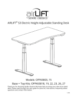
This pack contains:
1 cable manager base
Caution: Do not exceed the maximum weight limit indicated for this product.
Failure to comply may cause instability and possible serious injury.
• Designed to bolt B-Tech 50mm (2”) poles (BT7325 and BT7326) to
desks using a standard cable management hole or a drilled hole
• Integrates with desk cable management holes up to Ø80mm (3.1”)
• Fits desks up to 40mm (1.5”) thick
• Cable management allows the cables to pass through the desk for a
tidy installation
• Maximum load: 90Kg (198lbs)
• Base dimensions: Ø120 (4.7”)
• All fixings included
66
mm (2.6")
36
mm (1.4")
This base is intended for use only with the maximum
weights indicated. Use with heavier than the maximum
indicated may result in instability causing possible injury.
O 120 mm
(4.7")
40
mm (1.5")
MAX
DESK
Made in China
Important Safety Instructions.
Read first
Do not attempt to install this product until all instructions and warnings have been read and
properly understood. Please keep these instructions for future reference.
B-Tech International Limited, its distributors and dealers are not liable or responsible for
damage or injury caused by improper installation, improper use or failure to observe these
safety instructions. In such cases, all guarantees will expire.
General
B-Tech International Ltd recommends that a professional AV installer or other suitably qualified
person install this product. Great care must always be taken during installation as most AV
equipment is of a fragile nature, possibly heavy and easily damaged if dropped.
If you do not fully understand the instructions or are not sure how to install this product safely,
then please consult a professional for advice and/or to install this product for you. Failure to
mount this product correctly may cause serious injury or death both during installation and at
any time thereafter.
Do not mount any AV equipment that exceeds the specific weight limit of the product you are
installing. This weight limit will be clearly stated on each product and its packaging and will
vary from product to product.
Product location
Please pay careful attention to where this product is located.
Fixing hardware
It is highly recommended that all fixing screws be used where supplied and that the purpose of
all other fixing hardware is fully understood. In some cases more AV equipment fixing
hardware will be supplied to accommodate different models of equipment and set up
configurations.
The installer must be satisfied that any supplied fixing hardware is suitable for each specific
installation. If any fixing screws or included hardware are deemed not sufficient for a safe
installation then please consult a professional or your local hardware store.
Hazard limitation
When routing cables take advantage of any built in cable management features that the
product might provide and ensure that all cables are tidy and secure. Check to see that any
moving aspect of the product can do so unhindered by any cabling.
Some products have moving parts and the potential to cause injury through the crushing or
trapping of fingers or other body parts.
Particular attention to the nature of moving parts is required especially when assembling
installing and adjusting during set up.
Immediately after installations double-check that the work done is safe and secure. Double-
check all necessary fixings are present and are of ample tightness.
It is recommended that periodic inspections of the product and its fixing points are made as
frequently as possible to ensure that safety is maintained. If in doubt consult a professional AV
installer or other suitably qualified person.

PAGE 2 / 2
BT7323
PARTS LIST & INSTALLATION INSTRUCTIONS
v.0109 OR1BX
B. Used with desk cable management
hole
Drill a 12mm hole in the
desk at the desired
locaction. Use the M10
X 76 Allen screw
(part
3)
to attach the pole
(sold separately) to the
desk. Tighten screw
from the underside of
desk using the 6mm
Allen key
(part 4).
1
2
1
3
C. Used with drilled hole in desk
Cable managment hole
with insert in desk
3
1
1
Desk with 12mm
drilled hole
Use the M10 Allen screw
(part 3) to attach the
pole (sold separately) to
the desk through the
existing cable
managment hole.
Tighten screw from the
underside of the desk
using the 6mm Allen key
(part 4).
No holes need to be
drilled by the installer for
this configuration.
1
1
3
A. Used with desk cable management hole with
insert
Cable managment
hole
PARTS LIST
1
2
3
4
No PART NAME QTY
1 CABLE MANAGER BASE 2
2 SPACER RING 1
3 M10 X 76 ALLEN SCREW 1
4 6MM ALLEN KEY (FOR PART 3) 1
1
PLEASE KEEP THIS PARTS LIST FOR
FUTURE REFERENCE
BT7325 or
BT7326
Pole (sold
separately)
DESK
DESK
DESK
- Select configuration A,
B or C to suit the
requirements of the
installation.
- For configurations A &
B, the load must be on
the opposite side to the
cable management hole
as shown in FIG 1.
- For a tidy installation,
cables can be passed
down through the pole,
through the cable
manager base and desk
cable management hole.
Fit the rubber spacer over the cable
management hole with insert. Ensure the
sticky side faces upwards. Stick the cable
manager base
(part 1) on top of the spacer.
Use the M10 Allen screw
(part 3) to attach
the pole (sold separately) to the desk through
the existing cable managment hole. Tighten
screw from the underside of the desk using
the 6mm Allen key
(part 4).
No holes need to be drilled by the installer for
this configuration.
FIG 1.
Example
installation
READ FIRST
CABLE MANAGEMENT
HOLE
LOAD THIS SIDE
BT7325 or
BT7326
Pole (sold
separately)
BT7325 or
BT7326
Pole (sold
separately)
/