Page is loading ...

Version: 1.0
QuantaGrid Series
Q71L-4U
Powerful enterprise grade 4U 4-socket server
with unprecedented RAS and scalability
6TFShT Guide

R
EVISION HISTORY REGULATORY AND COMPLIANCE INFORMATION
Revision History
Refer to the table below for the updates made to this technical guide.
Copyright
Copyright © 2014 Quanta Computer Inc. This publication, including all photographs, illus-
trations and software, is protected under international copyright laws, with all rights
reserved. Neither this technical guide, nor any of the material contained herein, may be
reproduced without the express written consent of the manufacturer. All trademarks and
logos are copyrights of their respective owners.
Version 1.0.3 / September 9, 2014
Disclaimer
The information in this document is subject to change without notice. The manufacturer
makes no representations or warranties with respect to the contents hereof and specifi-
cally disclaims any implied warranties of merchantability or fitness for any particular pur-
pose. Furthermore, the manufacturer reserves the right to revise this publication and to
make changes from time to time in the content hereof without obligation of the manufac-
turer to notify any person of such revision or changes.
For the latest information and updates please see www.QuantaQCT.com
All the illustrations in this technical guide are for reference only and are subject to change
without prior notice.
DATE CHAPTER UPDATES

CONVENTIONS
Conventions
Several different typographic conventions are used throughout this manual. Refer to the
following examples for common usage.
Bold type face denotes menu items, buttons and application names.
Italic type face denotes references to other sections, and the names of the folders, menus,
programs, and files.
<Enter> type face denotes keyboard keys.
WARNING!
Warning information appears before the text it references and should not be ignored as
the content may prevent damage to the device.
CAUTION!
CAUTIONS APPEAR BEFORE THE TEXT IT REFERENCES, SIMILAR TO NOTES AND WARNINGS.
CAUTIONS, HOWEVER, APPEAR IN CAPITAL LETTERS AND CONTAIN VITAL HEALTH AND SAFETY
INFORMATION.
Note:
Highlights general or useful information and tips.
!
!

About the System
Chapter 1
This section introduces the system, its different configuration(s) and the main features.

INTRODUCTION ABOUT YOUR SYSTEM
1-1
1.1 Introduction
The QuantaGrid Q71L-4U is a 4-socket 4U server powered by the Intel® Xeon® processor
E7-4800 v2 family. It features significant performance with up to 15 cores per processor, 96
RDIMM memory slots, twelve 2.5" hot-plug disk drives, ten PCIe expansion slots, and GbE/
10GbE/infiniband networking options. These rich features make the QuantaGrid Q71L-4U
system a perfect hardware solution for fast growing businesses that demand higher com-
puting power and memory to run mission-critical applications or better handle large
workloads. When considering extending the value into 4-socket servers, QuantaGrid
Q71L-4U provides higher reliability and flexibility for today’s needs with plenty of flexibil-
ity for tomorrow’s growth.
Specifications
Table 1.1: System Specifications
SPECIFICATIONS DESCRIPTION
Form factor 4U rack mount
Dimensions (W x H x D)
16.69 x 6.8 x 27.71 inches
424 x 174 x 704 mm
Processor
Processor type:
Intel® Xeon® processor E7-4800 v2 product family
Max. TDP support: 155W
Number of processors: 4
Internal Interconnect: 6.4 / 7.2 / 8.0 GT/s
L3 cache: Up to 37.5 MB
Chipset
Intel® C602J
Memory
Total slots: 96
Capacity: up to 3072 GB RDIMM
Memory type: 1600/1333 MHz DDR3 RDIMM
Memory size: 32 GB, 16 GB, 8 GB RDIMM
Storage controller
Onboard (Intel® C602J):
2x SATA 3Gb/s ports
2x SATA 6Gb/s ports
SATA RAID 0, 1, 5, 10
Optional controller:
Quanta LSI® 2008 6Gb/s SAS mezzanine, RAID 0, 1, 10
Quanta LSI® 2308 6Gb/s SAS mezzanine, RAID 0, 1, 10
Quanta LSI® 2108 6Gb/s RAID mezzanine, RAID 0, 1, 5, 10, RAID 6 with
additional RAID key
Quanta LSI® 2208 6Gb/s RAID mezzanine, RAID 0, 1, 5, 10, RAID 6 with
additional RAID key

ABOUT YOUR SYSTEM INTRODUCTION
1-2
Networking
LOM:
Dedicated 10/100 GbE management port
Optional NIC:
Intel® i350 dual-port 1 GbE or Intel® X540 dual-port 10 GbE BASE-T
Quanta Intel® 82599ES dual-port 10G SFP+ mezzanine
Quanta Mellanox® ConnectX-3 QDR dual-port mezzanine
Quanta Mellanox® ConnectX-3 FDR dual-port mezzanine
Expansion slots
The system has a total of thirteen PCIe slots.
(10) Standard PCIe slots:
Two x16 PCIe 3.0, HH 3/4L
Eight x8 PCIe 3.0, HHHL
Slot 2-3 & 6-7: hot-plug
Slot 1,4-5 & 8-10: not hot-plug
Slot 1- 3, 5-6 & 8-10: PCIe Gen 3 x8 lanes, x8 connector, half length
Slot 4 & 7: PCIe Gen 3 x16 lanes, x16 connector, 3/4 length
SAS Riser Slot: PCIe Gen 3 x8 lanes, x8 connector, non hot-plug,
half length
(3) Quanta Dedicated Support:
(2) PCIe slots dedicated for Quanta I/O module support Quanta mez-
zanine and Quanta LAN add-on card (Intel i350 or Intel X540)
(1) PCIe slot dedicated for Quanta SAS Riser card support Quanta
SAS board
Drive bays options Front accessible: 12 x 2.5” hot-plug (4x non hot-plug PCIe SSD support)
Onboard storage 2x USB flash drives
Video Integrated AST2300 with 8MB DDR3 video memory (optional)
Front I/O
3x USB 2.0 ports
1x VGA port
Rear I/O
2x USB 2.0 ports
1x VGA port
1x RS232 serial port
2x 1 GbE or 10G BASE-T RJ45 port
1x GbE RJ45 management port
Optical drive SATA DVD-ROM
TPM Yes
Power supply
2+2 high efficiency redundant 1600W PSU, 80 Plus platinum
3+1 high efficiency redundant 1200W PSU, 80 Plus platinum
Fan 8x hot-plug systems fans
System management IPMI v2.0 compliant, on-board KVM over IP support
Weight (Max. configuration) 42 kg (92.5 lb)
Table 1.1: System Specifications (Continued)
SPECIFICATIONS DESCRIPTION

INTRODUCTION ABOUT YOUR SYSTEM
1-3
Operating environment
Operating temperature: 5°C to 35°C (41°F to 95°F)
Non-operating temperature: -40°C to 65°C (-40°F to 149°F)
Operating relative humidity: 20% to 85%RH
Non-operating relative humidity: 10% to 90%RH
Table 1.1: System Specifications (Continued)
SPECIFICATIONS DESCRIPTION

ABOUT YOUR SYSTEM PACKAGE CONTENTS
1-4
1.2 Package Contents
(1) Q71L-4U system
(4) processor heat sinks
(4) power supply units
(4) power cord (optional)
(1) utility CD (User's Guide included)
(1) rail kit
Note:
Note: For exact shipping contents, contact your Quanta sales representative.

A TOUR OF THE SYSTEM ABOUT THE SYSTEM
1-5
1.3 A Tour of the System
System Overview
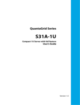
Figure 1-1. System Component Overview
Table 1.2: Component Overview
NO.ITEM DESCRIPTION
1 PCIe slots x10 PCIe slots, including four hot-plug PCIe slots
2 I/O riser LAN riser with Twinville 10G LAN chip on-board.
3 Mid-brace Single mid-brace supporting memory riser installation.
4 Memory riser x8 memory risers supporting up to 12 DIMMs / riser.
5 Chassis 4U height chassis.
6 Hard disk drive bay 2.5” hot-plug hard drive bay (max. x12 HDDs).
7 Operator Panel
Operator Panel includes the following:
Reset button
Power button
Power LED
ID button
ID LED
Fault LED
HDD LED
8 Slimline optical drive System accommodates one optical disk drive (non hot-plug).
9 System fans x8 hot-plug system fans.
10 Processor heat sinks x4 system heat sinks.
1
2
3
4
5
6
7
8
9
10

ABOUT THE SYSTEM SYSTEM OVERVIEW
1-6
System Front View
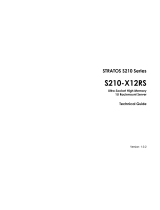
Figure 1-2. System Front View
Table 1.3: Front Panel View
NO.NAME DESCRIPTION
1 Chassis handle Hold to remove chassis from the rack
2 Thumb screw x2 thumb screws to secure chassis to rack
3 Rear LAN LEDs
Indicates LAN activity:
LAN1: bottom LAN port on rear panel.
LAN2: upper LAN port on rear panel.
4 Operator panel
Operator Panel includes the following:
Reset button
Power button
Power LED
ID button
ID LED
Fault LED
HDD LED
5 Video connector Supports connection to external display.
6 USB 2.0 x3 USB (2.0) connectors.
7 Hard disk drive bay 2.5” hot-plug hard drive bay (max. x12 HDDs).
8 Optical disk drive DVD-RW player and writer.
9 Asset tag Used to record system information, such as: MAC and IP addresses.
134561
789
2 2

SYSTEM OVERVIEW ABOUT THE SYSTEM
1-7
System Rear View
Figure 1-3. System Rear View
Table 1.4: Rear Panel View
NO.NAME DESCRIPTION
A SAS riser slot PCIe Gen-3x8, half length
B1
Video port - standard VGA compatible, 15-pin connector supporting up to 1920 x 1200
32bpp@60Hz resolution.
B2 Serial port
B3
I/O riser management Ethernet port (Aspeed AST2300)
Managment port LED
Status LED (bottom) -
Green
On - Link
Blinking - Ethernet link is active
Off - No Ethernet connection
Speed LED (upper)
Green / Amber
Green On - 10 Mbps
Amber On - 100 Mbps
C
I/O riser dual gigabit Ethernet ports:
Two LAN ports, RJ45 connector; bottom: LAN1, upper: LAN2
LAN port LED
Status LED (bottom) -
Green
On - Ethernet link is detected
Blinking - Ethernet link is active
Off - No Ethernet connection
Speed LED (upper) -
Amber/Blue (X540)
Yellow/Green (i350)
X540 Installed i350 Installed
Off - 10 / 100 Mbps Off - 10 Mbps
Amber On - 1 Gbps Yellow On - 100 Mbps
Blue On - 10 Gbps Green On - 1 Gbps
D Dual 10 gigabit Ethernet ports (optional, mezzanine installed to I/O riser module)
CE
①②③④⑤⑥⑦⑧⑨⑩
F
A B1 B2 D
B3G
HJ
C
K

ABOUT THE SYSTEM SYSTEM OVERVIEW
1-8
PSU View
Figure 1-4. PSU Rear Panel View
E
F Power supply unit, see PSU View on page 1-8.
G System ID button
H System ID LED: Blue ID identifies the system locally or through server management
J System status/fault LED
K USB ports (2.0) x2
Table 1.5: Rear Panel View
NO.NAME DESCRIPTION
1 Handle Hold to remove the PSU from the chassis bay.
2 Power supply fan Do not cover to avoid system overheating.
3 PSU status LED See Power Supply LED Definition on page 1-10.
4
AC input power
connector
Connect power plug.
5 Release latch Press and hold to unlock PSU from chassis bay.
Table 1.4: Rear Panel View (Continued)
NO.NAME DESCRIPTION
Slot1: PCIe Gen-3x8 Slot6 PCIe Gen-3x8, hot-plug
Slot2: PCIe Gen-3x8, hot-plug Slot7 PCIe Gen-3x16, hot-plug
Slot3: PCIe Gen-3x8, hot-plug Slot8: PCIe Gen-3x8
Slot4: PCIe Gen-3x16 Slot9: PCIe Gen-3x8
Slot5: PCIe Gen-3x8 Slot10: PCIe Gen-3x8
1 23 45

LED DEFINITIONS ABOUT THE SYSTEM
1-9
LED Definitions
Operator Panel LED Definition
Figure 1-5. Operator Panel View
The following table describes the listed LED functions found in the Operator Panel:
HDD LED (1)
Status LED (2)
ID LED (3), ID Button (*)
Power LED (4)
Table 1.6: Operator Panel LED Definition
NO. NAME STATE DESCRIPTION
1 HDD LED
Solid Blue HDD is active and data transfer is in progress.
Off HDD is in idle state.
2 Status LED
Blinking Amber IRMC condition indicating an error.
Off Non-critical alarm.
3 ID LED
Blinking Blue Identification activity detected.
Off No Identification activity initiated.
4 Power LED
Solid Blue System is powered on.
Off System is in powered off state.
1 23 4*

ABOUT THE SYSTEM LED DEFINITIONS
1-10
Power Supply LED Definition
The following information describes the single bi-colored LED configuration for the power
system.
AC_OK: Solid green (Bi-colored LED)
Fault (Fault of any kind): Amber (Bi-colored LED)
PSOK# (Power no-fault): Solid green (Bi-colored LED)
LED Indicator States
Redundant Mode States (only for RPSU SKU)
Table 1.7: LED Indicator States
POWER SUPPLY CONDITION LED STATE
+12V output and PSOK Green
Standby mode Blinking Green
OCP, OVP, UVP, OTP, and Fan fail Amber
Table 1.8: Redundant Mode LED States
MODE LED
PSU1 Standby mode Green: Blinking
PSU2 12V power on Green: Solid
PSU1 12V power on Green: Solid
PSU2 12V power on Green: Solid
PSU1 AC off Off
PSU2 Standby mode Green: Blinking
PSU1 AC off Off
PSU2 12V power on Green: Solid

Regulatory and Compliance
Information
Chapter 2
This section provides regulatory and compliance information applicable to this system.


/