
Opus 910
WIRELESS MICROPHONE SYSTEM
Operating Instructions


3
CONTENTS
OPERATING INSTRUCTIONS Opus 910
Important Safety Information . . . . . . . . . . . . . . . . . . . Page 4
NE 911 / 912 / 914 Diversity Receiver . . . . . . . . . . . . . Page 8
ZAS 900 Antenna Splitter . . . . . . . . . . . . . . . . . . . . . . Page 16
Connection to a PC . . . . . . . . . . . . . . . . . . . . . . . . . . Page 18
S 910 C / S 910 M Handheld Transmitters . . . . . . . . . Page 19
TS 910 Beltpack Transmitter . . . . . . . . . . . . . . . . . . . . Page 26
General Instructions for all Transmitters . . . . . . . . . . . Page 32
Trouble Shooting. . . . . . . . . . . . . . . . . . . . . . . . . . . . . Page 33
Maintenance. . . . . . . . . . . . . . . . . . . . . . . . . . . . . . . . Page 34
Licensing. . . . . . . . . . . . . . . . . . . . . . . . . . . . . . . . . . . Page 34
Components. . . . . . . . . . . . . . . . . . . . . . . . . . . . . . . . Page 34
Optional Accessories . . . . . . . . . . . . . . . . . . . . . . . . . . Page 35
Technical Specifications . . . . . . . . . . . . . . . . . . . . . . . . Page 36

4
OPERATING INSTRUCTIONS OPUS 910
Thank you for selecting the Opus 910 wireless system. Please take some time to read carefully
through this manual before setting up the equipment.
Important:
• When you unpack the product, inspect it for transport damage. If you do find transport damage,
notify the transportation company without delay. Delay in reporting transport damage could result
in the loss of your rights to compensation.
Receiver
• READ these instructions.
• KEEP these instructions.
• HEED all warnings.
• Follow all instructions.
• Do not use this apparatus near water.
• Clean only with a dry cloth.
• Do not block any ventilation openings. Install in accordance with the manufacturer’s instructions.
• Do not install near any heat sources such as radiators, heat registers, stoves or other apparatus
(including amplifiers) that produce heat.
• Do not defeat the safety purpose of the polarised or grounding-type plug. A polarised plug has
two blades with one wider than the other. A grounding type plug has two blades and a third
grounding prong. The wide blade or the third prong are provided for your safety. If the provided
plug does not fit into your outlet, consult an electrician for replacement of the obsolete outlet.
• Protect the power cord from being walked on or pinched particularly at plugs, convenience
receptacles, and the point where they exit from the apparatus.
• Only use attachements/accessories specified by the manufacturer.
• Use only with the cart, stand, tripod, bracket or table specified by the manufacturer or sold with
the apparatus. When a cart is used, use caution when moving the cart/apparatus combination to
avoid injury from tip-over.
• Unplug this apparatus during lightning storms or when unused for long periods of time.
• Refer all servicing to qualified service personnel. Servicing is required when the apparatus has been
damaged in any way, such as power-supply cord or plug is damaged, liquid has been spilled or
objects have fallen into the apparatus, the apparatus has been exposed to rain or moisture, does
not operate normally, or has been dropped.
• The equipment must be set up so that the mains switch, mains plug and all connection on the rear
of the device are easily accessible.
• The equipment must be connected to a mains socket that has an earth contact.
• Never expose the equipment to rain or a high level of humidity. For this reason do not install it in
the immediate vicinity of swimming pools, showers, damp basement rooms or other areas with
unusually high atmospheric humidity.
• Do not use the device/s outside. WARNING: To reduce the risk of fire or electric shock, do not
expose this/these device/s to rain or moisture.
• Never place objects containing liquid (e.g. vases or drinking glasses) on the equipment. Liquids in
the equipment could cause a short circuit.
• Lay all connection cables so that they do not present a trip hazard.
• Check whether the connection figures comply with the existing mains supply. Serious damage
could occur due to connecting the system to the wrong power supply. An incorrect mains voltage
could damage the equipment or cause an electric shock.
Important Safety Instructions

5
Transmitter
• Protect the transmitter from moisture and sudden impacts. You could either injure yourself or others
or damage the transmitter.
• Do not blow into the microphone. In a condenser microphone this could damage the transformer.
It is preferable to carry out a speech trial.
• Clip-on microphones are often very compact. If they are accidentally swallowed there is a risk of
choking. Always keep this type of microphone away from small children.
• Always switch off the transmitter before charging or changing the battery.
• If the transmitter is fitted with a normal battery, never charge it in the charging unit. The transmitter
or the batteries could be destroyed. There is a risk of explosion.
• The normal commercial 9 V alkaline batteries can have a length tolerance of 2 - 3 mm. When
changing the battery always ensure good contact.
• From time to time the battery contacts should be cleaned with a soft cloth moistened with spirits
or alcohol.
• If the transmitter is not being used for weeks or months, please remove the batteries. Batteries can
leak when not being used for a long time and corrode the conductor strips and components.
Repair is not then possible. In this case all warranty claims are null and void. The description “leak
proof” on batteries is no guarantee that they will not run out.
• Never take batteries apart yourself. The battery acid contained will damage skin and clothing.
• Do not throw used batteries into the domestic rubbish, but hand them in to local collection points.
• This equipment needs adequate ventilation. Do not cover ventilation grilles. If the heat it generates
cannot be dissipated, the equipment could be damaged or flammable materials in its immediate
vicinity could be ignited. Take care to ensure that the air can circulate freely through the ventilation
grilles and keep flammable materials away.
• Never place naked flames near the equipment.
• If the equipment causes a blown fuse or a short circuit, disconnect it from the mains and have it
checked and repaired.
• Do not open the equipment without authorisation. You could receive an electric shock. Leave all
service work to authorised expert personnel.
• Do not hold the mains cable with wet hands. There must be no water or dust on the contact pins.
In both cases you could receive an electric shock.
• The mains cable must be firmly connected. If it is loose there is a fire hazard.
• Always pull out the mains cable from the mains and/or from the equipment by the plug - never by
the cable. The cable could be damaged and cause an electric shock or fire.
• If the power cable is connected, avoid contact of the unit with other metallic objects.
• Do not insert objects into the ventilation grilles or other openings. You could damage the
equipment and/or injure yourself.
• Do not use the equipment if the mains plug is damaged.
• When installing the device into a 19" rack, make sure that the mains switch, mains plug and all
connection on the rear of the device are easily accessible.
• When connecting a headphone, please make sure that the volume is turned down to minimum.
Adjust the volume after putting on the headphone. Do not set the volume too high, as you could
permanently damage your hearing.

6
FCC Regulation
FCC ID: OSDTS910 for TS 910 M, TS 910 C
OSDS910M for S 910 M
OSDS910C for S 910 C
Canada IC: 3628A-S910M for S 910 M
3628A-S910C for S 910 C
3628A-TS910 for TS 910 M, TS 910 C
3628A-NE91X for NE 911
3628A-NE91X for NE 912
3628A-NE91X for NE 914
NOTE: This equipment has been tested and found to comply with the limits for a Class B digital
device, pursuant to Part 15 of the FCC Rules. These limits are designed to provide reasonable
protection against harmful interference in a residential installation. This equipment generates, uses
and can radiate radio frequency energy and, if not installed and used in accordance with the
instructions, may cause harmful interference to radio communications. However, there is no
guarantee that interference will not occur in a particular installation. If this equipment does cause
harmful interference to radio or television reception, which can be determined by turning the
equipment off and on, the user is encouraged to try to correct the interference by one or more of
the following measures:
• Reorient or relocate the receiving antenna.
• Increase the separation between the equipment and receiver.
• Connect the equipment into an outlet on a circuit different from that to which the receiver is
connected.
• Consult the dealer or an experienced radio/TV technician for help.
NOTICE:
Changes or modifications made to this equipment not expressly approved by
beyerdynamic GmbH & Co. KG may void the FCC authorization to operate this equipment.
NOTICE:
This device complies with Part 15 of the FCC Rules and with RSS-210 of Industry Canada.
Operation is subject to the following two conditions:
(1) this device may not cause harmful interference, and
(2) this device must accept any interference received, including interference that may cause
undesired operation.
NOTICE:
This Class B digital apparatus complies with Canadian ICES-003.
Cet appareil numérique de la classe B est conforme à la norme NMB-003 du Canada.
For USA:
OPERATION OF WIRELESS MICROPHONES IN THE 700 MHZ BAND IS PROHIBITED AFTER
JUNE 12, 2010.

7
CONSUMER ALERT
Most users do not need a license to operate this wireless microphone system. Nevertheless, operating
this microphone system without a license is subject to certain restrictions: the system may not cause
harmful interference; it must operate at a low power level (not in excess of 50 milliwatts); and it has
no protection from interference received from any other device.
Purchasers should also be aware that FCC is currently evaluating use of wireless microphone systems,
and these rules are subject to change.
For more information, call the FCC at 1-888-CALL-FCC (TTY: 1-888-TELL-FCC) or visit the FCC´s wire-
less microphone website at www.fcc.gov/cgb/wirelessmicrophones.

8
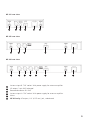
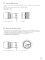
1. NE 911 / 912 / 914 Diversity Receiver
1.1 Controls and Indicators
NE 911 front view
Power switch with LED indicator
Headphone input
Volume control for headphone input to listen to individual receiving channels
NE 912 / 914: Press the volume control to select the receiving channel
Display
ACT button
Scan button
Menu control (for selecting different settings)
ESC button
Antenna connection when connecting the antennae on the front
1
2
3
4
5
6
7
8
9
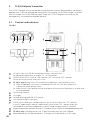
NE 912 front view
NE 914 front view
1 2 5 4 6 7 8
3
3
3
1 2 5 4 6 7 8 99
1 2 5 4 6 7
8 9
9

9
Antenna input B. TNC socket. With power supply for antenna amplifier.
AF output, 3-pin XLR, balanced
Remote connection IN / OUT
Antenna input A. TNC socket. With power supply for antenna amplifier.
Mains
NE 911 only: AF output, 1/4" (6.35 mm) jack, unbalanced
NE 912 rear view
NE 911 rear view
NE 914 rear view
11
12
13
14
15
10
10 11 15 12 14 13
10 11 11 12 1413
10 11 11 11 11 12 1413

10
1.2 How to connect the Antennae
Connect the antennae to the TNC sockets and ( . Set them at an angle (60°).
Please note that for diversity operation both antennae have to be connected. A weighting circuit
silently switches the signal with the better S/N ratio to the output.
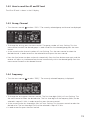
1.4 LC-Display and Menu Settings
On the LC-Display all operating parameters such as RF and AF level will be shown. Using the “Menu“
control you can select from 6 options. The selected function is surrounded by a square frame and
shown at the bottom of the LC-Display.
By selecting the ESC button you can cancel the current entry into the menu to display the
previous setting.
To select the individual receiving channels of the NE 912 / 914 for entering the menu settings, press
the menu control until the green LED between the ACT and the SCAN button is flashing. Turn the
menu control to select the receiving channel. The green LED of the selected receiving channel will
flash. Press the menu control to confirm. The green LED will illuminate permanently.
The functions and operation are described in the following.
1.3 Setting up
1. Place the diversity receiver in the same room or area as the transmitters. Make sure the diversity
receiver is placed as close as possible to the transmitter.
2. Do not place the diversity receiver near digitally controlled equipment.
3. Connect the AF-output to the corresponding input of the mixing console or amplifier.
4. Connect the receiver to AC power.
5. Switch on the receiver . The red LED will illuminate.
6. If you use the receiver on a tabletop, please stick the supplied rubber pads to the bottom of the
receiver to ensure a sufficient ventilation.
1310
1
1.4.1 Diversity indication of the Receiving Channel
Each receiving module has two separate receiving circuits, one for each antenna. The signal with the
better S/N ratio is switched to the output. The received diversity channel is shown in the LC-display.
7
7
8

11
1.4.2 How to read the AF and RF level
The AF or RF level is shown in the LC-display.
1.4.3 Group, Channel
• Turn the menu control to select “G/CH”. The currently selected group and channel are displayed.
• To change the setting, press the menu control. The group number will start flashing. Turn the
menu control to select the desired group. In order to confirm the selected group press the menu
control.
• At the same time the channel number will start flashing. Turn the menu control to select the
desired channel. In order to confirm the selected channel press the menu control.
• Press the Scan button to select a channel automatically. Press the Scan button once again and the
receiver will adjust an interference-free channel automatically within the selected group. Press the
menu control to confirm the selected channel.
1.4.4 Frequency
• Turn the menu control to select “FREQ”. The currently selected frequency is displayed.
• To change the setting press the menu control. The first three digits (MHz) will start flashing. Turn
the menu control to select the desired value. The first three digits of the frequency (MHz) can be
selected in steps of 1 MHz. In order to confirm press the menu control.
• At the same time the last three digits (kHz) will start flashing. Turn the menu control to select the
desired value. The last three digits (kHz) can be selected in steps of 25 kHz.
• In order to confirm press the menu control.
7
7

12
1.4.5 Squelch
• Turn the menu control to select “SQ”. The currently selected squelch is displayed.
• To change the squelch level, press the menu control. The squelch level will start to flash. Turn the
menu control to select the desired squelch level between 1 and 99. In order to confirm the
selected squelch level, press the menu control.
1.4.6 Output Level / Mute
• Turn the menu control to select “VOL”. Now you can check the output level or if the receiver is
muted.
• To change the setting, press the menu control. The current setting will start to flash.
• Turn the menu control to mute the receiver or to set the output level according to the transmitter
gain (0 dB, -10 dB, -20 dB, -30 dB).
• Press the menu control to confirm the setting.
7
7

13
1.4.7 Name
• Turn the menu control to select “NAME”. A stored name is displayed or you can enter a new
name.
• To enter a new name press the menu control. The first digit will start to flash. Turn the menu
control to select the desired letter, number or character.
• In order to confirm and to enter the second digit, press the menu control. Repeat these steps to
enter all desired characters, letters or numbers. You can enter a maximum of 6 digits, symbols or
letters.
1.4.8 Addressing / Control via PC
• Turn the menu control to select “REMO”. The address and the status of the remotely controlled
channel is displayed.
• To ensure a smooth control via PC, the receiving channels have to be addressed differently before
using the software.
IMPORTANT:
Each channel must have its own address. If two or more channels have the same address, errors
will occur. If the receivers are operated without a PC, it does not matter if two or more receivers
have the same address.
• When the receiver is PC-controlled “ON“ and a number are displayed. This number is the address
of the appropriate channel.
• When the receiver is operated without PC “OFF“ and the address are displayed.
• If you want to adjust or change the address, press the menu control. The number will start to
flash. Turn the menu control to select the desired address. In order to confirm the selected address,
press the menu control.
7
7

14
1.4.9 Lock Function
The receivers have a lock function to avoid the setting of the receiver configuration to be changed
inadvertently.
How to activate the “Lock” Function
• Press the ACT and Scan buttons simultaneously.
• A red padlocked symbol is displayed.
• Now all buttons, except the ACT button are locked.
• By turning the menu control the current receiving channel configuration can still be displayed.
• The “Lock” function is still activated when the receiver is switched off and on again.
How to deactivate the “Lock” Function
• Press the ACT and Scan buttons simultaneously. The red padlocked symbol will disappear.
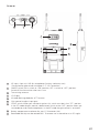
1.5 Frequency Transmission to Transmitter (ACT Function)
• The frequency of the receiver is transmitted to the appropriate transmitter via infrared.
• Press the ACT button to activate the ACT function. “ACT” is displayed.
• Hold the infrared diode of the switched on transmitter 20 cm at maximum in front of the
transmitting infrared diode of the receiver between the ACT and Scan button.
• The receiver displays “ACT” during the transmission.
• As soon as the transmitter displays the same frequency as the receiver, the transmission is finished.
The receiver displays the state before starting the frequency transmission.
Important:
In order to avoid interferences, the frequency of one receiver should be transmitted to one transmitter
only.
NE 911 NE 912 / 914
Infrared diode
Infrared diode

15
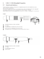
1.6 Connecting and Positioning of remote Antennae
In multichannel systems we recommend the use of the AT 70 A/B UHF antenna set consisting of
antennae, cables, antenna boosters and mounting kit.
1. Connect the receiving antennae to the corresponding antenna inputs and place the antennae to
the right and left of the receiver in the operating range where the transmitter is to be used. If
necessary change the position of the antennae to improve diversity reception.
2. The distance between the two receiving antennae should be at least 1 m.
3. The distance between transmitting and receiving antennae should be at least 3 m to avoid
overloading and interference between different channels. We therefore recommend installing the
antennae in a high position, especially in multi-channel systems.
4. If the operating range of the transmitters is
greater than the stage, the antennae can
be mounted vertically on the ceiling. The
distance between the two receiving
antennae should be approximately half the
total operating range.
Please note:
1. Install the receiving antennae in the same area as the transmitter.
2. To avoid interference do not install the antennae near digitally controlled components.
3. Keep a minimum distance of 0.5 m from metallic objects, including reinforced concrete walls or
pillars.
4. Do not bend the antenna cables at the antenna input, and ensure that they are not subjected to
undue stress.
> 1 m
> 3 m
> 1 m
AB
Stage
Auditorium
Operating range
Stage

16
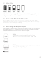
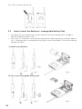
1.7 ZAS 900 Antenna Splitter
1.7.1 Controls and Indicators
(1) On/Off switch and power on LED. When the antenna splitter is switched on, the red
LED will illuminate.
(2) RF outputs to connect the receivers
(3) DC-connection to connect the DC power supply unit (12 V)
(4) Antenna sockets A/B. The antenna sockets provide a DC supply for antenna amplifiers.
(DC-Out: 8 V / 170 mA)
(5) Mounting brackets for 19" rack mounting
1.7.2 Installation
1. Mount the ZAS 900 antenna splitter and the receivers into a 19" rack by using the mounting
brackets.
2. Connect the supplied antennae to the antenna sockets A/B (4). You can also use optional remote
antennae. For mounting the antennae on the front use the supplied FB-30 mounting bracket.
3. Connect the receivers to the ZAS 900 antenna splitter with the supplied cables.
4. Connect the power supply unit to the DC-connection (3) and to AC power.
(Attention: Make sure that the indicated voltage corresponds to the local voltage.)
5. Switch on the ZAS 900 antenna splitter (1).
First receiver
Second receiver
Third receiver
Fourth receiver

17
1.7.3 General Information
1. The antenna sockets (4) feature a voltage of 8 V DC bias. To avoid a short circuit the sockets
must not touch the rack housing.
2. For the connection of remote antennae use usual 50Ω coaxial cables. The longer the cable, the
higher the RF signal loss. Therefore, the cable length should not exceed 6 m.
If you use longer cables, please use low-attenuation cables and if necessary antenna amplifiers.
3. Use 50Ω coaxial cables to connect the receivers to the ZAS 900 antenna splitter. The distance
between these devices should be as short as possible. We recommend using the supplied cables.
4. Supplied Accessories:
8 x RG 58 AU cables, 40 cm (TNC)
1 pair rack mount brackets supplied with antenna cables for front mounting
1 x 12 V / 500 mA power supply unit

18
1.8 Connection to a PC
The NE 911/912/914 receiver is fitted with an RJ 11 connector with an IN and OUT socket. In
order to operate several receivers with a PC they have to be connected as described below.
• Connect the OUT-socket of the first receiver (RX 1) with the IN-socket of the second receiver (RX 2),
connect the OUT-socket of the second receiver (RX 2) with the IN-socket of the third receiver (RX 3)
and so on.
• Connect the IN-socket of the first receiver (RX 1) to the converter.
• Connect the converter to the USB interface of the PC.
• By using the PC control software, 64 channels can be operated simultaneously at maximum.
• The distance between PC and receiver should not be too long, because to ensure high-speed
transmission the remote control cable should not be longer than 100 metres.
12
USB PORT
RJ 11

19
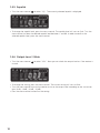
2. S 910 C / S 910 M Handheld Transmitter
2.1 Controls and Indicators
There are different condenser and dynamic microphone capsules for the handheld transmitter
(refer to Optional Accessories).
The S 910 C handheld transmitter has charging contacts and can be operated with the integrated
rechargeable battery pack only. For charging, the SLG 900 charger is available.
Avoid a direct contact of the charging contacts to the skin, as there is a voltage of 3 V at maximum.
Microphone capsule (can be unscrewed)
LC-Display
Infrared diode (at the bottom of the transmitter)
On/Off switch (at the bottom of the transmitter)
Charging contacts (at the bottom of the transmitter S 910 C only )
S 910 M
Microphone capsule (can be unscrewed)
LC-Display
Infrared diode (on the rear)
On/Off switch
1
2
3
4
1
2
3
4
5
S 910 C
1 2
3
4
5
1 2 43

20
2.2 How to insert the Batteries (S 910 M)
1. Unscrew the shaft of the S 910 M counter-clockwise.
2. Insert two 1.5 V batteries into the battery compartment observing polarity markings.
Note:
The S 910 C transmitter is powered by rechargeable batteries which cannot be changed by the user. If
the rechargeable batteries have to be changed, please contact your beyerdynamic dealer.
2.3 LC-Display
1. “ERR“ Message: When the “ERR“ message is displayed, there is an error.
ERR noo3: The frequency you want to program is above the switching bandwidth of the
transmitter. Use a receiver with an appropriate frequency group. (At this time the microphone is
still operating and the frequency remains unchanged. To clear the displayed “ERR“ message
switch off the handheld transmitter and on again.)
ERR noo4: The frequency you want to program is below the switching bandwidth of the
transmitter. Use a receiver with an appropriate frequency group. (At this time the microphone is
still operating and the frequency remains unchanged. To clear the displayed “ERR“ message
switch off the handheld transmitter and on again.)
2. “Group“ & “Channel“: When both indications are displayed, it means that you are using the
pre-programmed frequency of the receiver.
3. “Channel“: If “Channel“ is displayed only, it means that you are using a frequency which is not
pre-programed.
Page is loading ...
Page is loading ...
Page is loading ...
Page is loading ...
Page is loading ...
Page is loading ...
Page is loading ...
Page is loading ...
Page is loading ...
Page is loading ...
Page is loading ...
Page is loading ...
Page is loading ...
Page is loading ...
Page is loading ...
Page is loading ...
Page is loading ...
Page is loading ...
Page is loading ...
Page is loading ...
-
 1
1
-
 2
2
-
 3
3
-
 4
4
-
 5
5
-
 6
6
-
 7
7
-
 8
8
-
 9
9
-
 10
10
-
 11
11
-
 12
12
-
 13
13
-
 14
14
-
 15
15
-
 16
16
-
 17
17
-
 18
18
-
 19
19
-
 20
20
-
 21
21
-
 22
22
-
 23
23
-
 24
24
-
 25
25
-
 26
26
-
 27
27
-
 28
28
-
 29
29
-
 30
30
-
 31
31
-
 32
32
-
 33
33
-
 34
34
-
 35
35
-
 36
36
-
 37
37
-
 38
38
-
 39
39
-
 40
40


Beyerdynamic NE 914 User manual
- Category
- Supplementary music equipment
- Type
- User manual
Ask a question and I''ll find the answer in the document
Finding information in a document is now easier with AI
Related papers
-
Beyerdynamic NE 914 User manual
-
Beyerdynamic EM 981 S User manual
-
-
Beyerdynamic SEM 681 User manual
-
Beyerdynamic Opus 650 Set User manual
-
-
-
Beyerdynamic S 910 C User manual
-
-
Other documents
-
Shenzhen Yingbojingkong Technology ITC-308-WIFI User manual
-
Bosch PFN675T01/01 User manual
-
-
Pyle PDWM96 User manual
-
Soundmaster KCD46LI Datasheet
-
-
 PYLE Audio PDWM96 User manual
-
Pyle PDMW400HD User manual
-
JVC TN User manual
-
Citronic RU26H User manual
