Page is loading ...

2506 Galen Drive
Champaign, IL 61821
Voice 217.344.1243 • Fax 217.344.1245
www.cobaltdigital.com
OG-PC-X86A-OM (V1.0)
Cobalt Digital Inc.
Product Manual
Integral Frame-Installed PC for
openGear
®
Frames
OG-PC-x86-A
OG-PC-x86-A

Copyright
©Copyright 2019, Cobalt Digital Inc. All Rights Reserved.
Duplication or distribution of this manual and any information contained within is strictly prohibited without the express written
permission of Cobalt Digital Inc. This manual and any information contained within, may not be reproduced, distributed, or
transmitted in any form, or by any means, for any purpose, without the express written permission of Cobalt Digital Inc.
Reproduction or reverse engineering of software used in this device is prohibited.
Disclaimer
The information in this document has been carefully examined and is believed to be entirely reliable. However, no responsibility
is assumed for inaccuracies. Furthermore, Cobalt Digital Inc. reserves the right to make changes to any products herein to improve
readability, function, or design. Cobalt Digital Inc. does not assume any liability arising out of the application or use of any
product or circuit described herein.
Trademark Information
Cobalt
®
is a registered trademark of Cobalt Digital Inc.
openGear
®
is a registered trademark of Ross Video Limited. DashBoard™ is a trademark of Ross Video Limited.
Windows 10IoT and Windows 7 are trademarks of Microsoft Corporation. Windows products available in this product are
offered under license by MIcrosoft Corporation.
Intel
®
and Intel Pentium
®
are registered trademarks of Intel Corporation.
Loctite
®
is a registered tradename of Henkel Corporation.
Congratulations on choosing the Cobalt
®
OG-PC-X86-A Integral Frame-Installed PC for openGear
®
Frames.
The OG-PC-X86-A is part of a full line of modular processing and conversion gear for broadcast TV
environments. The Cobalt Digital Inc. line includes video decoders and encoders, audio embedders and de-
embedders, distribution amplifiers, format converters, remote control systems and much more. Should you
have questions pertaining to the installation or operation of your OG-PC-X86-A, please contact us at the
contact information on the front cover.
Manual No.: OG-PC-X86A-OM
Document Version: V1.0
Release Date: October 22, 2019
Description of
product/manual
changes:
- Initial release
OG-PC-X86A-OM (V1.0)

OG-PC-X86A-OM (V1.0) OG-PC-X86-A PRODUCT MANUAL i
Table of Contents
Chapter 1 Introduction . . . . . . . . . . . . . . . . . . . . . . . . . . . . . . . . . . . . . . . . . . . 1-1
Overview ................................................................................................................ 1-1
Manual Conventions............................................................................................... 1-2
Warnings, Cautions, and Notes .................................................................. 1-2
Labeling Symbol Definitions...................................................................... 1-2
Safety and Regulatory Summary............................................................................ 1-3
Warnings..................................................................................................... 1-3
Cautions...................................................................................................... 1-3
OG-PC-x86-A Functional Description................................................................... 1-3
Basic Processing Details............................................................................. 1-3
User Interface ............................................................................................. 1-4
HDD/SSD/OS Options............................................................................... 1-4
Technical Specifications......................................................................................... 1-5
Warranty and Service Information ......................................................................... 1-6
Cobalt Digital Inc. Limited Warranty......................................................... 1-6
Contact Cobalt Digital Inc...................................................................................... 1-7
Chapter 2 Installation . . . . . . . . . . . . . . . . . . . . . . . . . . . . . . . . . . . . . . . . . . . . 2-1
Overview ................................................................................................................ 2-1
Installing User-Added HDDs ................................................................................. 2-1
Installing Rear I/O Module..................................................................................... 2-3
Installing the OG-PC-x86-A Into Frame................................................................ 2-5
Rear I/O Module (Panel) Connections ................................................................... 2-6
Chapter 3 Setup Instructions. . . . . . . . . . . . . . . . . . . . . . . . . . . . . . . . . . . . . . . 3-1
Overview ................................................................................................................ 3-1
Accessing and Editing BIOS Settings.................................................................... 3-1
BIOS Main Menu ....................................................................................... 3-2
Advanced Menu.......................................................................................... 3-3
Saving and Exiting BIOS ........................................................................... 3-4
DashBoard Remote Control of OG-PC-x86-A....................................................... 3-5
In Case of Problems................................................................................................ 3-5

ii OG-PC-X86-A PRODUCT MANUAL OG-PC-X86A-OM (V1.0)
This page intentionally blank

OG-PC-X86A-OM (V1.0) OG-PC-X86-A PRODUCT MANUAL 1-1
Chapter 1
Chapter 1 Introduction
Overview
This manual provides installation and setup instructions for the OG-PC-x86-A
Integral Frame-Installed PC for openGear
®
Frames (also referred to herein as
the OG-PC-x86-A).
This manual consists of the following chapters:
• Chapter 1, “Introduction” – Provides information about this manual
and what is covered. Also provides general information regarding the
OG-PC-x86-A.
• Chapter 2, “Installation” – Provides instructions for installing the
OG-PC-x86-A in a frame, and connecting interfaces to the
OG-PC-x86-A.
• Chapter 3, “Setup Instructions” – Provides overviews of setup
instructions for setting up the OG-PC-x86-A to integrate within its
operating environment.
This chapter contains the following information:
• Manual Conventions (p. 1-2)
• Safety and Regulatory Summary (p. 1-3)
• OG-PC-x86-A Functional Description (p. 1-3)
• Technical Specifications (p. 1-5)
• Warranty and Service Information (p. 1-6)
• Contact Cobalt Digital Inc. (p. 1-7)

1 Manual Conventions
1-2 OG-PC-X86-A PRODUCT MANUAL OG-PC-X86A-OM (V1.0)
Manual Conventions
In this manual, the terms below are applicable as follows:
• OG-PC-x86-A refers to the OG-PC-x86-A Integral Frame-Installed
PC for openGear
®
Frames unit.
• Frame refers to the HPF-9000, oGx, oG3-FR, 8321, or similar
20-slot frame that houses Cobalt
®
or other cards.
• System and/or Video System refers to the mix of interconnected
production and terminal equipment in which the OG-PC-x86-A and
other cards operate.
• Functions and/or features that are available only as an option are
denoted in this manual like this:
Warnings, Cautions, and Notes
Certain items in this manual are highlighted by special messages. The
definitions are provided below.
Warnings
Warning messages indicate a possible hazard which, if not avoided, could
result in personal injury or death.
Cautions
Caution messages indicate a problem or incorrect practice which, if not
avoided, could result in improper operation or damage to the product.
Notes
Notes provide supplemental information to the accompanying text. Notes
typically precede the text to which they apply.
Labeling Symbol Definitions
Important note regarding product usage. Failure to observe may result in
unexpected or incorrect operation.
Electronic device or assembly is susceptible to damage from an ESD
event. Handle only using appropriate ESD prevention practices.
If ESD wrist strap is not available, handle only by edges and avoid
contact with any connectors or components.
Symbol (WEEE 2002/96/EC)
For product disposal, ensure the following:
• Do not dispose of this product as unsorted municipal waste.
• Collect this product separately.
• Use collection and return systems available to you.

OG-PC-X86A-OM (V1.0) OG-PC-X86-A PRODUCT MANUAL 1-3
Introduction Safety and Regulatory Summary
Safety and Regulatory Summary
Warnings
Cautions
OG-PC-x86-A Functional Description
Figure 1-1 shows a functional block diagram of the OG-PC-x86-A. The
OG-PC-x86-A Integral Frame-Installed PC for openGear
®
Frames is a
compact PC which is installed directly in the frame in the form of an
openGear-style card pair assembly with a double-width rear I/O module.
The OG-PC-x86-A obtains its power from the frame midplane with no
external cabling or sources. Using the OG-PC-x86-A, special applications of
the user’s choice can be conveniently collocated directly in the frame.
The OG-PC-x86-A unit installs in the same manner as any other openGear
®
device; the device/card is inserted into desired frame slot pair where it mates
with a rear I/O module. Via a rear I/O module supplied with the device,
OG-PC-x86-A external connections are provide, consisting of dual GigE,
USB 2.0 and 3.0, HDMI, serial, as well as a DisplayPort.
Note: A third, additional GigE port is available as a per-slot GigE connection when
OG-PC-x86-A is used in conjunction with the oGx frame or equivalent per-slot
GigE frame.
Basic Processing Details
The OG-PC-x86-A consists of the following architecture:
• Intel
®
Pentium
®
N3710
• 1.6 GHz (2.56 GHz burst)
• 4-Core
• 8GB DDR3
! WARNING !
To reduce risk of electric shock do not remove line voltage service barrier cover on frame
equipment containing an AC power supply. NO USER SERVICEABLE PARTS INSIDE.
REFER SERVICING TO QUALIFIED SERVICE PERSONNEL.
CAUTION
This device is intended for environmentally controlled use only in appropriate video
terminal equipment operating environments.
CAUTION
This device contains no user-serviceable components except where expressly stated.
Refer servicing to authorized personnel.

1 OG-PC-x86-A Functional Description
1-4 OG-PC-X86-A PRODUCT MANUAL OG-PC-X86A-OM (V1.0)
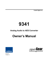
Figure 1-1 OG-PC-x86-A Functional Block Diagram
User Interface
Similar to a standard PC, the OG-PC-x86-A can provide user interface via its
USB ports (for mouse and keyboard) and its DisplayPort.
Hardware control features such as power on/off, reset, and sleep are
accessible on the device and via DashBoard remote control. This allows these
control functions to be accessed via DashBoard remote control with no need
for physical collocation to invoke hard reset or similar actions.
HDD/SSD/OS Options
The hardware/pre-loaded OS options listed below are available for the
OG-PC-x86-A. When ordered with a new OG-PC-x86-A unit, the option(s)
will be physically installed and ready for immediate use.
• -OG-PC-x86-HDD-1TB 1TB Hard Disk Drive for the OG-PC-x86-A
openGear
®
PC. (Two (2) max per OG-PC-x86-A unit)
• -OG-PC-x86-SSD-128GB 128GB M.2 Solid State Drive without
Operating System.
• -OG-PC-x86-SSD-128GB-WIN10IoT 128GB M.2 Solid State Drive with
Windows 10 IoT Operating System.
• -OG-PC-x86-SSD-128GB-WIN7 128GB M.2 Solid State Drive with
Windows 7 Embedded Operating System.
OG-PC-X86A BD V1.0LB142
Intel Pentium
N3710
OS SSD
(Note 1)
8GB DDR
HDD/RAID
Support
Rear I/O Module
User Ports
(3) GigE
(Note 2)
(2) USB 3.0
(2) USB 2.0
(1) HDMI
(1) RS-232
(1) DisplayPort
Notes:
1. Several SSD/OS options are available, including SSD without OS, or SSD
pre-loaded with various Windows OS options. Refer to text for more information.
2. Third GigE port (as connection to frame midplane) is available only in conjunction
with oGx frame or other frames offering per-slot GigE connectivity.
Power Interface
From Frame
Power

OG-PC-X86A-OM (V1.0) OG-PC-X86-A PRODUCT MANUAL 1-5
Introduction Technical Specifications
Technical Specifications
Table 1-1 lists the technical specifications for the OG-PC-x86-A Integral
Frame-Installed PC for openGear
®
Frames unit.
Table 1-1 Technical Specifications
Item Characteristic
Part number, nomenclature OG-PC-x86-A Integral Frame-Installed PC for openGear
®
Frames
Power Consumption Power Consumption (no RAID HDD options): 48.6 W
Power Consumption (RAID; 1 HDD; typ): 53.6 W
Power Consumption (RAID; 2 HDD; typ): 58.6 W
Power Management: ACPI
Battery: Lithium 3 V / 210 mAH
Note: Power figures below represent worse-case (all USB ports
fully loaded; HDDs (if equipped) spinning). Current draw is
distributed across multiple slots using supplied rear I/O
module. As such, per-slot power consumption is not
exceeded for supported 20-slot frames HPF-9000 and oGx
models.
Environmental:
Operational Temperature:
Operational Humidity:
Non-Operational Temperature:
Weight (including rear module):
0° to 45° C (32° to 113° F)
40° C (104° F) @ 95% RH Non-Condensing
-40° C to 85° C (-40° to 185° F)
0.57 kg (1.25 lb)
Frame Slot Physical Allocation Space 4 slots (unit in conjunction with Double-Wide rear I/O module)
Processor System CPU: Intel
®
Pentium
®
N3710
Base Frequency: 1.6 GHz (burst to 2.56 GHz)
Core Number: 4
BIOS: AMI UEFI 64 Mbit
For detailed information on the Intel
®
N3710 Processor used in this
product, please see Intel Pentium Processor N3710
Memory Technology: DDR3L 1600 MHz
Max. Capacity: 8GB
Storage 1x M.2 M-Key SATA (OS SSD specification defined by
order option)
2x HDD 2.5in SATA
Display Intel
®
HD Graphics 505
HDMI: 1.4b up to 3840 x 2160 at 30 Hz
DisplayPort: 1.1a up to 3840 x 2160 at 30 Hz
Ethernet Speed: 10/100/1000 Mbps
Connectors: (2) RJ45 on rear I/O panel

1 Warranty and Service Information
1-6 OG-PC-X86-A PRODUCT MANUAL OG-PC-X86A-OM (V1.0)
Warranty and Service Information
Cobalt Digital Inc. Limited Warranty
This product is warranted to be free from defects in material and workmanship for a period of one (1)
year from the date of shipment to the original purchaser.
Cobalt Digital Inc.'s (“Cobalt”) sole obligation under this warranty shall be limited to, at its option, (i)
the repair or (ii) replacement of the product, and the determination of whether a defect is covered under
this limited warranty shall be made at the sole discretion of Cobalt.
This limited warranty applies only to the original end-purchaser of the product, and is not assignable or
transferrable therefrom. This warranty is limited to defects in material and workmanship, and shall not
apply to acts of God, accidents, or negligence on behalf of the purchaser, and shall be voided upon the
misuse, abuse, alteration, or modification of the product. Only Cobalt authorized factory
representatives are authorized to make repairs to the product, and any unauthorized attempt to repair
this product shall immediately void the warranty. Please contact Cobalt Technical Support for more
information.
To facilitate the resolution of warranty related issues, Cobalt recommends registering the product by
completing and returning a product registration form. In the event of a warrantable defect, the
purchaser shall notify Cobalt with a description of the problem, and Cobalt shall provide the purchaser
with a Return Material Authorization (“RMA”). For return, defective products should be double boxed,
and sufficiently protected, in the original packaging, or equivalent, and shipped to the Cobalt Factory
Service Center, postage prepaid and insured for the purchase price. The purchaser should include the
RMA number, description of the problem encountered, date purchased, name of dealer purchased
from, and serial number with the shipment.
Cobalt Digital Inc. Factory Service Center
2506 Galen Drive Office: (217) 344-1243
Champaign, IL 61821 USA Fax: (217) 344-1245
www.cobaltdigital.com Email: info@cobaltdigital.com
THIS LIMITED WARRANTY IS EXPRESSLY IN LIEU OF ALL OTHER WARRANTIES
EXPRESSED OR IMPLIED, INCLUDING THE WARRANTIES OF MERCHANTABILITY AND
FITNESS FOR A PARTICULAR PURPOSE AND OF ALL OTHER OBLIGATIONS OR
LIABILITIES ON COBALT'S PART. ANY SOFTWARE PROVIDED WITH, OR FOR USE WITH,
THE PRODUCT IS PROVIDED “AS IS.” THE BUYER OF THE PRODUCT ACKNOWLEDGES
THAT NO OTHER REPRESENTATIONS WERE MADE OR RELIED UPON WITH RESPECT TO
THE QUALITY AND FUNCTION OF THE GOODS HEREIN SOLD. COBALT PRODUCTS ARE
NOT AUTHORIZED FOR USE IN LIFE SUPPORT APPLICATIONS.
COBALT'S LIABILITY, WHETHER IN CONTRACT, TORT, WARRANTY, OR OTHERWISE, IS
LIMITED TO THE REPAIR OR REPLACEMENT, AT ITS OPTION, OF ANY DEFECTIVE
PRODUCT, AND SHALL IN NO EVENT INCLUDE SPECIAL, INDIRECT, INCIDENTAL, OR
CONSEQUENTIAL DAMAGES (INCLUDING LOST PROFITS), EVEN IF IT HAS BEEN
ADVISED OF THE POSSIBILITY OF SUCH DAMAGES.

OG-PC-X86A-OM (V1.0) OG-PC-X86-A PRODUCT MANUAL 1-7
Introduction Contact Cobalt Digital Inc.
Contact Cobalt Digital Inc.
Feel free to contact our thorough and professional support representatives for
any of the following:
• Name and address of your local dealer
• Product information and pricing
• Technical support
• Upcoming trade show information
Phone: (217) 344-1243
Fax: (217) 344-1245
Web: www.cobaltdigital.com
General Information: info@cobaltdigital.com
Technical Support: support@cobaltdigital.com

1-8 OG-PC-X86-A PRODUCT MANUAL OG-PC-X86A-OM (V1.0)
This page intentionally blank

OG-PC-X86A-OM (V1.0) OG-PC-X86-A PRODUCT MANUAL 2-1
Chapter 2
Chapter 2 Installation
Overview
This chapter provides steps for physical installation and pre-power-up setup of
the OG-PC-x86-A as follows:
• Installing User-Added HDDs (p. 2-1)
• Installing Rear I/O Module (p. 2-3)
• Installing the OG-PC-x86-A Into Frame (p. 2-5)
• Rear I/O Module (Panel) Connections (p. 2-6)
Installing User-Added HDDs
Note: This procedure is applicable only if user-added HDD(s) are to be added in a
fielded OG-PC-x86-A. For factory-installed time-of-purchase options (see
HDD/SSD/OS Options (see p. 1-4 in Chapter 1, Introduction), no field
installation is needed.
CAUTION
This device contains semiconductor devices which are
susceptible to serious damage from Electrostatic
Discharge (ESD). ESD damage may not be immediately
apparent and can affect the long-term reliability of the
device.
Avoid handling circuit boards in high static environments
such as carpeted areas, and when wearing synthetic fiber
clothing. Always use proper ESD handling precautions
and equipment when working on circuit boards and
related equipment.
When disassembling to access HDD mounting area, the
OG-PC-x86-A component side of PCB will be positioned
against work surface. Make certain surface is prepped with
soft anti-static material to avoid damaging or dislodging
surface-mount components.

2 Installing User-Added HDDs
2-2 OG-PC-X86-A PRODUCT MANUAL OG-PC-X86A-OM (V1.0)
Figure 2-1 HDD Mounting Area and Details
1.
(See Figure 2-1) Around periphery of OG-PC-x86-A assembly, remove
six (6) screws securing HD Piggyback Board (HDD mounting PCB)
from OG-PC main board. Tilt HD Piggyback Board away from main
PCB.
CAUTION
When installing HDD(s), avoid allowing HDD case from contacting
surface-mount components on OG-PC main PCB. Components can be
damaged if HDD case strikes component(s).
2.
Prep threads of each of four (4) HDD securing screws (supplied with
HDD) with a small drop of blue threadlock compound (Loctite
®
243 or
equivalent).
3. Secure HDD to HD Piggyback Board using four (4) screws supplied
with HDD.
4. Position HDD (along with piggyback PCB) to align with its interconnect
cable. Connect interconnect cable to HDD.
5. Repeat steps 2 thru 4 for second HDD (if used).
6. Prep threads of each of six (6) HD Piggyback Board securing screws
with a small drop of blue threadlock compound (Loctite
®
243 or
equivalent).
HDD Mounting PCB (HD Piggyback Board)
(Shown separated from Main PCB)
HDD Mounting Areas
(each with 4 mounting screw holes)
(6) HDD Mounting PCB
Mounting Standoffs

OG-PC-X86A-OM (V1.0) OG-PC-X86-A PRODUCT MANUAL 2-3
Installation Installing Rear I/O Module
CAUTION
Make certain HD Piggyback Board power harness leads are positioned around
standoff and not pinched between standoff and piggyback PCB.
7.
Carefully align HD Piggyback Board in mounting position on the six (6)
peripheral mounting standoffs. Start six (6) securing screws.
8. Fully tighten six (6) HD Piggyback Board securing screws.
Installing Rear I/O Module
CAUTION
Make certain Rear I/O Module is installed before installing the OG-PC-x86-A
into the frame slot. Damage to card and/or Rear I/O Module can occur if
module installation is attempted with card already installed in slot.
The Rear I/O Module provides the user “rear panel” connection breakouts for
the OG-PC-x86-A assembly. Install Rear I/O Module as follows:
1. On the frame, determine the slot in which the OG-PC-x86-A is to be
installed.
Note: Although an OG-PC-x86-A can be installed anywhere in the frame, typically it
is recommended to select a group of slots at the left-most or right-most of
available slots. The OG-PC-x86-A and its mating rear I/O module will require
four (4) slots (example: OG-PC-x86-A and rear I/O module positioned to use
slots 17 thru 20 in the 20-slot frame).
2. In the mounting area corresponding to the slot location, install
Rear I/O Module as shown in Figure 2-2.

2 Installing Rear I/O Module
2-4 OG-PC-X86-A PRODUCT MANUAL OG-PC-X86A-OM (V1.0)
Figure 2-2 Rear I/O Module Installation
Align and engage mounting tabs on Rear
I/O Module with the module seating slots
on rear of frame chassis.
Hold top of Rear I/O Module flush against frame chassis and start the
captive screws. Lightly tighten each captive screw.
Note: Screws are captive retained on unmounted Rear I/O Module
using O-rings. Pushing the screws backwards into the O-rings
(allowing only a few threads to protrude in front of O-rings)
allows the screws to more easily thread into the chassis
threaded holes.
1
2

OG-PC-X86A-OM (V1.0) OG-PC-X86-A PRODUCT MANUAL 2-5
Installation Installing the OG-PC-x86-A Into Frame
Installing the OG-PC-x86-A Into Frame
CAUTION
Heat and power distribution requirements within a frame may dictate specific
slot placement of cards. Cards with many heat-producing components should
be arranged to avoid areas of excess heat build-up, particularly in frames
using only convection cooling. The OG-PC-x86-A has a high power
dissipation of up to 60 W. As such, avoiding placing the device adjacent to
other devices/cards with similar dissipation values if possible. Also, frame
power budget must be considered if multiple OG-PC-x86-A devices are to be
installed, or other devices/cards are to be collocated in the same frame.
CAUTION
CAUTION
Make certain Rear I/O Module supplied with the OG-PC-x86-A is installed
before
installing the OG-PC-x86-A into the frame slot. Damage to device and/
or Rear I/O Module can occur if module installation is attempted with device
already installed in slot.
Install the OG-PC-x86-A into a frame slot as follows:
1. Open the frame front access panel.
2. Noting the four slots occupied by the rear I/O module, determine the
slots in which the OG-PC-x86-A will mate with the rear I/O module.
3. While holding the OG-PC-x86-A assembly by its front edges, align the
assembly such that the plastic ejector tabs are on the bottom.
4. Insert the OG-PC-x86-A such that its card-edge connector on rear of
assembly is aligning with corresponding female connector on its rear I/O
module, aligning the assembly with the top and bottom guides of the
slots in which the assembly is being installed.
5. When certain assembly is aligning with connector on rear I/O
module, gradually slide the assembly into the slot. When resistance is
noticed, gently continue pushing the assembly until its rear printed
circuit edge terminals engage fully into the rear I/O module mating
connector.
This device contains semiconductor devices which are
susceptible to serious damage from Electrostatic
Discharge (ESD). ESD damage may not be immediately
apparent and can affect the long-term reliability of the
device.
Avoid handling circuit boards in high static environments
such as carpeted areas, and when wearing synthetic fiber
clothing. Always use proper ESD handling precautions
and equipment when working on circuit boards and
related equipment.

2 Rear I/O Module (Panel) Connections
2-6 OG-PC-X86-A PRODUCT MANUAL OG-PC-X86A-OM (V1.0)
CAUTION
If assembly resists fully engaging in rear I/O module mating connector, check
for alignment and proper insertion in slot tracks. Damage to assembly and/or
rear I/O module may occur if improper insertion is attempted.
6.
Verify that the assembly is fully engaged in rear I/O module mating
connector.
7. Close the frame front access panel.
8. Connect cabling as shown in Rear I/O Module (Panel)
Connections (p 2-6).
Note: To remove the assembly, press down on the ejector tabs to unseat the
assembly from the rear I/O module mating connector. Evenly draw the
assembly from its slots.
Rear I/O Module (Panel) Connections
Perform rear I/O module panel cable connections as shown in Figure 2-3.
Figure 2-3 OG-PC-x86-A Rear I/O Module Panel Connectors
Connector Function
GigE Two (2) GIgE Ethernet RJ-45 ports for OG-PC-x86-A network connections
USB 2.0 Two (2) USB 2.0 ports (Standard connector type)
USB 3.0 Two (2) USB 3.0 ports (Standard connector type)
HDMI One (1) HDMI port (Type A connector)
DP1.1a One (1) DisplayPort connector (DP1.1a)
RS-232 One (1) RS-232 COMM port (Dsub-9(F) connector
OG-PC-x86-A Rear Panel

OG-PC-X86A-OM (V1.0) OG-PC-X86-A PRODUCT MANUAL 3-1
Chapter 3
Chapter 3 Setup Instructions
Overview
This chapter contains the following information:
• Accessing and Editing BIOS Settings (p. 3-1)
• DashBoard Remote Control of OG-PC-x86-A (p. 3-5)
• In Case of Problems (p. 3-5)
Note: All instructions here assume OG-PC-x86-A is physically installed in a powered
20-slot frame and interconnected to user interface assets as described in
Chapter 2. Installation.
Accessing and Editing BIOS Settings
Figures 3-1 thru 3-3 show the AMI BIOS used on the PC module within the
OG-PC-x86-A. Using the BIOS Setup Utility shown, BIOS settings can be
modified as desired.
Note: Some menus are available from the BIOS Main menu but are not described
here. Many of the functions within these tabs are pre-configured to adapt the
PC module to conform with specified OG-PC-x86-A functionality and should
not be modified. If changes or more information regarding these functions are
desired, contact Cobalt Digital for assistance and further information.

3 Accessing and Editing BIOS Settings
3-2 OG-PC-X86-A PRODUCT MANUAL OG-PC-X86A-OM (V1.0)
BIOS Main Menu
The BIOS Main menu provides access to basic setup functions such as date
and language, and also provides access to other menus such as Advanced and
specific configuration menus.
Figure 3-1 BIOS Main Setup Screen
With OG-PC-x86-A in powered-up frame, press <F2> or <DEL> to enter the Main Setup menu (shown below).
When in the Main menu, other menus can be accessed. The Main tab is always accessible from other menus for returning to the Main
menu.
The Main BIOS setup screen has two main frames. The left frame displays all the options that can be configured. Grayed-out options
cannot be configured; options in blue can be configured. The right frame displays the key legend. Above the key legend is an area re-
served for a text message. When an option is selected in the left frame, it is highlighted in white. Often a text message will accompany
the selected item.
/