Vicon SN240D Quick start guide
- Category
- Security cameras
- Type
- Quick start guide

SN240D PTZ Dome Camera
Quick Guide
XX305-20-01
Vicon Industries Inc.
Tel: 631-952-2288) Fax: 631-951-2288
Toll Free: 800-645-9116
24-Hour Technical Support: 800-34-VICON
(800-348-4266) UK: 44/(0) 1489-566300
www.vicon-security.com
Vicon Industries Inc. does not warrant that the functions contained in this equipment
will meet your requirements or that the operation will be entirely error free or perform
precisely as described in the documentation. This system has not been designed to be
used in life-critical situations and must not be used for this purpose.
Document Number: 8009-8305-20-01 Product specifications subject to change without
notice. Issued: 2/20 Copyright © 2020 Vicon Industries Inc. All rights reserved.

2
1 Introduction
The SN240D high-definition (HD) PTZ dome camera is designed to fit in a wide range of
environments. The 4.3-129 mm varifocal lens with an optical 30X zoom provides superb sharpness
and excellent sensitivity. The day/night camera is utilizes a 1/2.8” CMOS sensor, which can
provide quality imaging down to 0.013 lux. True Wide Dynamic Range (WDR; 120dB) improves
detail in bright or low light areas of the image and DNR corrects imperfections in the image.
1.1 Components
This system comes with the following components;
* Dome Camera 1
* Installation Guide 1
* Accessory Kit & Connector 1
1) Torx wrench (1)
2) 2-Pin Terminal Block (1)
3) 3-Pin Terminal Block (2)
4) 6-Pin Terminal Block (1)
* RJ-45 Waterproof Cover 1
* Install Adaptor 1

3
1.2 Key Features
• Brilliant video quality
The network camera offers the highly efficient H.264 video compression, which drastically
reduces bandwidth and storage requirements without compromising image quality. Motion JPEG
is also supported for increased flexibility.
• Dual or Triple Streams
The network camera can deliver dual or triple video streams simultaneously at full frame rate in
all resolutions up to Full-HD (1920 x 1080p) using H.264 and Motion JPEG. This means that
several video streams can be configured with different compression formats, resolutions and
frame rates for different needs.
• Image setting adjustment
The network camera also enables users to adjust image settings such as contrast, brightness
and saturation to improve images before encoding takes place.
• Intelligent video capabilities
The network camera includes intelligent capabilities such as VCA (Video Content Analysis). The
network camera’s external inputs and outputs can be connected to devices such as sensors and
relays, enabling the system to react to alarms and activate lights or open/close doors.
• Improved Security
The network camera logs all user access, and lists currently connected users. Also, its full frame
rate video can be provided over HTTPS.
• PoE (Power over Ethernet)
This network camera can be powered through PoE, which simplifies installation since only one
cable is needed for carrying power, as well as video controls.
• ONVIF Certificate
This is a global interface standard that makes it easier for end users, integrators, consultants,
and manufacturers to take advantage of the possibilities offered by network video technology.
ONVIF enables interoperability between different vendor products, increased flexibility, reduced
cost, and future-proof systems.
• Micro-SD Recording support
The network camera also supports a Micro-SD memory slot for local recording with removable
storage.
• Audio support
The network camera also supports two-way audio.

4
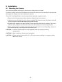
2 Installation
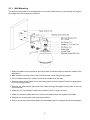
2.1 Mounting the Camera
You need one optional mounting kit, wall mount or ceiling mount, to install.
The wall or ceiling mount must be attached to a structural object such as hard wood, concrete that
will support the weight of the mount and dome camera.
The use of a solid backboard is recommended when attaching to gypsum walls.
1. Remove the Protection pad and the tape from attached the dome camera.
2. Attach the mounting base to wall using the supplied M8 tapping screw and plastic bushing.
(Ceiling using the supplied M6 tapping screw and bushing)
3. Wind the both thread of the pipe end with Teflon tape about 20 times for sealing. Then use a
silicone rubber sealant to seal the area where the wall (ceiling) mount and the pipe meet.
4. Place a bead of silicone sealant around the wall and ceiling mount mounting flange, press it to
the surface and line up the flange hole with drilled holes.
CAUTION 1: A silicone rubber sealant must be applied to seal the housing to secure
waterproofing.
CAUTION 2: When installing, a bracket must be applied.
CAUTION 3: Please reset the camera after 30 ~ 60 minutes when installing it in situations colder
than 14° F (-10°C).

5
2.1.1 Wall Mounting
The wall mounting plate must be attached to a structural object such as concrete that will support
the weight of the mount and dome camera.
1. Select a suitable mounting location and verify there is sufficient cable to reach the middle of the
Wall Mount.
2. Mark and drill mounting holes in the surface the wall mount flange as a template.
3. Pull out cables required to connect to the dome camera from the wall.
4. Secure the wall mount bracket to the wall using plastic anchors and 8x35 screws or appropriate
for the mounting surface.
5. Remove the cable access plate and route cables through rectangular access hole of the wall
mount bracket.
6. Attach the 1.5 inch adapter to wall mount bracket and fix it using set screw.
7. Attach the camera’s safety wire to the wall mount bracket latch and organize the cables.
8. Reattach the access plate of the wall mount bracket.
9. Push in and turn the camera clockwise into the adapter and fix it using set screw of the adapter.

6
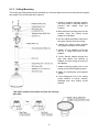
2.1.2 Ceiling Mounting
The ceiling mounting plate must be attached to a structural object such as concrete that will support
the weight of the mount and dome camera.
This figure shows how to twist and lock the housing
with pipe.
1. Select a suitable mounting location
and verify there is sufficient cable to
connect with cables from the
housing.
2. Mark and drill mounting holes on the
surface using the ceiling mount
flange as a template.
3. Pull out cables required to connect to
the dome camera from the ceiling.
4. Attach the ceiling mount bracket
using plastic anchors and screws.
5. Attach 1.5 inch adapter to the pipe
and fix it using set screw of the
adapter.
6. Route camera cables through the
pipe and attach the camera to
adapter; fix them using set screw of
the adapter.
7. Attach housing’s safety wire to the
ceiling mount’s 6x35 tapping screw.
8. Make all connections and organize
cables.
9. Lock hexagonal nut of the ceiling
mount bracket to secure camera,
attached pipe and ceiling mount
bracket.

7
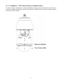
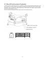
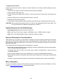
2.1.3 Installation – PTZ Camera Remove for Maintenance
In order to perform maintenance or change hardware settings, remove lower dome cover first
and
unlock the camera assembly by turning in the direction indicated by the arrows in the
figure below
to remove the PTZ camera.

8
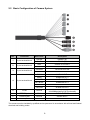
2.2 Basic Configuration of Camera System
No.
Connector
Wire Color
Description
1
2-pin terminal block
GREEN
RS485+ (A)
BLUE
RS485- (B)
2
3-pin terminal block
RED
24 VAC or 12 VDC+
WHITE
24 VAC or 12 VDC-
3
3-pin terminal block
ORANGE
HEATER and FAN
BLACK
HEATER and FAN
4
6-pin terminal block
PINK
ALARM INPUT 1
GRAY
ALARM INPUT 2
VIOLET
ALARM INPUT 3
SKY BLUE
ALARM INPUT 4
BROWN
GND
YELLOW
ALARM OUTPUT
5
RJ-45
BLACK
Ethernet, RJ-45 port compatible with
10/100Mbps having PoE functionality
6
STEREO jack
GRAY
AUDIO OUTPUT
7
STEREO jack
BLACK
AUDIO INPUT
8
BNC jack
BLACK
CVBS OUTPUT
The camera must be installed by qualified service personnel in accordance with all local and federal
electrical and building codes.

9
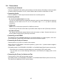
2.3 Micro-SD Card Insertion & Termination
The device that is connected at end of line, whether it is a dome camera or keyboard controller, must
have the cable for communication terminated by setting the appropriate DIP switch. Without proper
termination, there is potential for control signal errors. Total length of the cable for communication
should not exceed 4000 ft (1.2 km).
User can install and change Micro-SD card as shown in the following picture.
SW1
1
Terminated
ON
Not terminated
OFF

10
2.4 Connections
• Connecting the Network
Connect a standard RJ-45 cable to the network port of the camera. Generally a crossover cable
is used for direct connection to a PC, while a direct cable is used for connection to a hub.
• Connecting Audio
Connect speaker to audio output line and external mic to audio input line.
• Connecting Alarms
– A1, A2, A3, A4 (Alarm Input 1, 2, 3, 4)
You can use external devices to signal the camera to react on events. Mechanical or electrical
switches can be wired to the A1, A2, A3, A4 (Alarm Input 1, 2, 3, 4) and G (Ground)
connectors.
– G (Ground)
NOTE: All the connectors marked G or GND are common.
Connect the ground side of the alarm input and/or alarm output to the G (Ground) connector.
– AO (Alarm Output)
The camera can activate external devices such as buzzers or lights. Connect the device to
the AO (Alarm Output) and G (Ground) connectors.
• Connecting to the RS485
The camera can be controlled remotely by an external device or control system, such as a
control keyboard, using RS485 half-duplex serial communications signals.
• Connecting the Power of Camera
Connect power of 12 VDC or 24 VAC for the camera.
When using a 12 VDC adapter, connect the positive (+) pole to the ‘+’ position and the negative
(-) pole to the ‘-’ position.
Use satisfy clause 2.5 of IEC60950-1/UL60950-1 or Certified/Listed Class 2 power source only.
– Be careful not to reverse the polarity when you connect the12 VDC power cable.
– You can also use a router featuring PoE (Power over Ethernet) to supply power to the
camera.
• Connecting the Power for Heater and Fan
Connect power of 24 VAC for the heater and fan.
Use satisfy clause 2.5 of IEC60950-1/UL60950-1 or Certified/Listed Class 2 power source only.
This requires an additional 24 VAC power supply.

11
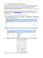
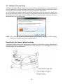
2.4.1 Network Connection & IP Assignment
The network camera is designed for use on an Ethernet network and requires an IP address for
access. Most networks today have a DHCP server that automatically assigns IP addresses to
connected devices. By the factory default, your camera is set to obtain the IP address
automatically via DHCP server. If your network does not have a DHCP server the network camera
will use 192.168.1.100 as the default IP address.
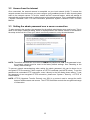
If DHCP is enabled and the product cannot be accessed, run the SmartManager utility, which can
be found on Vicon’s website, vicon-security.com under Software Downloads, to search and
allocate an IP address, or reset the product to the factory default settings and then perform the
installation again.
1) Connect the network camera/device to the network and power up.
2) Start SmartManager utility (Start > All programs > SmartManager > SmartManager).
The main window will display, and after a short while any network devices connected to the
network will be displayed in the list.
3) Select the camera on the list and click right button of the mouse. A pop-up menu will display as
below.
4) Select Assign IP Address. The Assign IP window will display. Enter the required IP address.
NOTE: For more information, refer to the SmartManager User’s Manual.

12
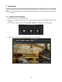
3 Operation
The network camera can be used with Windows operating system and browsers. The recommended
browsers are Internet Explorer®, Safari®, Firefox®, Opera® and Google® Chrome® with Windows.
NOTE: To view streaming video in Microsoft® Internet Explorer, set your browser to allow ActiveX
controls.
3.1 Access from a browser
1. Start a browser (ex., Internet Explorer).
2. Enter the IP address or host name of the network camera in the Location/Address field of your
browser.
3. You can see a starting page. Click Live View, Playback, or Setup to enter web page.
4. The network camera’s Live View page appears in your browser.

13
3.2 Access from the internet
Once connected, the network camera is accessible on your local network (LAN). To access the
network camera from the Internet you must configure your broadband router to allow incoming data
traffic to the network camera. To do this, enable the NAT traversal feature, which will attempt to
automatically configure the router to allow access to the network camera. This is enabled from Setup
> System > Network > NAT. For more information, please see “System > Network > NAT” of User’s
Manual.
3.3 Setting the admin password over a secure connection
To gain access to the product, the password for the default administrator user must be set. This is
done in the Admin Password dialog, which is displayed when the network camera is accessed for
the setup at the first time. Enter your admin name and password, set by the administrator.
NOTE: The default administrator user name is ADMIN and password is 1234. If the password is lost,
the network camera must be reset to the factory default settings. See “Resetting to the
factory default settings”.
To prevent network eavesdropping when setting the admin password, this can be done via an
encrypted HTTPS connection, which requires an HTTPS certificate (see NOTE below). To set the
password via a standard HTTP connection, enter it directly in the first dialog shown above. To set
the password via an encrypted HTTPS connection, please see “System > Security > HTTPS” of
User’s Manual.
NOTE: HTTPS (Hypertext Transfer Protocol over SSL) is a protocol used to encrypt the traffic
between web browsers and servers. The HTTPS certificate controls the encrypted exchange
of information.

14
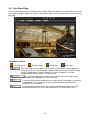
3.4 Live View Page
The Live View page comes in several screen modes. Users can select the most suitable one out of
the modes provided. Adjust the mode in accordance with your PC specifications and monitoring
purposes.
1) General controls
Live View Page Playback Page Setup Page Help Page
The video drop-down list allows you to select a customized or preprogrammed
video stream on the Live View page. Stream profiles are configured under Setup
> Basic Configuration > Video & Image. For more information, see “Basic
Configuration > Video & Image” of User Manual.
The resolution drop-down list allows you to select the most suitable video
resolution to be displayed on Live View page.
The protocol drop-down list allows you to select which combination of protocols
and methods to use depending on your viewing requirements and on the
properties of your network.
The preset drop-down list allows you to select the preset number for the PTZ
camera being used. This icon is inactivated if the PTZ settings are not set.

15
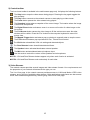
2) Control toolbar
The live viewer toolbar is available in the web browser page only. It displays the following buttons:
The Stop button stops the video stream being played. Pressing the key again toggles the
play and stop.
The Play button connects to the network camera or starts playing a video stream.
The Pause button pauses the video stream being played.
The Snapshot button takes a snapshot of the current image. The location where the image
is saved can be specified.
The Digital Zoom button activates a zoom-in or zoom-out function for video image on the
live screen.
The Full Screen button causes the video image to fill the entire screen area. No other
windows will be visible. Press the ’Esc’ button on the computer keyboard to cancel full
screen view.
The Manual Trigger button activates a pop-up window to manually start or stop the event.
The PTZ button activates a pop-up window for Pan, Tilt and Zoom control.
The VCA button shows/hides VCA rule setting and detected objects.
The Face Detector button shows/hides detected faces.
The Speaker button activates/deactivates external speaker.
The Mic button activates/deactivates microphone input.
Use this scale to control the volume of the speakers and microphones.
NOTE 1: VCA and Face Detector buttons appear only when each function is activated.
NOTE 2: VCA and Face Detector work exclusively of each other.
3) Video Streams
The network camera provides several images and video stream formats. Your requirements and
the properties of your network will determine the type you use.
The Live View page in the network camera provides access to H.264 and Motion JPEG video
streams, and to the list of available video streams. Other applications and clients can also access
these video streams/images directly, without going via the Live View page.

16
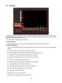
3.5 Playback
The Playback window contains a list of recordings made to the memory card. It shows each
recording’s start time, length, the event type used to start the recording, calendar and time slice bar
indicates if the recording exists or not.
The description of playback window follows.
1) Video Screen
You can see the video screen when playing the video clip in the Micro SD memory.
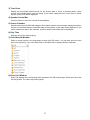
2) Playback Buttons
To view a recording data in the SD local storage, select it from the list and click the Playback
buttons.
Go to the first: go to the beginning of the video clip.
Fast backward play: fast play backward (rewind) of the video clip.
Backward play: play backward (rewind) of the video clip.
Step backward play: go back one frame of the video clip.
Pause: pause playback of the video clip.
Step forward play: go forward one frame of the video clip.
Forward Play: play forward the video clip.
Fast forward play: play fast forward of the video clip.
Go to the last: go to the end of the video clip.
Clip copy: copy the video clip.
Zoom In: zoom in the video clip.
Full Screen: display full screen of the video.

17
3) Time Chart
Display an hour-based search screen for the chosen date. If there is recording data, a blue
section will be displayed on a 24-hour basis. If you select a particular hour in the chart, a yellow
square on the hour will be displayed.
4) Speaker Control Bar
Use this scale to control the volume of the speakers.
5) Search Calendar
Search results from the SD local storage in the network camera connected are displayed monthly.
If there is a recorded data for a particular date, a blue square on the date will be displayed. If you
select a particular date in the calendar, a yellow square on the date will be displayed.
6) Play Time
Displays time of the video playing.
7) Event Search Window
Select a search option in the drop-down list and click GO button. You can also enter the time
period for searching. If you click Start Date or End Date zone, displays Search Calendar.
8) Event List Window
Event List displays the event(s) that were recorded in the SD local storage. Select a list and click
the play button. The video clip will be played.

18
3.6 Network Camera Setup
This section describes how to configure the network camera. Administrator has unrestricted access
to all the Setup tools, whereas Operators have access to the settings of Basic Configuration, which
are Live View, Video & Image, Audio, Event, Dome Configuration, and System.
You can configure the network camera by clicking Setup either in the first connection page or the
top second-right button of the Live View page. Accessing the network camera from a computer for
the first time opens the Admin Password dialog box. Enter your administrator or operator user name
and password to get into setup page.
NOTE: If the password is lost, the network camera must be reset to the factory default settings.
Please see “Resetting to the factory default setting”.
Resetting to the factory default settings
To reset the network camera to the original factory settings, go to the Setup > System > Maintenance
web page (described in “System > Maintenance” of User’s Manual) or use the Reset button on the
network camera, as described below:

19
• Using the Reset button:
Follow the instructions below to reset the network camera to the factory default settings using the
Reset button.
1. Switch off the network camera by disconnecting the power adapter.
2. Open the Micro-SD card cover.
3. Press and hold the Reset button (SW1) on the board with your finger while reconnecting the
power.
4. Keep the Reset button (SW1) pressed for about 2 seconds.
5. Release the Reset button (SW1).
6. The network camera resets to factory defaults and restarts after completing the factory reset.
CAUTION: When performing a Factory Reset, you will lose any settings that have been saved. (The
unit now obtains the IP address automatically via DHCP.)
System Requirement for Web Browser
• Operating System: Microsoft Windows OS Series
• CPU: Intel Core 2 Duo 2GHz or higher, 1GB RAM or more, 10GB free disk or higher
• VGA: AGP, Video RAM 32MB or higher (1024x768, 24bpp or higher)
General Performance Considerations
When setting up your system, it is important to consider how various settings and situations will affect
performance. Some factors affect the amount of bandwidth (the bit rate) required, others can affect
the frame rate, and some affect both. If the load on the CPU reaches its maximum, this will also
affect the frame rate.
The following factors are among the most important to consider:
• High image resolutions and/or lower compression levels (or high bitrates) result in larger images.
Frame rate and Bandwidth affected.
• Accessing both Motion JPEG and H.264 video streams simultaneously. Frame rate and
bandwidth affected.
• Heavy network utilization due to poor infrastructure. Frame rate and Bandwidth affected.
• Heavy network utilization via wireless router due to poor infrastructure. Frame rate and bandwidth
affected.
• Viewing on poorly performing client PCs lowers perceived performance. Frame rate affected.
More Information
For more information, please see the network camera User’s Manual, which is available on Vicon’s
website, www.vicon-security.com, under Documentation.

Full-HD NETWORK SPEED DOME CAMERA
50304029B
-
 1
1
-
 2
2
-
 3
3
-
 4
4
-
 5
5
-
 6
6
-
 7
7
-
 8
8
-
 9
9
-
 10
10
-
 11
11
-
 12
12
-
 13
13
-
 14
14
-
 15
15
-
 16
16
-
 17
17
-
 18
18
-
 19
19
-
 20
20


Vicon SN240D Quick start guide
- Category
- Security cameras
- Type
- Quick start guide
Ask a question and I''ll find the answer in the document
Finding information in a document is now easier with AI
Related papers
-
Vicon SN240D Operating instructions
-
-
-
-
-
-
-
-
-
Other documents
-
Costar CBI4H36IW Owner's manual
-
Vista VK2-108VRDIR35V16e Quick Manual
-
-
-
-
Eneo NXD-2012PTZ1080 B User manual
-
-
Costar CDJBD360 Owner's manual
-
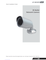 Syscom Video IR Bullet Network Camera Quick Installation Manual
-
