Page is loading ...

ENCODER PARTS AND DEFINITIONS
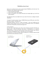
Quick Installation Guide
16-Channel Encoder
HR16
SAFETY
When installing your indoor HR16 encoder be sure to avoid:
o excessive heat, such as direct sunlight or heating appliances
o contaminants such as dust and smoke
o strong magnetic fields
o sources of powerful electromagnetic radiation such as radios or TV transmitters
o moisture and humidity
o areas with mechanical vibrations
o fluorescent lamps or objects that reflect light
o unstable light sources as this may cause flickering
o temperatures below -10° Celsius or 14° Fahrenheit and above 55° Celsius or 131°
Fahrenheit.
o For more details on installation and operation, please refer to the CD
provided.
POWER SUPPLY
HR16 Power consumption requirement: 12V DC, max 30W.
Ensure the supplied voltage meets the power consumption requirements of this encoder
before powering the encoder on. Incorrect voltage may cause irreparable damage to the
device and will effectively void the encoder warranty.
PoE power is not supported.
SERVICING
To avoid electrical shock and to preserve the product warranty, DO NOT disasemble the
encoder. Refer servicing to qualified personnel only.
PACKAGE CONTENTS
Ensure that the items received match those listed on the order form and the packing
slip. In addition to this manual and a fully assembled encoder, the encoder packing box
includes:
1. Rackmount brackets (2 pcs)
2. SATA flat cables (2 pcs)
3. HDD Power cable (1 pc)
4. Round-head screw, black (6 pcs). Use with the rackmount brackets.
5. Round-head screw, silver (8 pcs). Use to attach the HDD to the inside of the device.
6. 12V DC Power Supply
7. Power Cable
8. CAT5 Network cable. Connect HR16 to the Gigabit switch or directly to SRX-Pro Server.
9. Software CD with Annexxus Configuration Tool
i3-TRNG-CAMS-HR16-QIG.indd
Rev. 151118
1
9
2
3
4 5
6 7
8
10 11
12
13
14
15
16
IN
OUT
AUDIO
LAN
RS-485
12V
D+D-
POWER
VIDEO IN
1
2
4
3
5
6
7
8
2
9
No. Item Description
1 VIDEO IN 16 x BNC connectors for HDTVI & analog video input
2 USB Port Universal Serial Bus (USB) port for unit servicing
3 AUDIO IN Audio Input RCA connector
4 AUDIO OUT Audio Output RCA connector
5 LAN/Network Port CAT5 network connection port
6 RS-485 Interface RS-485 PTZ control connector
7 12V Power Input 12V DC Power Supply connector (inluded)
8 Power Switch Power switch for turning encoder ON/OFF
9 GND Ground
INSTALLATION
HR16 encoder is built in a 1U chassis for convenient rackmount installation.
Follow safety precautions when selecting installation location for your HR16 encoder.
1. Using supplied screws to secure the provided rack brackets to the HR16 unit, then
install your HR16 encoder into the server rack.
2. Make sure the Power Switch is in the OFF position.
3. Connect your HD-TVI or regular analog inputs to the 16 BNC connectors on the
encoder.
Note, that i3 HD-TVI cameras will have two coaxial cables: 720x480 (D1 quality)
and 1MP/2MP (720P/1080P quality). Make sure you connect the coaxial cable that
transmit your desired video quality.
4. Connect your video inputs’ PTZ signal cables (where applicable) to RS-485 block
on the rear panel of the encoder. Using a pointed object, press and hold the orange
toggle portion of the
D+ and D- RS-485
terminals and insert
the correct PTZ
signal cables into the
slots below. Release
the orange toggle to
secure the cables
in place. Ensure a
secure and tight
cable connection.
5. Connect your Audio IN and OUT devices, if using to the corresponding RCA
connectors on the rear panel.
6. Plug in the network cable into the LAN connector on the rear panel of the encoder
and then plug it into the Gigabit switch.
7. Connect the provided 12V power supply to the 12V DC Power Supply connector and
then plug in the supplied Power Cable into the provided power supply.
8. Plug the power cable into the power source. Use of the UPS (Uninterrupted Power
Supply) is highly recommended by i3 for added reliability and longevity of your
encoder.
9. Return the Power Switch into the ON position. The encoder will power on and the
front panel LEDs turn on.
1
9
2
3
4 5
6 7
8
10 11
12
13
14
15
16
IN
OUT
AUDIO
LAN
RS-485
12V
D+D-
POWER
VIDEO IN
RS-485
D+D-
Connect to the A+ of PTZ
Connect to the B- of PTZ
CONNECTING HR16 ENCODER TO i3 SRX-PRO SERVER
SRX-Pro Server is capable of supporting up to 2 (two) HR16 encoders.
Each encoder supports up to 16 analog or HD-TVI inputs, however, the number of inputs
that can be added to the SRX-Pro Server is determined by the number of purchased
licenses. When purchasing HR16 encoder, make sure to purchase enough “Analog
Channel” licenses to support all your HD-TVI and analog cameras.
When purchasing HR16 encoder(s) with the DVMS, connect your HR16 to the dedicated
NIC port(s) on your SRX-Pro Server through a provided CAT5 network cable.
When purchasing HR16 encoder(s) separately from the DVMS, connect your HR16 to an
i3-recommended Gigabit switch.
LAN
i3 SRX-Pro Server
Via Gigabit Switch
(optional)
i3 SRX-Pro Server
Connection Type 1 (when purchasing together with DVMS):
Connection Type 2 (when purchasing separately from DVMS):
(optional)
CAT5 connection
CAT5 connection

HR16, 16-Channel Video Encoder
QUICK INSTALLATION GUIDE
1. Close SRX-Pro Server software by pressing Alt+Shift+Ctrl+F4.
2. Change the IP address on the onboard NIC (LAN) (or on NIC1 if your
SRX-Pro Server has two onboard NIC cards) of your SRX-Pro Server to
192.0.0.XXX to match the default IP range of your HR16 encoder.
3. Make sure your HR16 encoder is connected to the same switch or is on
the same network as your i3 SRX-Pro Server (see diagrams).
4. Connect all your HD-TVI and analog inputs to HR16 encoder and turn on
your HR16 encoder
5. Launch the CD that came with your HR16 encoder and double-click
“setup.exe” file to install Annexxus Configuration Tool (ACT). ACT
application discovers all i3 cameras and encoders connected to your
network.
6. Follow the ACT installation instructions until the application has been
successfully installed on your SRX-Pro Server.
7. Double-click ACT icon on the Desktop to launch the application.
The application window will appear displaying a list of active network
cameras and encoders.
Next, select the desired HR16 encoder in the ACT software.
8. Enter the new IP address and Subnet Mask of the encoder in the Device
Communication area. The new encoder IP address must match the original
range of your SRX-Pro LAN or NIC1 card. E.g. If your original SRX-Pro
Server’s IP address was 192.168.1.122, change your HR16 encoder’s IP
address to 192.168.1.XXX.
Remember: HR16 encoders (if using more than one) cannot share an IP
address, each encoder requires its own unique IP address.
9. Make sure the Default account checkbox is checked and click Update.
10. Click Yes in the confirmation message window.
11. Wait a few minutes as the new IP address is being applied to your
HR16 encoder and the encoder restarts. Wait until the new IP address is
displayed next to your HR16 encoder in the ACT.
12. Repeat Steps 1-11 for all detected HR16 encoders in the Annexxus
Configuration Tool.
13. Make sure you can connect to the encoder through Internet Explorer:
a. Select the encoder in the list and click the corresponding IE icon.
b. Enter the default encoder User Name: i3admin and default Password:
i3admin.
c. Allow the add-on to be installed onto your computer. Follow
installation instructions.
d. HR16 encoder interface will be displayed in the Internet Explorer
window. You should be able to see the images of all connected
video inputs on the screen. If you do not see the video inputs on the
screen, call i3 International tech support for troubleshooting tips:
1.877.877.7241
14. Make sure that the latest version of GiPi updater is installed on your
SRX-Pro Server. The latest GiPi version is published on i3’s website:
http://i3international.com/index.php/software-downloads
15. Once the latest GiPi updater has been installed, restart i3 SRX-Pro Server.
16. Log In and go to the Setup -> IP Camera tab.
17. Click the Search button to display connected encoders and IP cameras.
18. Select the detected HR16 encoder in the list and click Select.
19. In the
Select IP Camera
window, enter the default HR16 encoder
User Name: i3admin and default Password: i3admin, then click Add.
20. The selected encoder with all connected analog inputs will be added to the
IP Camera list.
HR16 Encoder default IP: 192.0.0.16. Default Login / PW: i3admin / i3admin
ADDING HR16 INPUTS TO i3 SRX-PRO SERVER
21. Assign the video channel(s) in the IP Camera tab, to the SRX-Pro video
channel(s) in the Ch In. column (mandatory), as needed.
22. To control your PTZ inputs through SRX-Pro Server, select i3 GiPi in the PTZ
drop-down menu to the PTZ inputs.
23. Save the settings. Your HR16 encoder is now connected to SRX-Pro Server
and is ready to record. You may change resolution and frame rate for the
Main stream of each of the video inputs connected to HR16 in the IP Camera
tab menu.
ADJUSTING FRAME RATE AND RESOLUTION FOR INPUT
SUB-STREAMS.
Each analog video input connected to HR16 has two configurable streams:
Main Stream and Sub Stream. While some settings for the input’s Main Stream
(FPS and resolution) can be adjusted directly from SRX-Pro Server’s IP Camera
tab, the Sub Stream settings can only be adjusted through the HR16 browser
interface.
1. Go to Setup > IP Camera setup tab in SRX-Pro Server.
2. Select your HR16 encoder in the list and click the Advanced Setup button.
3. In the IE Browser window, enter HR16 login and password: i3admin /
i3admin.
4. Go to Setup > Camera > Video Settings.
5. In the Video Settings setup, select your Channel No. (video input number
that corresponds the BNC connector numbering on the HR16 rear panel).
6. Select Sub Stream in the Stream Type drop-menu.
7. Configure Sub Stream Resolution, Bitrate Type, Video Quality, Frame Rate,
and Max. Bit Rate values.
Note, that you are also able to adjust the same values for the camera’s
Main Stream from this menu, while only Frame Rate and Resolution can be
adjusted directly from the SRX-Pro setup.
8. When satisfied with the settings, click Save. Wait for Save succeeded
message.
9. You can also copy these settings to other connected analog inputs by
clicking on Copy to... (optional)
If you were able to add HR16 to IP Camera setup tab, but no video input
images can be viewed in SRX-Pro Server, make sure you have Analog
Channel licenses on your system. To check, go to Setup > System Info
> License Management. In the License Management window, check
the value in the Max Analog Channels line. If this value is set to 0,
contact Customer Care to purchase additional licensing.
CANADA 780 Birchmount Road,
Unit 16, Toronto,
ON, M1K 5H4
U.S.A 4450 Witmer Industrial Estates
Unit 4 Niagara Falls,
NY 14305
www.i3international.com
1.866.840.0004
/