®
SD-7098-SKDQ
Elbow RTE Push Plate
Manual
Features:
Oversized plate for increased visibility and
ease of use even when hands are not free
Low-profile design – only
7
/
8
" (22mm) thick
Dual-colored LED Indicates status
(red – standby, green – triggered)
Outputs rated 1A@30VDC, 0.5A@125VAC
Operating life: Over 100,000 cycles
(factory tested)
Operating voltage – 12/24VDC
2 Faceplates included
Momentary SPDT switch
Flexible mounting (surface, single-gang
back box, or European back box) allows for
quick and easy installation
Use with SECO-LARM maglocks for an
easily installed, high-security system

ENFORCER Elbow RTE Push Plate
2 SECO-LARM U.S.A., Inc.
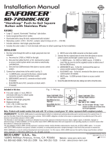
The ENFORCER Elbow RTE Push Plate is designed for easy, accessible entry and exit through
public area doors. The Elbow RTE Push Plate features a large button for easy, hands-free
operation, a red and green LED status indicator, and two stainless steel faceplates. With an
expected operating life of over 100,000 cycles and flexible mounting options, the ENFORCER
Elbow RTE Push Plate is the perfect solution for reliable, secure, and accessible entry and exit for
schools, hospitals, nursing homes, apartments, and other high-density public spaces.
1x Push Plate 2x Faceplates 1x Manual
Operating voltage 12/24VDC
Current draw
Standby 24mA@12VDC, 25mA@24VDC
Active 45mA@12VDC, 47mA@24VDC
Contact rating
Output 1 1A@30VDC, 0.5A@125VAC
Output 2 1A@30VDC, 0.5A@125VAC
Switch type Momentary NO/NC/COM (SPDT)
Contact resistance 50mΩ Max.(initial)
LED Status indicator Dual-colored LED (red – standby, green – triggered)
Operating life 100,000 Cycles (factory tested)
Material
Faceplate ABS Plastic with stainless steel insert
Switch box ABS Plastic
Dimensions 9
13
/
16
"x3
3
/
4
"x
7
/
8
" (250x95x22 mm)
Operating humidity 0~95% Non-condensing
Operating temperature 14°~113° F (-10°~45° C)
Weight 10.2-oz (289g)
Specifications:
Introduction:
Parts List:
9
13
/
16
"
(250mm)
7
/
8
"
(22mm)
Overview:
Switch Plate Removed
Switch Plate
Attachment
Notches
Wiring
Knockouts
3
3
/
4
"
(95mm)
LED
Status
Indicato
r
Side Front
Spring
Locator Pin
Terminal
Block
EXIT
SALIDA

ENFORCER Elbow RTE Push Plate
SECO-LARM U.S.A., Inc. 3
Installation:
Wiring Diagram:
Fig. 1 Fig. 2
Fig. 4
Circuit
board
Wiring
plugs
Fig. 6
Fig. 3
Spring
Fig. 5
Power (+)
Output #2 (N.C.)
Ground (—)
Output #1 (N.O.)
Output #1 (COM)
Output #1 (N.C.)
Output #2 (N.O.)
Output #2 (COM)
1. Determine a suitable location for the Push Plate.
2. Run wires through the wall to the desired location.
3. Insert a small screwdriver into the notches in the
switch plate (Fig. 1) and gently pry the switch plate
upwards until this edge pops free.
4. Slide the switch plate to the left until it is free of two
notches under the plate and lift it off (Fig. 2) taking
care not to lose the spring under it (Fig. 3).
5. Punch out the wiring plugs from the base (Fig. 4).
6. For mounting to a back box, use a small screwdriver
to remove the circuit board from the base to expose
the screw mount holes (Fig. 4, also "Overview,"
pg. 2). Additional holes are provided for direct
wall mounting.
7. Thread the wires through the wiring holes and
secure the base to the back box or wall. Replace the
circuit board if necessary and connect the wires to
the terminal block according to the wiring diagram
(see "Wiring Diagram" below).
8. Slide applicable faceplate, side with tabs first, fully
into the switch plate.
9. Place the spring over the spring locator pin on the
base (see "Overview," pg. 2) and use a small piece
of tape to hold it in place. Place the switch plate
over the base so that the tabs on the plate align with
the notches on the base and ensure that they are
properly engaged (Fig. 5). Press down on the right
side until it clicks into place (Fig 6).

ENFORCER Elbow RTE Push Plate
4 SECO-LARM U.S.A., Inc.
Also Available from SECO-LARM
®
:
Sample Application:
SECO-LARM
®
U.S.A., Inc.
16842 Millikan Avenue, Irvine, CA 92606 Website: www.seco-larm.com
Phone:
(
949
)
261-2999
|
(
800
)
662-0800 Email: sales
@
seco-larm.com
®
PITGW1
MI_SD-7098-SKDQ_180111.doc
x
NOTICE: The SECO-LARM policy is one of continual development and improvement. For that reason, SECO-LARM
reserves the right to change specifications without notice. SECO-LARM is also not responsible for misprints. All trademarks
are the property of SECO-LARM U.S.A., Inc. or their respective owners. Copyright © 2018 SECO-LARM U.S.A., Inc. All
rights reserved.
WARRANTY:
This SECO-LARM product is warranted against defects in material and workmanship while used in normal
service for one (1) year from the date of sale to the original customer. SECO-LARM’s obligation is limited to the repair or
replacement of any defective part if the unit is returned, transportation prepaid, to SECO-LARM. This Warranty is void if
damage is caused by or attributed to acts of God, physical or electrical misuse or abuse, neglect, repair or alteration,
improper or abnormal usage, or faulty installation, or if for any other reason SECO-LARM determines that such equipment
is not operating properly as a result of causes other than defects in material and workmanship. The sole obligation of
SECO-LARM and the purchaser’s exclusive remedy, shall be limited to the replacement or repair only, at SECO-LARM’s
option. In no event shall SECO-LARM be liable for any special, collateral, incidental, or consequential personal or property
damage of any kind to the purchaser or anyone else.
+
Power
Supply
+
+
_
+
_
Electromagnetic Lock
(E-941SA-1200 shown)
N.O. 2
N.C. 2
N.O. 1
N.C. 1
COM 1
COM 2
—
+
Electric Door Strikes Wireless RTE Plates RF Remote Control
SD-995C shown
SD-8202GT-PEQ
shown
SK- 910RBQ /
SK-919TP4J-NUQ
shown
/


