Date Issued: 09/15/17 IS-45926-US
Estamos aquí para ayudarle 866-558-5706
Horario: Lunes-Viernes 9am a 5pm EST (hora ocial del este)
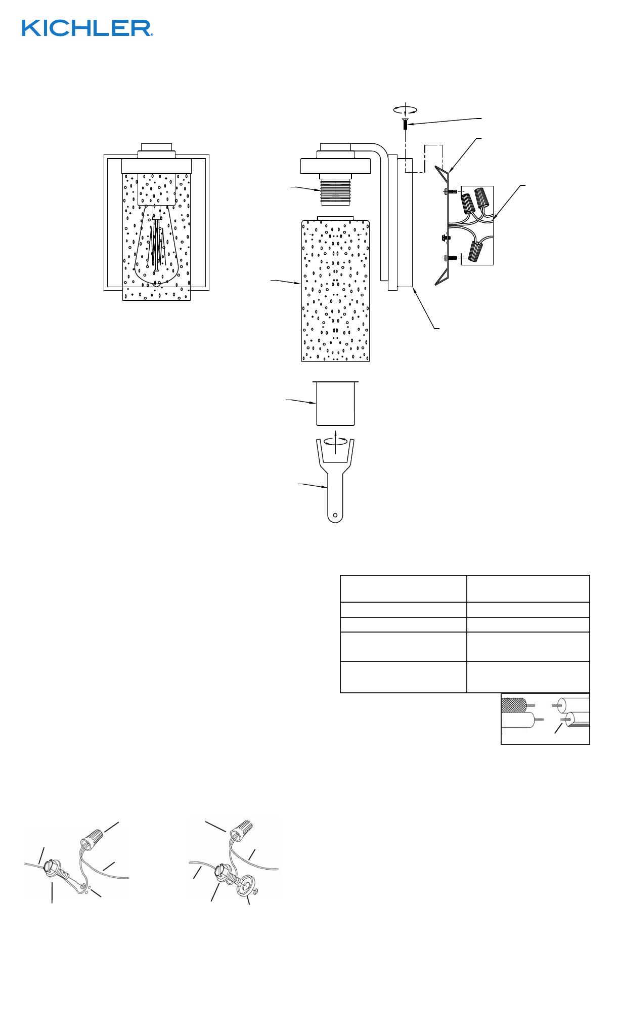
1) Unir la abrazadera de montaje[1] a la caja de conexiones[2].
La abrazadea de montge puede ajustarse para acomodar la
posición del artefacto.
2) Instrucciones para poner a tierra: (Ver Ilustraciones A o B).
A) En artefactos donde se suministra la abrazadera de
montaje con un agujero y dos depresiones onduladas.
Envuelva el conductor de tierra de la caja de salida
alrededor del tornillo de tierra verde y atornille en el
agujero.
B) En artefactos donde se suministra una arandela
cóncava. Fije el conductor de tierra de la caja de salida
debajo de la arandela cóncava y el tornillo de tierra
verde y enrosque en la abrazadera de montaje.
Si se suministra el artefacto con conductor de tierra. Conecte
el conductor de tierra del artefacto al conductor de tierra de
la caja de salida con conector de tierra después de seguir los
pasos anteriores. Nunca conecte el conductor de tierra a los
alambres de alimentación eléctrica negros o blancos.
ARANDELA
CONCAVA
TIERRA DE LA
CAJA DE SALIDA
TORNILLO DE TIERRA,
VERDE
DEPRESIONES
TIERRA
ARTEFACTO
CONECTOR DE ALAMBRE
TIERRA DE LA
CAJA DE SALIDA
TORNILLO DE TIERRA,
VERDE
TIERRA
ARTEFACTO
A
B
Conectar el alambre de
suministro negro o rojo al
Conectar el alambre de
suministro blanco al
Negro Blanco
*Cordon paralelo (redondo y liso)
*Cordon paralelo (cuadrado y estriado)
Claro, marrón, amarillio o negro
sin hebra identificadora
Claro, marrón, amarillio o negro
con hebra identificadora
Alambre aislado (diferente del verde)
con conductor de cobre
Alambre aislado (diferente del
verde) con conductor de plata
*Nota: Cuando se utiliza alambre paralelo
(SPT I y SPT II). El alambre neutro es de forma
cuadrada o estriada y el otro alambre será de
forma redonda o lisa. (Vea la ilustracíón).
Hilo Neutral
PRECAUCIÓN – RIESGO DE DESCARGA ELÉCTRICA –
Desconecte la electricidad en el panel principal del interruptor
automático o caja principal de fusibles antes de comenzar y
durante la instalación.
7
8
6
5
4
1
3
2
3) Haga las conexiones de los alambres. Re érase a la tabla de
abajo para realizar las conexiones correctas de los cables.
4) Empuje el artefacto a la pared, pasando cuidadosamente
los tornillos de montaje en los agujeros en el escudete[3][4].
Asegúrese de que todos los alambres estén dentro del escu-
dete y que no se pellizquen entre la pared y el escudete del
artefacto.
5) Enrosque las perillas de sujeción en los tornillos de montaje y
apriete para asegurar el artefacto a la pared.
6) Inserte la(s) bombilla(s) recomendadas (No se incluyen).
7) Levante el cristal [7] hasta la jación. Pase con cuidado el
enchufe [8] y alinee los oricios del soporte [9] con los oricios
del techo del aparato [10].
8) Enrosque un tornillo [11] en cada oricio desde la parte inferior
del techo del aparato. Apriete los tornillos para jar el vidrio en
su lugar.


