Page is loading ...

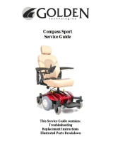
Compass Sport
™
Owner’s Manual
Compass Sport
™
Center-Wheel Drive Power Chair
GP605 SS/GP605 CC
YOUR LIFE IN MOTION
401 Bridge Street, Old Forge PA 18518
Tel: (800) 624-6374 Fax: (800) 628-5165
www.goldentech.com

Compass Sport Owner’s Manual – Model # GP605 SS, GP605 CC Revised 11/12/10
1

Compass Sport Owner’s Manual – Model # GP605 SS, GP605 CC Revised 11/12/10
2
FOR YOUR RECORDS
Please fill in your Compass Sport
™
information below. This information
will be useful in the event that you ever need to contact Golden Technolo-
gies, Inc. concerning your power chair.
Your Compass Sport
™
Model ____________________ Serial Number _________________
Date of Purchase ______________ Body Color ___________________
Options ________________
Your Golden Technologies, Inc. representative or dealer
Name ____________________________________
Company _________________________________
Address ________________________________________________________________
Please remember to fill in and return your warranty registration card.
ITEM CHECKLIST
Your Compass Sport
™ shipped with the items listed below.
Before assembly or disposal of the packaging material, please make certain
you have received all the items listed.
1. Main Frame
2. Seat assembly with arms.
3. Joystick
4. Lap Belt
5. Batteries (Two – U1) included.
6. (2) Battery cables

Compass Sport Owner’s Manual – Model # GP605 SS, GP605 CC Revised 11/12/10
3
CONTENTS
INTRODUCTION …………………………………………………… 4
SAFETY..............................................................………..
5-8
EMI/RFI ........................................................…….……..
9
SPECIFICATIONS……………………………………………………
10
ASSEMBLY/DISASSEMBLY………………………………………
11-16
COMFORT SETTINGS……………………………………………..
17-21
OPERATION/DIAGNOSTICS …………………………………….
22-27
BATTERY CHARGING …………………………………………….
28
CARE AND MAINTENANCE …………………………………….. 29
WARRANTY………………………………………………………….. 30-31
REGISTRATION CARD…………………………………………….
32

Compass Sport Owner’s Manual – Model # GP605 SS, GP605 CC Revised 11/12/10
4
INTRODUCTION
Congratulations on the purchase of your new Compass Sport
™
power chair. The Center-
wheel drive Compass Sport
™
combines cutting-edge technology with an attractive
design that is also highly functional in today’s world. We at Golden Technologies, Inc.
know that you have chosen a power chair that will give you years of dependable
operation and also will enhance the quality of your life by providing you with the
mobility to experience an active daily lifestyle.
Even though your new Compass Sport
™
is both user-friendly and designed for
maximum maneuverability in even the tightest spaces, we ask that you please read,
understand and follow all of the instructions and suggestions in this manual before
you operate your Compass Sports
™
for the first time. The safe use of your new power
chair is very important to us.
If you feel that you do not understand the instructions and suggestions presented in
this owner’s manual, or if, for any reason, you do not feel capable of performing the
activities necessary to assemble, disassemble, operate, or maintain your Compass
Sport
™
please contact your local Golden Technologies, Inc. representative or call
Golden Technologies, Inc. Technical Support Services at (800) 624-6374.
Golden Technologies, Inc. cannot be held responsible for personal injury or property
damage resulting from the unsafe or the improper use of any of our broad range of
health and personal mobility products. Our Research and Development Department,
our Quality Control Department, and our Engineering Department have used the latest
product specifications and the latest product design information to produce your
Compass Sport. Golden Technologies, Inc. reserves the right to implement changes into
our product lines when those changes become desirable or necessary. If changes are
implemented into our product line, there may be minor differences between the
product you purchased and the illustrations and instructions in this owner’s manual.
Please fill out and mail the enclosed warranty registration card on page 32. We at
Golden Technologies, Inc. would appreciate hearing about the dependability of your
Compass Sport
™
and about the convenience of mobility it has provided for you. We
would also appreciate hearing about the service you received from your local Golden
Technologies, Inc. representative.
Golden Technologies, Inc. Phone: (570) 451-7477
401 Bridge Street Fax: (570) 451-7494
Old Forge, PA 18518 Toll free:
(800) 624-6374
Web Site: www.goldentech.com

Compass Sport Owner’s Manual – Model # GP605 SS, GP605 CC Revised 11/12/10
5
SAFETY
Your Compass Sport
™
is a battery-operated personal mobility vehicle. Please exercise
caution and consideration when you are operating it. Driving your Compass Sport
™
carefully and thoughtfully will help ensure your personal safety and the safety of other
people.
NOTE: Before operating you Compass Sport, please ensure you read and
understand this owner’s manual in its entirety. If any uncertainty exist
after reading this manual, please ask for further instruction or training
from your authorized Golden Dealer / Representative.
BEFORE GETTING ON YOUR Compass Sport
™
Check to be certain that the power is turned off. See “Operation” on pages 21-26.
This will eliminate the possibility of accidentally activating the joystick and causing
injury to yourself or to others.
Check to be certain that your Compass Sport
™
is not in freewheel mode. See the
“Operation” section on page 26.
Flip up the armrests.
If your chair is equipped with leg rests, move them to the sides.
If your chair is equipped with a footrest, flip it to the “up” position.
GETTING ON YOUR Compass Sport
™
Carefully seat yourself comfortably and securely on the seat.
Adjust the leg rests or flip down the footrest.
Flip down the armrests.
Fasten the lap belt.
GETTING OFF YOUR Compass Sport
™
Make certain that the power is turned off.
Unfasten the lap belt.
Flip up the armrests.
Flip up the footrest, or move the leg rests to the sides.
Carefully stand and step away from the chair.
MAXIMUM WEIGHT
Your Compass Sport
™
has been rated to a maximum payload (passenger and anything
else being carried on the Compass Sport
™)
of 300 pounds. Exceeding the maximum
weight rating will void the warranty.
Exceeding the maximum weight capacity will void your warranty and may result
in injury to yourself or others.

Compass Sport Owner’s Manual – Model # GP605 SS, GP605 CC Revised 11/12/10
6
SAFETY
DRIVING ON AN INCLINE
Drive with caution when attempting to negotiate any incline, even handicap access
ramps.
Always climb or descend a gradient by driving straight up or straight down the face
of the slope.
Do not traverse or drive across the face of a gradient.
Do not attempt to negotiate an incline that is covered with snow, ice, cut or wet
grass, leaves, or any other potentially hazardous material.
Do not back down an incline.
Try to keep your Compass Sport
™
moving when climbing an incline. If you do come
to a stop, restart and accelerate slowly and carefully.
Do not try to descend or climb an incline that is greater than the maximum incline
stated in the specifications section of this manual.
If, while you are driving down a slope, your chair starts to move faster
than you feel is safe, gently release the joystick and allow your
Compass Sport
™
to come to a stop. When you feel that you again have
control of your power chair, adjust the speed control to a lower
setting, then push the joystick forward and continue safely down the
remainder of the slope.
MEDICATION
Always check with your physician to determine if any of the medications you are taking
may affect your judgment and/or your ability to operate your Compass Sport
™
.

Compass Sport Owner’s Manual – Model # GP605 SS, GP605 CC Revised 11/12/10
7
SAFETY
Do not attempt to use your Compass Sport
™
on an escalator. Always use an
elevator.
Do not carry passengers on your power chair.
Do not operate your Compass Sport
™
if it is not functioning properly.
Use caution when driving on soft or uneven surfaces such as grass, gravel, and on
decks where there is no railing.
Never drive on the roadway, except when you must cross the street.
Always cross streets at intersections and use the most direct route, making sure
that your path is clear and that you are visible to motor traffic.
Never drive your Compass Sport
™
up or down a step or curb that is higher than
1 1/2 inches.
Never back up or down a step or curb.
Never operate your Compass Sport
™
while you are under the influence of alcohol.
Do not operate or store your power chair where it will be exposed to rain, snow,
mist, and below freezing temperatures.
Do not operate your power chair on slippery, icy or salted surfaces.
Never sit on your power chair when it is in freewheel mode and on an incline or
decline.
Never place your power chair into freewheel mode without a trained assistant
present.
Do not sit on your power chair when it is freewheel mode without the presence of a
trained assistant.
Do not modify your power chair in any way that is not authorized by
Golden Technologies.
Do not disassemble the tire. If disassembly is required, have your authorized
Golden Compass Sport dealer perform any necessary maintenance or repair.
Do not attempt to inflate the tires of your Golden Compass Sport
™
. Your
Golden Compass Sport
™, is equipped with foam-filled flat free tires that do not
require inflation.

Compass Sport Owner’s Manual – Model # GP605 SS, GP605 CC Revised 11/12/10
8
SAFETY
Please be sure to follow this important warning when transferring onto or off of the
Golden Compass Sport power wheelchair:
NEVER TRANSFER ON OR OFF OF THIS POWER WHEELCHAIR USING THE SEAT
BACKREST FOR SUPPORT DURING TRANSFER. THE SEAT BACK MAY FOLD
DOWN AND MAY CAUSE YOU TO LOSE YOUR BALANCE AND COULD RESULT IN
PERSONAL INJURY.
DO NOT ALLOW ANYONE EXCEPT AN AUTHORIZED GOLDEN TECHNOLOGIES,
INC. REPRESENTATIVE TO CONNECT ANY ELECTRICAL OR MECHANICAL
DEVICE TO YOUR COMPASS SPORT™. UNAUTHORIZED ACCESSORIES WILL VOID
THE WARRANTY AND MAY CAUSE INJURY.

Compass Sport Owner’s Manual – Model # GP605 SS, GP605 CC Revised 11/12/10
9
EMI/RFI
The rapid development of electronics, especially in the area of communications, has
saturated our environment with electromagnetic (radio) waves that are emitted by
television transmitters, cellular phones, citizen’s band radios (CBs), amateur radios
(ham radios), wireless computer links, microwave transmitters, paging transmitters,
etc. These electromagnetic (EM) waves are invisible and increase in strength the closer
one gets to the source of transmission. When these energy waves act upon electrical
devices and cause them to malfunction or to function in an erratic or uncontrolled
manner, they are referred to as Electromagnetic Interference (EMI) or Radio Frequency
Interference (RFI).
EMI/RFI AND YOUR Compass Sport
™
All electrically powered vehicles, including power chairs are susceptible to EMI/RFI.
This interference could result in abnormal, unintended movement of a power
wheelchair.
The FDA has determined that each make and model of power chair can resist EMI/RFI
to a certain level. The higher the level of immunity, the greater the degree of protection
from EMI/RFI measured in volts per meter (V/m). The FDA has also determined that
current technology is capable of providing 20 V/m of immunity to EMI/RFI, which
would provide useful protection against common sources of interference.
Based on that determination, the FDA has written to the manufacturers of power
wheelchairs and asked them to test their new products to be certain that they provide a
reasonable degree of immunity to EMI/RFI. The FDA suggests that power chairs should
have an immunity level of 20 V/m.
The immunity level of the Compass Sport
™ is
20 V/m.
EMI/RFI RECOMMENDATIONS
Do not turn on or use hand-held personal electronic communication devices such as
cellular phones, walkie-talkies, and CB radios while your power chair is turned on.
Be aware of any nearby transmitters (radio, television, microwave, etc.) on your
intended route and avoid operating your chair close to any of those transmitters.
Turn off the power if your Compass Sport
™
is going to be in a stationary position for
any length of time.
Be aware that adding accessories or components or modifying your power chair may
make it more susceptible to EMI/RFI.
If unintended movement or brake release occurs, turn your power chair off as soon
as it is safe to do so.
Report all incidents of unintended movement or brake failure to your Golden repre-
sentative or to Golden Technologies, Inc. at (800) 624-6374.
Turn off your power chair as soon as it is safely possible if
unintended or uncontrollable motion occurs or if unintended brake
release occurs.

Compass Sport Owner’s Manual – Model # GP605 SS, GP605 CC Revised 11/12/10
10
SPECIFICATIONS
GP605 SS GP605 CC
Weight
Base 88 lbs 88 lbs
Seat Arms 12 lbs 12 lbs
Seat (18 X 18 Van Pan) 30 lbs
Seat (18 X 18 Captain's Highback) 32 lbs
Batteries (each) (2) required
. (weight varies by manufacturer)
U1 - 24 lbs U1 - 24 lbs
Total Weight with U1 Batteries 184 lbs 182 lbs
Dimensions
Length 39” 39"
Width (outside of tires) 25.4” 25.4”
Maximum Incline
6 degrees 6 degrees
Maximum Speed
4.1 mph 4.1 mph
Maximum Load Capacity
300 lbs 300 lbs
Turning Radius
21.5 " 21.5 "
Wheel Sizes
Drive Wheels (2) 10" X 3.5" 10" X 3.5"
Casters (4) 6" X 2" 6" X 2"
Maximum Seat Back Angle
115 degrees 115 degrees
Armrest Width (Adjustable)
Width of Seat
+6"
Width of Seat
+6"
Armrest Height (Adjustable)
.(Measured from seat cushion)
8", 9". & 10" 8", 9". & 10"
Seat Heights (Ground to Top of Seat)
Minimum Seat Height 21" 18"
Maximum Seat Height 23" 23"
Seat Back Heights (Ground to Top of Headrest)
Headrest Not Extended (Van Pan or Captain's Highback) 45.5"- 47.5” 45.5"- 47.5”
Headrest Extended (Van Pan or Captain's Highback) 49" - 51" 49" - 51
Without Headrest (Van Pan or Captain's Highback) 38.5" – 40.5" 38.5" – 40.5"
Footrest (Adjustable Height)
.(Measured from top of footrest to ground)
4", 4 3/4",
5 1/4", 5 3/4",
6 1/2"
4", 4 3/4",
5 1/4", 5 3/4",
6 1/2"
Footrest (Adjustable Angle)
-4 degrees to
17 degrees
-4 degrees to
17 degrees
Controller - Programmable
Dynamic
Shark
Dynamic
Shark
Charger - Off Board
Input
115/230 VAC
60/50 Hz,
3/1.5A
Output
24 VDC/3A
Input
115/230 VAC
60/50 Hz,
3/1.5A
Output
24 VDC/3A
Battery Types (recommended)
(2) U1 (2) U1
Shroud Colors (all models)
Red and Blue
Note: Golden Technologies reserves the right to alter or change any specification without prior notice.

Compass Sport Owner’s Manual – Model # GP605 SS, GP605 CC Revised 11/12/10
11
ASSEMBLY/DISASSEMBLY
Your Compass Sport
™
is shipped partially disassembled in order to maximize the
protection of all its parts during the shipping process. Please follow the instruction
below to quickly and easily assemble the power chair for your use.
NOTE: You will need only basic tools. If you do not have the required tools, or if
you do not feel capable of safely assembling your power chair, please contact
your local Golden Technologies, Inc. representative.
Main Components
1. Frame with power module, controller cable & connectors for battery cables
2. Battery box covers
3. Seat assembly
4. Joystick
5. Batteries (Two – U1)
6. Seat Belt
Front Battery Box
Cover
Seat Assembly
Joystick
Seat Belt
Rear Battery Box
Cover
Center Wheel Fenders
Caster Arm Cover
Joystick Batteries

Compass Sport Owner’s Manual – Model # GP605 SS, GP605 CC Revised 11/12/10
12
ASSEMBLY / DISASSEMBLY
SEAT INSTALLATION/REMOVAL
Note: The seat assembly weighs about 46 pounds. Please ask for help if you do
not feel capable of safely lifting that much weight. Removal of arms will
significantly reduce the weight of seat.
INSTALLATION
1. To install the seat, align the seat post stinger on the bottom of the seat with
the hole in the seat post receiver on the chair. See figures 3 and 4 on page 13.
2. Lift the seat lock lever and while holding the lever rotate the seat until it
aligns and seats into place. See figure 2 on page 13.
3. Attach arms by loosening the arm width adjustment knobs (See figure 16 on
Page 21). Insert left arm into left receiving tube and tighten the arm width
adjustment knob. Repeat with right arm.
4. Attach joystick to right arm. (See Joystick Installation/Removal on page 14.)
5. Connect the controller cable to the joystick and use the Velcro tie-wraps to
secure the cable to the armrest bracket.
6. Lift the Backrest Angle Adjustment Lever (See Figure 1 on page 13) and while
holding the lever, lift the seat back to an upright angle.
REMOVAL
1. Disconnect the controller cable from the joystick. See figure 6 on page 14.
Remove Velcro tie-wraps from the controller cable.
2. Remove arms by loosening the arm width adjustment knobs and pulling arms
out of the receiving tubes.
3. With one hand brace the seat back. With the other hand lift the Backrest
Angle Adjustment Lever and while holding the lever, lower the back of the seat
to the seat.
Lifting the Backrest Angle Adjustment Lever will cause the back to
automatically close towards the seat. Improper handling may
result in injury.
4. Lift the seat lock handle and while holding the lever rotate the seat and lift the
seat off the seat post receiver. See figure 2 on page 13.
BE SURE THE SEAT IS CORRECTLY INSTALLED AND
LOCKED BEFORE OPERATING YOUR POWER CHAIR.

Compass Sport Owner’s Manual – Model # GP605 SS, GP605 CC Revised 11/12/10
13
ASSEMBLY / DISASSEMBLY
Front Seat Lock
Handle
Backrest Angle
Adjustment Lever
Figure 1 Figure 2
Seat Post Receiver
Seat Post
Stinger
Figure 3 Figure 4
Battery Box
Covers

Compass Sport Owner’s Manual – Model # GP605 SS, GP605 CC Revised 11/12/10
14
ASSEMBLY / DISASSEMBLY
JOYSTICK INSTALLATION
1. Position the joystick on the joystick bracket. Match the holes in the joystick with the
holes in the bracket. See figure 5.
2. Insert the 4 Allen-head screws with lock washers through the bracket and into the
holes in the joystick.
3. Use an Allen wrench to tighten the screws.
4. Connect the joystick cable to the controller cable. See figure 6.
5. Use the provided Velcro tie-wraps and under arm clip to secure the controller
cable to the armrest bracket.
6. To disassemble, turn off joystick controller and then reverse the process above.
Allen-head screws
Jo
y
stick Bracket
Figure 5
Jo
y
stick Cable
Figure 6

Compass Sport Owner’s Manual – Model # GP605 SS, GP605 CC Revised 11/12/10
15
ASSEMBLY / DISASSEMBLY
Accessing the batteries
After removing the seat, locate the (2) “Battery
Box Covers”, on front and rear. Remove one of the
covers by lifting up on the outer edge of the cover.
Remove the second “Battery Box
Cover” by lifting up on the outer
edge of the cover.
Note: On the inside of the battery
box cover there is a battery
connection dia
g
ram.

Compass Sport Owner’s Manual – Model # GP605 SS, GP605 CC Revised 11/12/10
16
ASSEMBLY/ DISASSEMBLY
BATTERY INSTALLATION
Note: The batteries weigh 24 pounds each. (Battery weights may vary depending
on the manufacturer). Please ask for help if you do not feel capable of safely
lifting that much weight.
Battery shown with cable
connected properly.
Figure 7 Figure 8
Buckle Strap
Batter
y
Terminal
Figure 9
1. Use the screws, washers, and nuts provided to connect the positive (red booted)
connector of each cable to the positive (+) terminal of each battery. See figure 7and
figure 8.
2. Use the screws, washers, and nuts provided to connect the negative (black booted)
connector of each cable to the negative (-) terminal of each battery.
2. Place the batteries in the battery box. Be certain to position the terminals on each
battery away from the seat post on the unit as shown in Figure 9. Secure the
batteries in place using the buckle straps.
3. Connect the connectors of each battery cable to the corresponding connector on the
main wire harness. See figure 9
4. Cover the battery terminals with the protective caps provided. See figure 9.
5. Install both Battery Box Covers.
6. T
o disassemble, please reverse the above process.

Compass Sport Owner’s Manual – Model # GP605 SS, GP605 CC Revised 11/12/10
17
COMFORT SETTINGS
You may be spending a great deal of time on your Compass Sport
™
. To provide you with
the maximum seating comfort, Golden Technologies, Inc. has designed this power chair
to incorporate the following adjustments for operator comfort.
COMFORT SETTINGS
1. Seat height 4. Footrest angle
2. Headrest height 5. Footrest height
3. Backrest angle 6. Joystick bracket length
Make certain that the power to your Compass Sport
™
is
turned off before making any adjustments, to eliminate the risk of the
joystick being accidentally bumped and activating the power chair.
If you do not feel capable of safely making these adjustments, please contact your local
Golden representative.
Seat height adjustment
The seat post is a design that is adjustable in height. Adjustment is made by removing
the seat post bolt, raising or lowering the seat post to the desired height and re-
installing the seat post bolt.
Seat Post Receiver
Seat Post Bolt
(5/16” Allen)
Nut (17mm)

Compass Sport Owner’s Manual – Model # GP605 SS, GP605 CC Revised 11/12/10
18
COMFORT SETTINGS
HEADREST HEIGHT ADJUSTMENT
1. Standing behind the chair, push and then release the clamp on the left post of the
headrest while you are pulling up or pushing down on the head rest. See figure 10.
2. The headrest will “click” to a stop in one of the preset positions.
3. Repeat step 1 until the headrest is at the desired height.
Headrest Clamp
Backrest Angle
Ad
j
ustment Leve
r
Figure 10 Figure 11
BACKREST ANGLE ADJUSTMENT
NOTE: The backrest can be folded down to minimize chair
height during transport.
1. Pull up on the adjustment lever (see figure 11) and push against the backrest until
the backrest is in the desired position.
2. Release the lever.
3. To return the backrest to the upright position, pull up on the lever and move the
backrest to the desired position.

Compass Sport Owner’s Manual – Model # GP605 SS, GP605 CC Revised 11/12/10
19
COMFORT SETTINGS
FOOTREST ANGLE ADJUSTMENT
1. Fold the footrest upward for easy access to the
angle adjustment bolt. See figure 12
2. Turn the jam nut counter-clockwise with a 17mm
wrench to loosen.
3. Use a 5/16” Allen wrench to turn the adjustment
bolt. Turn the adjustment bolt counter-clockwise
to increase the footrest angle. Turn the
adjustment bolt clockwise to decrease the footrest
angle.
4. When the desired footrest angle is reached, re-
tighten the jam nut.
Jam Nut (17mm)
Footrest Angle Adjustment
Bol
t
(
5/16” Allen
)
Figure 12
FOOTREST HEIGHT ADJUSTMENT
1. Remove front cover.
2. Use a 13mm socket and 5mm Allen wrench to remove the bolts indicated in
figure 13.
3. Slide the footrest to the desired height.
4. Align the bolt holes in the footrest and the footrest bracket.
5. Install and tighten the bolts.
Footrest Height
Adjustment Bolts
(
5mm Allen
)
N
uts
(
13mm
)
Figure 13
/