Supermicro 4020A-8R User manual
- Category
- Server barebones
- Type
- User manual
This manual is also suitable for

A+ SERVER 4020A-8R
USER’S MANUAL
1.0

The information in this User’s Manual has been carefully reviewed and is believed to be accurate.
The vendor assumes no responsibility for any inaccuracies that may be contained in this document,
makes no commitment to update or to keep current the information in this manual, or to notify any
person or organization of the updates.
Please Note: For the most up-to-date version of
this manual, please see our web site.
The Manufacturer reserves the right to make changes to the product described in this manual at
any time and without notice. This product, including software, if any, and documentation may not,
in whole or in part, be copied, photocopied, reproduced, translated or reduced to any medium or
machine without prior written consent.
IN NO EVENT WILL WE BE LIABLE FOR DIRECT, INDIRECT, SPECIAL, INCIDENTAL,
SPECULATIVE OR CONSEQUENTIAL DAMAGES ARISING FROM THE USE OR INABILITY TO
USE THIS PRODUCT OR DOCUMENTATION, EVEN IF ADVISED OF THE POSSIBILITY OF
SUCH DAMAGES. IN PARTICULAR, THE VENDOR SHALL NOT HAVE LIABILITY FOR ANY
HARDWARE, SOFTWARE, OR DATA STORED OR USED WITH THE PRODUCT, INCLUDING
THE COSTS OF REPAIRING, REPLACING, INTEGRATING, INSTALLING OR RECOVERING
SUCH HARDWARE, SOFTWARE, OR DATA.
Any disputes arising between manufacturer and customer shall be governed by the laws of Santa
Clara County in the State of California, USA. The State of California, County of Santa Clara shall
be the exclusive venue for the resolution of any such disputes. The manufacturer's total liability for
all claims will not exceed the price paid for the hardware product.
Unless you request and receive written permission from the Manufacturer, you may not copy any
part of this document.
Information in this document is subject to change without notice. Other products and companies
referred to herein are trademarks or registered trademarks of their respective companies or mark
holders.
Copyright © 2005
All rights reserved.
Printed in the United States of America

Preface
About This Manual
This manual is written for professional system integrators and PC technicians. It
provides information for the installation and use of the A+ Server 4020A-8R. Instal-
lation and maintainance should be performed by experienced technicians only.
The 4020A-8R is a high-end 2U rackmount server based on the SC743S1-R760
4U/rackmount server chassis and the H8DA8 serverboard, which supports single
or dual AMD Opteron™ 200 series processors and up to 32 GB of ECC registered
DDR266 or 16 GB of ECC registered DDR400/333 SDRAM memory.
Manual Organization
Chapter 1: Introduction
The fi rst chapter provides a checklist of the main components included with the
server system and describes the main features of the H8DA8 serverboard and the
SC743S1-R760 chassis, which make up the 4020A-8R.
Chapter 2: Server Installation
This chapter describes the steps necessary to install the 4020A-8R into a rack and
check out the server confi guration prior to powering up the system. If your server
was ordered without processor and memory components, this chapter will refer you
to the appropriate sections of the manual for their installation.
Chapter 3: System Interface
Refer here for details on the system interface, which includes the functions and
information provided by the control panel on the chassis as well as other LEDs
located throughout the system.
iii
Preface

A+ Server 4020A-8R User's Manual
iv
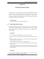
Chapter 4: System Safety
You should thoroughly familiarize yourself with this chapter for a general overview
of safety precautions that should be followed when installing and servicing the
4020A-8R.
Chapter 5: Advanced Serverboard Setup
Chapter 5 provides detailed information on the H8DA8 serverboard, including the
locations and functions of connectors, headers and jumpers. Refer to this chapter
when adding or removing processors or main memory and when reconfi guring the
serverboard.
Chapter 6: Advanced Chassis Setup
Refer to Chapter 6 for detailed information on the SC743S1-R760 4U rackmount
server chassis. You should follow the procedures given in this chapter when install-
ing, removing or reconfi guring SCSI or peripheral drives and when replacing the
system power supply unit and cooling fans.
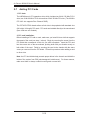
Chapter 7: BIOS
The BIOS chapter includes an introduction to BIOS and provides detailed informa-
tion on running the CMOS Setup Utility.
Appendix A: BIOS Error Beep Codes
Appendix B: BIOS POST Codes
Appendix C: System Specifi cations

v
Preface
Notes

A+ Server 4020A-8R User's Manual
vi
Table of Contents
Preface
About This Manual ...................................................................................................... iii
Manual Organization ................................................................................................... iii
Chapter 1: Introduction
1-1 Overview ......................................................................................................... 1-1
1-2 Serverboard Features ..................................................................................... 1-2
1-3 Server Chassis Features ................................................................................ 1-4
Chapter 2: Server Installation
2-1 Overview ......................................................................................................... 2-1
2-2 Unpacking the System ................................................................................... 2-1
2-3 Preparing for Setup ........................................................................................ 2-1
Choosing a Setup Location .................................................................... 2-2
Rack Precautions .................................................................................... 2-2
Server Precautions ................................................................................. 2-2
Rack Mounting Considerations ............................................................... 2-3
2-4 Installing the System into a Rack ................................................................... 2-3
Identifying the Sections of the Rails ....................................................... 2-3
Installing the Chassis Rails ...................................................................... 2-5
Installing the Rack Rails .......................................................................... 2-6
Installing the Server into the Rack ........................................................... 2-7
Installing the Server into a Telco Rack .................................................... 2-7
2-5 Checking the Serverboard Setup ................................................................... 2-8
2-6 Checking the Drive Bay Setup ....................................................................... 2-8
Chapter 3: System Interface
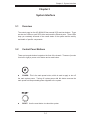
3-1 Overview ......................................................................................................... 3-1
3-2 Control Panel Buttons .................................................................................... 3-1
Reset ....................................................................................................... 3-1
Power ...................................................................................................... 3-1
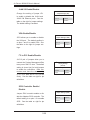
3-3 Control Panel LEDs ........................................................................................ 3-2
Power ..................................................................................................... 3-2
HDD .......................................................................................................... 3-2
NIC1 ......................................................................................................... 3-2
NIC2 ......................................................................................................... 3-2
Overheat/Fan Fail .................................................................................... 3-2

Power Fail ................................................................................................ 3-3
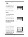
3-4 SCSI Drive LEDs ............................................................................................ 3-3
3-5 LAN (Ethernet) Port LEDs .............................................................................. 3-3
Chapter 4: System Safety
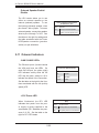
4-1 Electrical Safety Precautions .......................................................................... 4-1
4-2 General Safety Precautions ........................................................................... 4-2
4-3 ESD Precautions ............................................................................................ 4-3
4-4 Operating Precautions .................................................................................... 4-4
4-5 Disposing of Electronic Equipment ................................................................ 4-4
Chapter 5: Advanced Serverboard Setup
5-1 Handling the Serverboard .............................................................................. 5-1
5-2 Mounting the Serverboard into a Chassis ...................................................... 5-2
5-3 Processor and Heatsink Installation ............................................................... 5-2
5-4 Connecting Cables ......................................................................................... 5-4
Connecting Data Cables .......................................................................... 5-5
Connecting Power Cables ....................................................................... 5-5
Connecting the Control Panel .................................................................. 5-6
5-5 I/O Ports ......................................................................................................... 5-7
5-6 Installing Memory ........................................................................................... 5-7
5-7 Adding PCI Cards ......................................................................................... 5-10
5-8 Serverboard Details ...................................................................................... 5-10
H8DA8 Serverboard Layout .................................................................. 5-11
H8DA8 Quick Reference ........................................................................ 5-12
5-9 Connector Defi nitions ................................................................................... 5-13
ATX Power Connection .......................................................................... 5-13
Secondary Power Connector ................................................................. 5-13
NMI Button ............................................................................................. 5-13
Power LED ............................................................................................. 5-13
HDD LED ............................................................................................... 5-14
NIC1 LED ............................................................................................... 5-14
NIC2 LED ............................................................................................... 5-14
Overheat/Fan Fail LED .......................................................................... 5-14
Power Fail LED ...................................................................................... 5-14
Reset Button .......................................................................................... 5-15
Power Button .......................................................................................... 5-15
Universal Serial Bus ............................................................................... 5-15
Chassis Intrusion .................................................................................... 5-15
Serial Ports ............................................................................................. 5-16
vii
Table of Contents

A+ Server 4020A-8R User's Manual
viii
Power Fail and Alarm Reset Header ..................................................... 5-16
Fan Headers .......................................................................................... 5-16
JLAN 1/2 (Ethernet Ports) ....................................................................... 5-16
Extra USB Headers ................................................................................ 5-17
Power LED/Speaker ............................................................................... 5-17
ATX PS/2 Keyboard & Mouse Ports ...................................................... 5-17
Wake-On-LAN ........................................................................................ 5-18
Wake-On-Ring ........................................................................................ 5-18
SMB Power ............................................................................................ 5-18
SMB Header ........................................................................................... 5-18
5-10 Jumper Settings ............................................................................................ 5-19
Explanation of Jumpers ......................................................................... 5-19
CMOS Clear ........................................................................................... 5-19
JLAN Enable/Disable ............................................................................. 5-20
VGA Enable/Disable ............................................................................... 5-20
I
2
C to PCI Enable/Disable ...................................................................... 5-20
SCSI Controller Enable/Disable ............................................................. 5-20
SCSI Termination Enable/Disable .......................................................... 5-21
3rd Power Supply Fail Signal Enable/Disable ....................................... 5-21
Watch Dog Enable/Disable .................................................................... 5-21
Onboard Speaker Enable/Disable ......................................................... 5-22
5-11 Onboard Indicators ....................................................................................... 5-22
JLAN1/JLAN2 LEDs ............................................................................... 5-22
+3.3V Power LED .................................................................................. 5-22
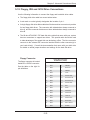
5-12 Floppy, IDE and SCSI Drive Connections .................................................... 5-23
Floppy Connector ................................................................................... 5-23
IDE Connectors ...................................................................................... 5-24
SCSI Connectors ................................................................................... 5-25
Chapter 6: Advanced Chassis Setup
6-1 Static-Sensitive Devices ................................................................................. 6-1
6-2 Front Control Panel ........................................................................................ 6-3
6-3 System Fans ................................................................................................... 6-4
Fan Failure ............................................................................................... 6-4
Replacing Chassis Cooling Fans ............................................................. 6-4
6-4 Drive Bay Installation ...................................................................................... 6-6
SCSI Drives .............................................................................................. 6-6
Installing Components in the 5.25" Drive Bays ....................................... 6-9
6-5 Power Supply ............................................................................................... 6-10

Table of Contents
ix
Power Supply Failure ............................................................................. 6-10
Replacing the Power Supply .................................................................. 6-10
Chapter 7: BIOS
7-1 Introduction ..................................................................................................... 7-1
7-2 Main Setup ..................................................................................................... 7-2
7-3 Advanced Setting Menu ................................................................................. 7-2
7-4 PCI/PnP Menu .............................................................................................. 7-10
7-5 Boot Menu .................................................................................................... 7-11
7-6 Security Menu ............................................................................................... 7-13
7-7 Chipset Menu ............................................................................................... 7-14
7-8 Power Menu ................................................................................................. 7-18
7-9 Exit Menu ...................................................................................................... 7-19
Appendices:
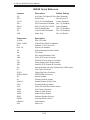
Appendix A: BIOS Error Beep Codes ..................................................................... A-1
Appendix B: BIOS POST Codes ............................................................................ B-1
Appendix C: System Specifi cations ........................................................................ C-1

A+ Server 4020A-8R User's Manual
x
Notes

Chapter 1: Introduction
1-1
Chapter 1
Introduction
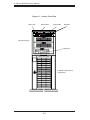
1-1 Overview
The 4020A-8R is a high-end dual processor server featuring some of the most
advanced technology currently available. The 4020A-8R is comprised of two main
subsystems: the SC743S1-R760 tower/4U rackmount chassis and the H8DA8 dual
processor serverboard. Please refer to our web site for information on operating
systems that have been certifi ed for use with the 4020A-8R.
In addition to the mainboard and chassis, various hardware components may have
been included with your 4020A-8R, as listed below:
One (1) 3.5" fl oppy drive [FPD-PNSC-02 (white) or FPD-PNSC-01 (black)]
Two (2) passive heatsinks for 2U server, optional (SNK-P0013)
Four (4) 8-cm hot-swap chassis fans (FAN-0072)
Two (2) 8-cm hot-swap exhaust fans (FAN-0073)
One (1) air shroud for 1U chassis (CSE-PT54)
Two (2) CPU backplates (BKT-0004)
Two (2) heatsink retention modules with four (4) screws (BKT-0005)
SCSI Accessories:
One (1) SCA SAF-TE compliant single-channel SCSI backplane (CSE-SCA-
743S1)
One (1) 9" two-drop Ultra320 SCSI cable (CBL-037-U320)
Eight (8) SCA 1-inch high SCSI drive carriers [CSE-PT17(B)]
Rail kit, optional [CSE-PT26(B)]
One (1) CD containing drivers and utilities
One (1) 4020A-8R User's Manual
Note: a "B" at the end of a part number indicates the item is available in black.

A+ Server 4020A-8R User's Manual
1-2
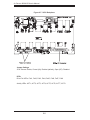
1-2 Serverboard Features
At the heart of the 4020A-8R lies the H8DA8 a dual processor serverboard de-
signed to provide maximum performance. Below are the main features of the
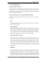
H8DA8. See Figure 1-1 for a system block diagram of the chipset.
Processors
The H8DA8 supports single or dual 940-pin AMD Opteron
TM
processors. Please
refer to our web site for a complete listing of supported processors.
Memory
The H8DA8 has eight 184-pin DIMM slots that can support up to 32 GB of reg-
istered ECC DDR266 or up to 16 GB of registered ECC DDR400/333 SDRAM.
(The maximum memory supported is halved if only one processor is installed.)
Memory in supported in both interleaved and non-interleaved confi gurations. See
Section 5-6 for details.
Onboard SCSI
Onboard SCSI is provided with Adaptec's AIC-7902 SCSI controller chip, which
supports dual-channel, Ultra320 SCSI at at maximum throughput of 320 MB/sec
for each channel. The H8DA8 provides two LVD Ultra320 SCSI ports. The SCSI
drives are hot-swappable units.
Note: The operating system you use must have RAID support to enable the hot-
swap capability and RAID function of the SCSI drives.
PCI Expansion Slots
The H8DA8 has six PCI expansion slots, which includes two 64-bit 133 MHz PCI-X
slots, two 64-bit 66 MHz PCI-X slots and two 32-bit 33 MHz PCI slots. (The 66 MHz
PCI-X #3 slot supports Zero Channel RAID.)

Chapter 1: Introduction
1-3
ATI Graphics Controller
An ATI video controller based on the Rage XL 8 MB graphics chip is integrated
onboard the H8DA8. Rage XL fully supports sideband addressing and AGP
texturing. This onboard graphics package can provide a bandwidth of up to 512
MB/sec over a 32-bit graphics memory bus.
Onboard Controllers/Ports
The H8DA8 provides one fl oppy drive controller and two onboard IDE control-
lers, which support up to four hard drives or ATAPI devices. Backpanel I/O ports
include one COM port, two USB ports, PS/2 mouse and keyboard ports and a
video (monitor) port. A Broadcom BCM5704 Ethernet controller is also included
to support two Gb LAN ports.
Other Features
Other onboard features are included to promote system health. These include
various voltage monitors, CPU temperature sensors, fan speed sensors, a chas-
sis intrusion header, auto-switching voltage regulators, chassis and CPU overheat
sensors, virus protection and BIOS rescue.

A+ Server 4020A-8R User's Manual
1-4
1-3 Server Chassis Features
The SC743S1-R760 is a scaleable server platform that may be deployed either
in a tower or a 4U rackmount confi guration. The following is a general outline of
the main features of the SC743S1-R760 chassis.
System Power
The SC743S1-R760 features a triple redundant 760W power supply that consists
of three separate power supply modules. These modules all share the load and run
continuously. If any of the three fail, the remaining two pick up the load and keep
the system running without interruption. A failed power supply module will illuminate
the power fail LED. The power supply modules are all hot-swappable, so you don’t
have to power down the system to replace a module.
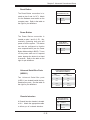
SCSI Subsystem
The SCSI subsystem supports eight 80-pin SCA Ultra320 SCSI hard drives. (Any
standard 1" drives are supported. SCA = Single Connection Attachment.) The SCSI
drives are connected to an SCA backplane that provides power, bus termination and
confi guration settings. The SCSI drives are also hot-swap units
Note: The operating system you use must have RAID support to enable the hot-
swap capability of the SCSI drives.
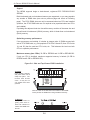
Control Panel
The chassis' control panel provides you with system monitoring and control. LEDs
indicate system power, HDD activity, network activity, system overheat/fan fail and
power supply failure. A main power button and a system reset button are also
included..
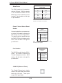
I/O Backplane
The SC743S1-R760 is an Extended ATX form factor chassis that can be used either
as a tower or as a 4U rackopunrt unit. The I/O backplane provides six motherboard
expansion slots, one COM port, a VGA port, two USB ports, PS/2 mouse and key-
board ports, a parallel port and two gigabit Ethernet ports.

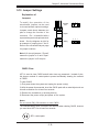
Chapter 1: Introduction
1-5
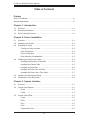
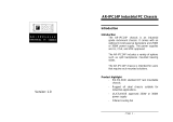
Figure 1-1. AMD 8131/8111
TM
Chipset:
System Block Diagram
Note: This is a general block diagram. See Chapter 5 for details.
Cooling System
The The SC743S1-R760 chassis has an innovative cooling design that includes
four 8-cm hot-plug system cooling fans located in the middle section of the chas-
sis and two 8-cm hot-plug rear exhaust fans. Each power supply module also
includes a cooling fan. An air shroud, which directs the airfl ow to the areas of
highest heat build-up, is also included. All chassis and power supply fans operate
continuously.
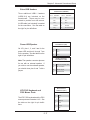
A setting in BIOS (see p. 7-18) is used to control the system fan speed. This setting
uses voltage control to allow fans to run at different speeds. [The recommended
setting is “4-pin (Server)”.]
AMD-8111
AMD-8131
AMD
Opteron
TM
Processor (1)
AMD
Opteron
TM
Processor (2)
184-pin DIMMs184-pin DIMMs 16 x 16 Hyper Tr ansport (2000 MT/s)
16 x 16 Hyper Transpor t (1200 M T/s)
144 -bit, 200 - 400 M T/s
144 -bit, 200 -400 MT/s
133 / 100 MHz PCI-X Slots
Adaptec
AIC-7902W
Broadcom
BC5704C
100 /66 MH z PCI- X Sl ots
ATA133
USB 1.1
33 MHz PC I Slots
ATI
Rage XL
8 MB
Winbond
W83627HF
Super I /O
PS/2 Kybd/Mouse
Floppy Disk Drive
Serial Ports
Parallel Port
BIOSLPC Link
8 x 8 ncHyper Tr ansport (400 MT/s)

A+ Server 4020A-8R User's Manual
1-6
Notes

Chapter 2: Server Installation
2-1
Chapter 2
Server Installation
2-1 Overview
This chapter provides a quick setup checklist to get your AS 4020A-8R server up
and running. Following these steps in the order given should enable you to have
the system operational within a minimum amount of time. This quick setup assumes
that your system has come to you with the processors and memory preinstalled. If
your system is not already fully integrated with a serverboard, processors, system
memory etc., please turn to the chapter or section noted in each step for details
on installing specifi c components.
The AS 4020A-8R may be employed either as a tower or mounted in a rack as a
4U rackmount chassis. If using it as a tower unit, please read the Server Precau-
tions in the next section and then skip ahead to Section 2-5.
2-2 Unpacking the System
You should inspect the box the system was shipped in and note if it was damaged
in any way. If the server itself shows damage you should fi le a damage claim with
the carrier who delivered it.
Decide on a suitable location for the AS 4020A-8R. It should be situated in a clean,
dust-free area that is well ventilated. Avoid areas where heat, electrical noise and
electromagnetic fi elds are generated. You will also need it placed near a grounded
power outlet. Be sure to read the Rack and Server Precautions in the next sec-
tion.
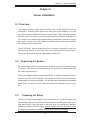
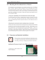
2-3 Preparing for Setup
The box the system was shipped in may include two sets of rail assemblies, two
rail mounting brackets and mounting screws needed for installing the system into a
rack (optional kit). Follow the steps in the order given to complete the installation
process in a minimum amount of time. Please read this section in its entirety before
you begin the installation procedure outlined in the sections that follow.

2-2
A+ Server 4020A-8R User's Manual
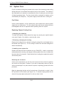
Choosing a Setup Location
- Leave enough clearance in front of the system to enable you to open the front
door completely (~25 inches).
- Leave approximately 30 inches of clearance in the back of the system to allow for
suffi cient airfl ow and ease in servicing.
- This product is for installation in a Restricted Access Location only (dedicated
equipment rooms, service closets, etc.)
Rack Precautions
- Ensure that the leveling jacks on the bottom of the rack are fully extended to the
fl oor with the full weight of the rack resting on them.
- In single rack installation, stabilizers should be attached to the rack.
- In multiple rack installations, the racks should be coupled together.
- Always make sure the rack is stable before extending a component from the
rack.
- You should extend only one component at a time - extending two or more simul-
taneously may cause the rack to become unstable.
Server Precautions
- Review the electrical and general safety precautions in Chapter 4.
- Determine the placement of each component in the rack before you install the
rails.
- Install the heaviest server components on the bottom of the rack fi rst, and then
work up.
- Use a regulating uninterruptible power supply (UPS) to protect the server from
power surges, voltage spikes and to keep your system operating in case of a power
failure.
- Allow the hot plug SCSI drives and power supply units to cool before touching
them.
-
Always keep the rack's front door and all panels and components on the servers
closed when not servicing to maintain proper cooling.
!
!
Warnings and Precautions!

Chapter 2: Server Installation
2-3
Rack Mounting Considerations
Ambient Operating Temperature
If installed in a closed or multi-unit rack assembly, the ambient operating tempera-
ture of the rack environment may be greater than the ambient temperature of the
room. Therefore, consideration should be given to installing the equipment in an
environment compatible with the manufacturer’s maximum rated ambient tempera-
ture (Tmra).
Reduced Airfl ow
Equipment should be mounted into a rack so that the amount of airfl ow required
for safe operation is not compromised.
Mechanical Loading
Equipment should be mounted into a rack so that a hazardous condition does not
arise due to uneven mechanical loading.
Circuit Overloading
Consideration should be given to the connection of the equipment to the power
supply circuitry and the effect that any possible overloading of circuits might have
on overcurrent protection and power supply wiring. Appropriate consideration of
equipment nameplate ratings should be used when addressing this concern.
Reliable Ground
A reliable ground must be maintained at all times. To ensure this, the rack itself
should be grounded. Particular attention should be given to power supply connec-
tions other than the direct connections to the branch circuit (i.e. the use of power
strips, etc.).

2-4
A+ Server 4020A-8R User's Manual
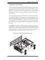
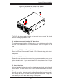
2-4 Installing the System into a Rack
This section provides information on installing the system into a rack unit. Rack
installation requires the use of the optional rackmount kit [CSE-PT26(B)]. If the
system has already been mounted into a rack or if you are using it as a tower, you
can skip ahead to Sections 2-5 and 2-6. There are a variety of rack units on the
market, which may mean the assembly procedure will differ slightly. The following
is a guideline for installing the server into a rack with the rack rails provided in the
rackmount kit. You should also refer to the installation instructions that came with
the rack unit you are using.
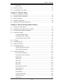
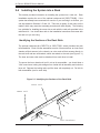
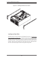
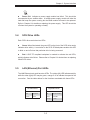
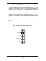
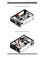
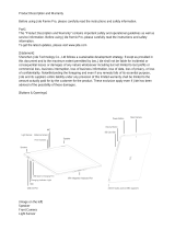
Identifying the Sections of the Rack Rails
The optional rackmount kit (CSE-PT26 or CSE-PT26B - black) includes two rack
rail assemblies. Each of these assemblies consist of three sections: an inner fi xed
chassis rail that secures to the chassis, an outer rack rail that secures directly to
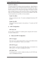
the rack itself and two rail brackets, which also attack to the rack (see Figure 2-1.)
The inner and outer rails must be detached from each other to install.
To remove the inner chassis rail, pull it out as far as possible - you should hear a
"click" sound as a locking tab emerges from inside the rail assembly and locks the
inner rail. Depress the locking tab to pull the inner rail completely out. Do this for
both assemblies (one for each side).
Figure 2-1. Identifying the Sections of the Rack Rails
Inner rail
Outer rail
Rail brackets
Page is loading ...
Page is loading ...
Page is loading ...
Page is loading ...
Page is loading ...
Page is loading ...
Page is loading ...
Page is loading ...
Page is loading ...
Page is loading ...
Page is loading ...
Page is loading ...
Page is loading ...
Page is loading ...
Page is loading ...
Page is loading ...
Page is loading ...
Page is loading ...
Page is loading ...
Page is loading ...
Page is loading ...
Page is loading ...
Page is loading ...
Page is loading ...
Page is loading ...
Page is loading ...
Page is loading ...
Page is loading ...
Page is loading ...
Page is loading ...
Page is loading ...
Page is loading ...
Page is loading ...
Page is loading ...
Page is loading ...
Page is loading ...
Page is loading ...
Page is loading ...
Page is loading ...
Page is loading ...
Page is loading ...
Page is loading ...
Page is loading ...
Page is loading ...
Page is loading ...
Page is loading ...
Page is loading ...
Page is loading ...
Page is loading ...
Page is loading ...
Page is loading ...
Page is loading ...
Page is loading ...
Page is loading ...
Page is loading ...
Page is loading ...
Page is loading ...
Page is loading ...
Page is loading ...
Page is loading ...
Page is loading ...
Page is loading ...
Page is loading ...
Page is loading ...
Page is loading ...
Page is loading ...
Page is loading ...
Page is loading ...
Page is loading ...
Page is loading ...
Page is loading ...
Page is loading ...
Page is loading ...
Page is loading ...
Page is loading ...
Page is loading ...
Page is loading ...
Page is loading ...
Page is loading ...
Page is loading ...
Page is loading ...
Page is loading ...
Page is loading ...
Page is loading ...
-
 1
1
-
 2
2
-
 3
3
-
 4
4
-
 5
5
-
 6
6
-
 7
7
-
 8
8
-
 9
9
-
 10
10
-
 11
11
-
 12
12
-
 13
13
-
 14
14
-
 15
15
-
 16
16
-
 17
17
-
 18
18
-
 19
19
-
 20
20
-
 21
21
-
 22
22
-
 23
23
-
 24
24
-
 25
25
-
 26
26
-
 27
27
-
 28
28
-
 29
29
-
 30
30
-
 31
31
-
 32
32
-
 33
33
-
 34
34
-
 35
35
-
 36
36
-
 37
37
-
 38
38
-
 39
39
-
 40
40
-
 41
41
-
 42
42
-
 43
43
-
 44
44
-
 45
45
-
 46
46
-
 47
47
-
 48
48
-
 49
49
-
 50
50
-
 51
51
-
 52
52
-
 53
53
-
 54
54
-
 55
55
-
 56
56
-
 57
57
-
 58
58
-
 59
59
-
 60
60
-
 61
61
-
 62
62
-
 63
63
-
 64
64
-
 65
65
-
 66
66
-
 67
67
-
 68
68
-
 69
69
-
 70
70
-
 71
71
-
 72
72
-
 73
73
-
 74
74
-
 75
75
-
 76
76
-
 77
77
-
 78
78
-
 79
79
-
 80
80
-
 81
81
-
 82
82
-
 83
83
-
 84
84
-
 85
85
-
 86
86
-
 87
87
-
 88
88
-
 89
89
-
 90
90
-
 91
91
-
 92
92
-
 93
93
-
 94
94
-
 95
95
-
 96
96
-
 97
97
-
 98
98
-
 99
99
-
 100
100
-
 101
101
-
 102
102
-
 103
103
-
 104
104


Supermicro 4020A-8R User manual
- Category
- Server barebones
- Type
- User manual
- This manual is also suitable for
Ask a question and I''ll find the answer in the document
Finding information in a document is now easier with AI
Related papers
-
Supermicro H8DSR-I User manual
-
-
-
-
-
-
-
-
-
Other documents
-
 Rugged Ridge 12104.51 Installation guide
-
 Cables Direct USB-072 Datasheet
-
 Synergy Global Technology RM8006 User manual
-
 StarTech.com 150SCSIBKCAD Datasheet
-
Vantec MRK-300FD-BK User manual
-
 Acrosser Technology AR-IPC14P User manual
-
iStarUSA D-200-PFS Datasheet
-
 Jide Remix Pro Product Description
-
 CEL-MAR ADA-4020A User manual
-
Fujitsu D1419 User manual


