
Leading EDGE COMPUTING
Q7-BT
Technical Reference
Qseven Computer On Module with
Intel
®
Atom™ E3800 Series Processors
Manual Rev.: 2.1
Revision Date: June 18, 2018
Part Number: 50-1Z202-1020

ii Preface
Preface
Disclaimer
Information in this document is provided in connection with ADLINK products. No license,
express or implied, by estoppel or otherwise, to any intellectual property rights is granted by
this document. Except as provided in ADLINK´s Terms and Conditions of Sale for such prod-
ucts, ADLINK assumes no liability whatsoever, and ADLINK disclaims any express or implied
warranty, relating to sale and/or use of ADLINK products including liability or warranties relat-
ing to fitness for a particular purpose, merchantability, or infringement of any patent, copy-
right or other intellectual property right. If you intend to use ADLINK products in or as medical
devices, you are solely responsible for all required regulatory compliance, including, without
limitation, Title 21 of the CFR (US), Directive 2007/47/EC (EU), and ISO 13485 & 14971, if
any. ADLINK may make changes to specifications and product descriptions at any time, with-
out notice.
Trademarks
Product names mentioned herein are used only for identification purposes and may be trade-
marks and/or registered trademarks of their respective companies.
Revision History
© Copyright 2015, 2016, 2017, 2018 ADLINK Technology, Incorporated
This document contains proprietary information protected by copyright. All rights are
reserved. No part of this manual may be reproduced by any mechanical, electronic, or other
means in any form without prior written permission of the manufacturer.
Audience
This manual provides reference only for computer design engineers, including but not limited
to hardware and software designers and applications engineers. ADLINK Technology, Inc.
assumes you are qualified to design and implement prototype computer equipment.
Revision Date Description of Change(s)
1.00 9/21/2015 Initial Release
2.00 8/8/2016 Added changes for A3 board revision
2.1 6/18/2018
Updated pin 3 of SW4 in Table 2-2 from “Not Connected” to “Selecting
BIOS”; added note to pin 3 of SW4 to indicate
BIOS_DISABLE# must
be pulled low; added Figure 1-1 to Chapter 1; added Battery and
Prop 65 warnings to Preface

Preface iii
Q7-BT
Environmental Responsibility
ADLINK is committed to fulfill its social responsibility to global environmen-
tal preservation through compliance with the European Union's Restriction
of Hazardous Substances (RoHS) directive and Waste Electrical and Elec-
tronic Equipment (WEEE) directive. Environmental protection is a top prior-
ity for ADLINK. We have enforced measures to ensure that our products,
manufacturing processes, components, and raw materials have as little
impact on the environment as possible. When products are at their end of
life, our customers are encouraged to dispose of them in accordance with
the product disposal and/or recovery programs prescribed by their nation
or company.
Battery Labels (for products with battery)
California Proposition 65 Warning
WARNING: This product can expose you to chemicals including acrylamide, arse-
nic, benzene, cadmium, Tris(1,3-dichloro-2-propyl)phosphate (TDCPP), 1,4-Diox-
ane, formaldehyde, lead, DEHP, styrene, DINP, BBP, PVC, and vinyl materials,
which are known to the State of California to cause cancer, and acrylamide, benzene, cad-
mium, lead, mercury, phthalates, toluene, DEHP, DIDP, DnHP, DBP, BBP, PVC, and vinyl
materials, which are known to the State of California to cause birth defects or other reproduc-
tive harm. For more information go to www.P65Warnings.ca.gov.
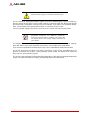
Conventions
The following conventions may be used throughout this manual, denoting special levels of
information.
This information adds clarity or specifics to text
and illustrations.
This information indicates the possibility of minor
physical injury, component damage, data loss,
and/or program corruption.
This information warns of possible serious physi-
cal injury, component damage, data loss, and/or
program corruption.
ᑜ㔚ᳰ⺧࿁ᡴ
NOTE:
CAUTION:
WARNING:

iv Preface
Important Safety Instructions
For user safety, please read and follow all Instructions, WARNINGs, CAUTIONs, and
NOTEs marked in this manual and on the associated equipment before handling/operating
the equipment.
Read these safety instructions carefully.
Keep this manual for future reference.
Read the specifications section of this manual for detailed information on the operating
environment of this equipment.
Turn off power and unplug any power cords/cables when installing/mounting or un-install-
ing/removing equipment.
To avoid electrical shock and/or damage to equipment:
Keep equipment away from water or liquid sources;
Keep equipment away from high heat or high humidity;
Keep equipment properly ventilated (do not block or cover ventilation openings);
Make sure to use recommended voltage and power source settings;
Always install and operate equipment near an easily accessible electrical socket-
outlet;
Secure the power cord (do not place any object on/over the power cord);
Only install/attach and operate equipment on stable surfaces and/or recommended
mountings; and,
If the equipment will not be used for long periods of time, turn off the power source and
unplug the equipment.

v
Q7-BT
Table of Contents
Preface.................................................................................................................................. ii
1 Product Overview............................................................................................................. 1
1.1 Description............................................................................................................................. 1
1.2 Features................................................................................................................................. 2
1.3 Block Diagram........................................................................................................................ 3
1.4 Specifications......................................................................................................................... 4
1.4.1 Physical ............................................................................................................................4
1.4.2 Electrical ............................................................................................................................4
1.4.3 Environmental....................................................................................................................4
1.4.4 Mechanical.........................................................................................................................5
1.4.5 Power.................................................................................................................................6
1.4.6 Cooling .............................................................................................................................6
1.5 Getting Started....................................................................................................................... 7
2 Hardware...........................................................................................................................9
2.1 Major Components (ICs)........................................................................................................ 9
2.2 Connectors, Switches, and LEDs ........................................................................................ 11
2.3 Component Features........................................................................................................... 13
2.3.1 CPU.................................................................................................................................13
2.3.2 Memory............................................................................................................................13
2.3.3 eMMC NAND Flash .........................................................................................................13
2.3.4 SATA SSD (Solid State Drive).........................................................................................14
2.3.5 SMBus Slave Addresses.................................................................................................14
3 Interfaces ........................................................................................................................ 15
3.1 18/24-Bit LVDS LCD ........................................................................................................... 16
3.2 HDMI or Display Port (DP)................................................................................................... 16
3.3 Camera MIPI-CSI................................................................................................................. 16
3.4 Audio (HDA)......................................................................................................................... 16
3.5 PCI Express (PCIe).............................................................................................................. 16
3.6 Gigabit Ethernet .................................................................................................................. 16
3.7 USB Ports............................................................................................................................ 17
3.8 SATA.................................................................................................................................... 17
3.9 I2C Bus................................................................................................................................ 17
3.10 SPI....................................................................................................................................... 17
3.11 Serial (UART)....................................................................................................................... 17
3.12 SD/SDIO Interface............................................................................................................... 17
3.13 eMMC Interface ................................................................................................................... 17
3.14 LPC Debug Interface ........................................................................................................... 17
3.15 MIPI CSI Camera Interface.................................................................................................. 17
3.16 Qseven Interface Signals..................................................................................................... 18
3.17 Debug (DB40) Connector Signals........................................................................................ 25
3.18 MIPI CSI Camera Connector Signals .................................................................................. 26

vi
4 Utilities ............................................................................................................................ 27
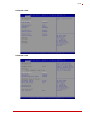
4.1 BIOS.................................................................................................................................... 27
4.1.1 Configuring the BIOS...................................................................................................... 27
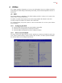
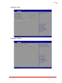
4.1.2 Main screen of the BIOS................................................................................................. 27
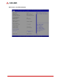
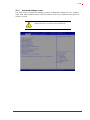
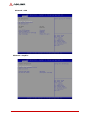
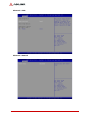
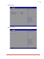
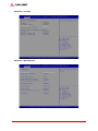
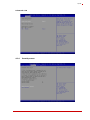
4.1.3 Advanced Settings screen .............................................................................................. 29
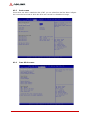
4.1.4 Security screen ............................................................................................................... 37
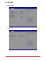
4.1.5 Boot screen..................................................................................................................... 38
4.1.6 Save & Exit screen.......................................................................................................... 38
4.2 SEMA functions................................................................................................................... 39
4.2.1 Board Specific SEMA functions ...................................................................................... 40
4.3 Watchdog Timer.................................................................................................................. 41
4.4 Temperature Sensors ......................................................................................................... 41
4.5 Programming Examples...................................................................................................... 41
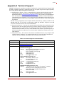
Appendix A Technical Support .........................................................................................43

Product Overview 1
Q7-BT
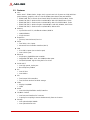
1 Product Overview
1.1 Description
The Q7-BT Computer-On-Module (COM) combines the Qseven
®
2.0 standard with the Intel
®
Atom™ E3800 series System-on-Chip (SoC), providing an ideal solution for mid-range power
and high, pin/area density requirements. The module provides the high integration, high perfor-
mance, low power, and ruggedness favored by Internet-of-Things (IoT) applications such as
retail transactional clients, digital signage, and in-vehicle infotainment systems.
The Qseven form factor affords a more compact profile and footprint than the other COM plat-
forms. With mechanical dimensions as small as 70mm width, 70mm length, and 2.3mm of over-
all height, Qseven ranks as the smallest COM standard currently available.
The Q7-BT module utilizes the E3800 SoC for contemporary, high-bandwidth interfaces such as
PCI Express, USB, Gigabit Ethernet, SATA, and HD Audio. The module generates its own
LVDS, TMDS, and DisplayPort video signals using DDI output from the SoC.
A series of optional eMMC devices offers up to 64GB of on-board NAND Flash storage with an
MMC interface, and an optional SATA, Solid State Drive (SSD) provides up to 64GB of on-board
NAND Flash storage. Two SPI Flash chips implement a fail-safe BIOS, allowing the user to boot
the module even if current BIOS settings have corrupted the system.
Under the management of the BMC chip (Board Management Controller), the SEMA utility
(Smart Embedded Management Agent) provides system control, security, and failure protec-
tion—counting, monitoring, and measuring hardware and software events, and using the
SMBus to send corrective commands to the SoC. The optional SEMA Cloud utility not only con-
trols local events on the module but system client events on the IoT.
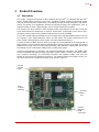
Figure 1-1: Overview of Q7-BT with Intel E-Series SoC
E-Series
Atom
SoC
Qseven
Cooling
Plate
Qseven
Interface
MXM
Connector
MIPI
Camera
Interface

2 Product Overview
1.2 Features
CPU
Intel Atom™ E3800 Series, single, dual, or quad-core SoC (System-on-Chip) with inte-
grated memory, graphics, and I/O. See the E3800 data sheet at the Intel website.
E3845 10W TDP, 1.91GHz Quad-Core/1333 MT/s with Gfx 542/792 MHz, Turbo
E3826 7W TDP, 1.46GHz Dual-Core/1066 MT/s with Gfx 533/667 MHz, Turbo
E3825 6W TDP, 1.33GHz Dual-Core/1066 MT/s with GFx 533/533 MHz, Turbo
E3815 5W TDP, 1.46GHz Single-Core/1066 MT/s with Gfx 400MHz, Non-Turbo
E3805 3W TDP, 1.33GHz Dual-Core/1066 MT/s without GFx
Memory
Up to 4GB non-ECC, unbuffered soldered, DDR3L
1066/1333MHz
Single channel
Expansion
QSeven, board-to-board, Rev 2.0
SATA
Two 3Gb/s, Gen 2 ports
Advanced Host Controller Interface (AHCI)
USB
Six USB 2.0 ports (one as device port)
One USB 3.0 port
Ethernet
Single-port, gigabit Ethernet controller
Integrated GbE MAC, PHY, and SGMII/SerDes ports
10T/100TX/1000T signals using the PCIe x1 bus
Serial UART
One high-speed, 4-wire port
Base frequency 50MHz
I2C
One I2C bus
One SMBus
SPI
Two internal SPI controllers
Two SPI flash devices for BIOS storage
Video
Display Port/HDMI
LVDS
Audio
One HDA (High Definition Audio) interface
CSI/MIPI Camera
One front-end interface for 3 sensors
Capacity for acquiring 1 stream simultaneously from each sensor
Storage
One optional eMMC NAND
One optional SATA SSD

Product Overview 3
Q7-BT
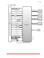
1.3 Block Diagram
Figure 1-2: Module functional block diagram
DDR3L
1066/1333MHz
Qseven Connector (MXM Edge Connector)
Intel®
Bay Trail-I
SoC
DDR3L
Memory
down
2/4GB
PMIC
IDTP9145
DDI1 (DP, TMDS)
HD Audio
3x PCIe x1, PCIe port 1,2,3
1x USB3.0 host
1x (2x) SATA
SDIO x4
Power Management
1x Serial (incl. RTS/CTS)
LAN
i210IT
PCIe x1
GbE
BMC
HWM
SMB
BOOT Select
2x I2C
1x SPI
SPI-
BIOS
SMB
Fan Control
LPC
Debug Connector
for DB40
CSI M IPI
connector
CSI 4L/1L
2x USB2.0 host
Hub
3x USB2.0 host
eMMC
(Option)
eMMC
SATA-SSD
(Option)
SATA
USB PHY
1x USB2.0 client
LVDS
RTD2136
DDI0
LVDS 18/24bit
dual
Q7-BT_blk_diag_c

4 Product Overview
1.4 Specifications
1.4.1 Physical
Table 1-1 lists the physical dimensions of the module.
1.4.2 Electrical
Table 1-2 specifies the electrical characteristics of the module.
1.4.3 Environmental
Table 1-3 defines the environmental conditions under which the module is qualified to operate
and to be stored.
Table 1-4 presents the average times between system failures.
Table 1-1: Weight and Footprint Dimensions
Dimension Measurement
Overall height is measured from the upper board
surface to the top of the highest permanent
component on the upper board surface. This
measurement does not include the cooling solution.
Weight 0.025 kg
[0.09 kg with heat spreader]
Height (overall) 2.29mm
Board thickness 1.27mm
Width 70.00mm
Length
70.00mm
Table 1-2: Electrical Specifications
Parameter Value
Voltage Input
Standard
Standby
RTC
+5 V DC, +/-5%, =/- mV ripple
+5 V standby +/-5%, =/- mV ripple (only needed
for suspend mode)
3.0V, 2.0V to 3.3V (battery), +/-20mV ripple
Power States
C1-C6, S0, S1, S4, S3, S5, S5 ECO mode (wake
on USB S3/S4, WOL S3/S4/S5)
Table 1-3: Temperature, Humidity, and Pressure
Parameter Temperature
Temperature
Standard
Extended
Storage
0°C to +60°C
-40°C to 85°C
-55°C to 85°C
Humidity
Operating
Non-operating
5% to 90% relative humidity, non-condensing
5% to 95% relative humidity, non-condensing
Table 1-4: Mean Time Between Failures
Parameter Value
MTBF at 40°C
278,930 hrs (according to MIL calculation)
MTBF at 85°C
70,119 hrs (according to MIL calculation)

Product Overview 5
Q7-BT
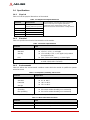
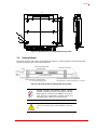
1.4.4 Mechanical
Figure 1-3 provides the mechanical dimensions of the Q7-BT.
Figure 1-3: Mechanical dimensions (top side)
ADLINK strongly recommends plastic spacers
instead of metal spacers for mounting the board.
Metal spacers create the possibilities of short cir-
cuits with the components located around the
mounting holes, which can ruin the board.
Ø
Ø
70
1.2
R0.5
2x R4
53
34
2.5
54
65
70
Q7-BT_mech_dmn_b
21
60
5
2x
4x
6
3
24
8
5
2
62
64
NOTE:

6 Product Overview
1.4.5 Power
Table 1-5 provides the power requirements for this module under certain load configurations.
Operating configurations:
In-rush operating configuration - Windows 8.1
Idle operating configuration - Windows 8.1
BIT (Burn-In Test) operating configuration - Windows 8.1; Intel TAT tool
1.4.6 Cooling
The Q7-BT is designed to operate at its maximum CPU speeds of
1.46GHz and 1.91GHz and
requires a thermal solution to cool the SoC. ADLINK offers a heat spreader as one part of the
cooling solution. Refer to Figure 1-5 for diagram of heat spreader dimensions.
.
Table 1-5: Power Supply Requirements
Parameter
10W, E3845 SoC
Characteristics
7W, E3826 SoC
Characteristics
5W, E3815 SoC
Characteristics
Input Type
Regulated DC voltage Regulated DC voltage Regulated DC voltage
In-rush
Peak Current and
Duration
5V / 1.75A (8.75W) 5V / 1.60A (8.00W) 5V / 1.05A (5.25W)
Typical Idle Current and
Power
5V / 0.86A (4.30W) 5V / 0.79A (3.95W) 5V / 0.62A (3.10W)
BIT
Current and Power
5V / 2.71A (13.55W) 5V / 1.70A (8.95W) 5V / 1.20A (6.00W)
The Q7-BT supports two separate heat spread-
ers—one for board revision A2 and one for board
revision A3. The two versions of the heat spreader
require different order numbers, respectively.
The heat spreader plate requires another form of
cooling, such as a heatsink with a fan. A heat
spreader plate is not a complete thermal solution
for the Q7-BT.
The overall system design must keep the ICs
within their operating temperature specifications.
CAUTION:

Product Overview 7
Q7-BT
Figure 1-4: Heat Spreader mounting dimensions (top side)
1.5 Getting Started
Mount the Q7-BT to the carrier as illustrated in Figure 1-5, which provides a profile view of the
module mounted to the carrier with dimensions.
Figure 1-5: Qseven module mounting dimensions (profile)
ADLINK strongly recommends plastic spacers
instead of metal spacers for mounting the board.
Metal spacers create the possibilities of short cir-
cuits with the components located around the
mounting holes, which can ruin the board
Be sure to observe the EMC security measures. Make
sure you are always at the same potential as the mod-
ule.
Ø
Ø
70
6x M3x5
4x 2.7
4x 5.5
54
65
61
54
48
2.5
30
34
1.4
8
11
1.2
Q7-BT_heat_spreader_dmn_a
Qseven Module PCB
Heatspreader
Qseven Connector
Carrier Borad PCB
Note: Dimension is dependent
on connector height used
All measurements are in millimeters
All dimensions wiothout tolerance +/-0.2mm
See
Note
2.00
1.20
+/-0.1
6.00
NOTE:
CAUTION:

8 Product Overview
Use a commercial, high-quality display cable to connect an HDMI display. Connect a USB key-
board or mouse to the carrier. Use the SATA cable to connect the hard disk. Make sure that the
pins match their counterparts correctly and are not twisted. If you plan to use additional periph-
erals, connect them to the appropriate headers or connectors on the carrier.
Connect a power supply to the power connector on the carrier and switch on the power.
The display shows the BIOS messages. If you want to change the standard BIOS settings,
press the <DEL> key to enter the BIOS setup menus. See Chapter 4 for setup details.
If you need to load the BIOS default values, they can be automatically loaded at boot time.
The Q7-BT boots from CD drives, USB sticks, hard disks, or µSD-Cards. Provided that any of
these is connected and contains a valid operating system image, the display then shows the
boot screen of your operating system.
The Q7-BT needs adequate cooling measures depending on the desired operating temperature
range. Using the board without cooling could damage the board permanently.
Never connect or disconnect peripherals like HDDs
while the power supply is connected and switched on.
Observe the minimum voltage values for the standard
peripherals mentioned. For additional peripherals,
make sure enough power is available. The system will
not work if there is not enough supply current for all
your devices.
CAUTION:
NOTE:

Hardware 9
Q7-BT
2 Hardware
This chapter describes the major integrated circuits (ICs) and interface connectors and headers
on the module. The third section of this chapter further describes the major ICs on the board
including a table of the SMBus slave device addresses on the board.
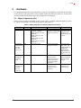
2.1 Major Components (ICs)
Table 2-1 lists the major integrated circuits on the Q7-BT, including a brief description of each
IC. Figure 2-1 and Figure 2-2 show the locations of the major ICs.
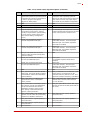
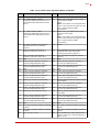
Table 2-1:Major Integrated Circuit Descriptions and Functions
Chip Type Mfg. Model Description Function
CPU (U1) Intel E3805 (dual core, 3W,
headless, 1.33GHz)
E3815 (single core, 5W,
1.46GHz)
E3825 (dual core, 6W,
1.33GHz)
E3826 (dual core, 7W,
1.46GHz)
E3845 (quad core, 10W,
1.91GHz)
Atom, 22nm SoC
(System on Chip) with
Intel 64 architecture
Integrates
Processor Core,
Graphics and
Memory Hub, and
I/O Hub
Gb Ethernet
Controller (U9
on bottom
side; see
Figure 2-2)
Intel WGI210IT SLIXT Single-port Gigabit
Ethernet controller
Integrates GbE
MAC, PHY, and
SGMII/SerDes to
enable 10T/
100TX/1000T
Ethernet signals
using the PCIe x1
bus
BMC [Board
Management
Controller]
(U13)
Renesas UDP78F0763GB-GAH-AX Micro controller for
board functions
including Watchdog
Timer and system
control and failure
protection
Controls dual
BIOS and SEMA
API through the
I
²
C bus
SPI Flash
(U19 and U20
on bottom
side; see
Figure 2-2)
Winbond W25Q64FVSSIG TR Serial Peripheral
Interface Flash
Memory chip (for
firmware)
Stores BIOS 0
and BIOS 1 in
Flash Memory

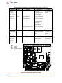
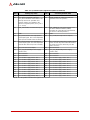
10 Hardware
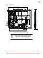
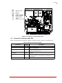
Figure 2-1: Component Locations (Top Side)
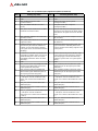
DDR3L
SDRAM
(U24, U25,
U26, U27 [U24
and U27 on
bottom side;
see
Figure 2-2])
Micron
I’M
Intelligent
• MT41K128M16
(1GB board configuration)
• MT41K256M16
(2GB board configuration)
• IM8G16D3FBBG-15EI
(4GB board configuration)
On-board DDR3L,
1.35V, 4Gb,
32Mx16x8, non-ECC
System Memory
• 4Gb, 4x 128Mx16
• 4Gb, 4x 256Mx16
On-board DDR3L,
1.35V, 8Gb,
64Mx16x8, non-ECC
System Memory
• 8Gb, 4x 512Mx16
Provides
high-speed data
transfer
eMMC, NAND
Flash (U48 on
bottom side;
see
Figure 2-2)
Micron MTFC8GLVEA-4M-IT MultiMediaCard
Controller and NAND
Flash Memory up to
64GB
Provides
communication
and mass data
storage
capabilities
SATA NAND
SSD (U73 on
bottom side;
see
Figure 2-2)
[Optional]
Greenliant GLS85LS1008B Industrial-grade
soldered solid-state
storage module
Provides solid
state storage
through SATA 1
port
Table 2-1:Major Integrated Circuit Descriptions and Functions (Continued)
Chip Type Mfg. Model Description Function
Q7-BT_Top_Comp_b
Key:
U1 - CPU
U13 - BMC
U25 - DDR3L SDRAM
U26 - DDR3L SDRAM
U1
U13
U25 U26
P40
P1
P230
P24
P2

Hardware 11
Q7-BT
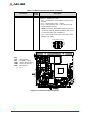
Figure 2-2: Component Locations (Bottom Side)
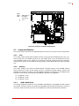
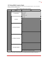
2.2 Connectors, Switches, and LEDs
Table 2-2 describes the connectors, switches, and LEDs shown in Figure 2-3 and Figure 2-4.
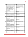
Table 2-2: Module Connector Description
Connector#
Board
Access
Description
CN1 Bottom 40-pin, DB40 Front-Flip connector for debug card
(Molex, 502790-4091)
CN3 Top 40-pin, board-to-FPC connector for MIPI camera interface
(Hirose, DF23C-40DS-0.5V)
GF1 - Q7 Primary and
Secondary
Top/
Bottom
230-pin, MXM edge connector for Memory, Video, and I/O
functions
LED1 Top Blue LED indicating system status activities for HW Reset,
SW Reset, Power Up, Power Down, Reset Button, and
Power Button
LED2 Top Green LED for Power On
P1
P1
P23 P229
U27 U24
U19 U20
U73
U9
U48
Q7-BT_Bot_Comp_b
Key:
U9 - GbE Controller
U19 - BIOS 0
U20 - BIOS 1
U24 - DDR3L SDRAM
U27 - DDR3L SDRAM
U48 - eMMC NAND
Flash
U73 - SSD NAND, SATA

12 Hardware
Figure 2-3: Connector Locations (Top Side)
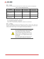
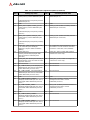
SW4 Top 4-pin dip switch for the following BIOS control functions.
(Diptronics, DHNF-04-T-Q-T/R)
• Pin 1 = Loading BIOS setup defaults at Boot Up (OFF -
default)
• Pin 2 = Enabling WDT (OFF - default)
• Pin 3 = Selecting BIOS (OFF - Fail-safe BIOS1; ON -
Standard BIOS0 [default])
Note: The BIOS_DISABLE# signal on the Q7
connector must be pulled low before Pin 3 can
be used to select Fail-Safe BIOS1.
• Pin 4 = Selecting 18/24 bit LVDS modes (OFF - 18bit
[default]; ON - 24bit)
Table 2-2: Module Connector Description (Continued)
Connector#
Board
Access
Description
ON
(1 2 3 4)
PINS
Q7-BT_SW4_c
Switch Default Settings
Q7-BT_Top_Conn_b
CN3
GF1 - Primary
SW4
P40
P1
P230
P24
P2
Key:
CN3 - MIPI Camera
GF1 - Q7 MXM - Primary
LED1 - System Status (Blue)
LED2 - Power On (Green)
SW4 - BIOS Select
- Pin 1
LED2
LED1

Hardware 13
Q7-BT
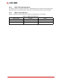
Figure 2-4: Connector Locations (Bottom Side)
2.3 Component Features
This section further describes the supported features of the Q7-BT major on-board components.
2.3.1 CPU
The Q7-BT product family offers multiple versions of the Intel Atom E3800 Series CPU, Sys-
tem-on-Chip (SoC): the E3815 (Single Core), the E3825 (Dual Core), the E3826 (Dual Core),
and the E3845 (Quad Core). E3800 CPUs feature the Intel 64 Architecture and are manufac-
tured based on Intel’s 22-nanometer technology. Refer to the E3800 data sheet at the Intel web-
site.
2.3.2 Memory
The Q7-BT employs one channel of 64-bit DDR3L on-board memory. Four SDRAM memory
chips provide up to 16Gb of low-voltage non-ECC, unbuffered system memory. Refer to the
SDRAM data sheets at the Micron and IM Intelligent websites. Depending on the SDRAM chips
featured on the module, the following total SDRAM capacities are supported:
4x 128M16 = 1 GB
4x 256M16 = 2 GB
4x 512M16 = 4 GB
2.3.3 eMMC NAND Flash
The module supports an optional, on-board eMMC (Multi-Media Card) NAND chip with capacity
up to 64GB. The data signals are routed from the NAND chip through the SDIO pins on the Q7
connector. Refer to the
MTFC8GLDEA-4M-IT NAND Flash data sheet at the Micron website.
P1
P1
P23 P229
CN1
Q7-BT_Bot_Comp_b
Key:
CN1 - DB40 Debug
GF1 - Q7 MXM -
Secondary
- Pin 1
GF1 - Secondary

14 Hardware
2.3.4 SATA SSD (Solid State Drive)
The Q7-BT features an optional SATA SSD, soldered directly to the board and routed through
the SATA1 port. For more information, refer to the SSD data sheet at the Greenliant website.
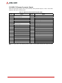
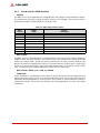
2.3.5 SMBus Slave Addresses
Figure 2-1 lists the corresponding slave addresses of the devices on the SMBus.
Table 2-1: SMBus Slave Addresses
Address (HEX) Function Device
(50) BMC/SEMA BMC
(6A) DP to LVDS RTD2136R
(2C)
7
USB-Hub USB2514Bi
Page is loading ...
Page is loading ...
Page is loading ...
Page is loading ...
Page is loading ...
Page is loading ...
Page is loading ...
Page is loading ...
Page is loading ...
Page is loading ...
Page is loading ...
Page is loading ...
Page is loading ...
Page is loading ...
Page is loading ...
Page is loading ...
Page is loading ...
Page is loading ...
Page is loading ...
Page is loading ...
Page is loading ...
Page is loading ...
Page is loading ...
Page is loading ...
Page is loading ...
Page is loading ...
Page is loading ...
Page is loading ...
Page is loading ...
Page is loading ...
-
 1
1
-
 2
2
-
 3
3
-
 4
4
-
 5
5
-
 6
6
-
 7
7
-
 8
8
-
 9
9
-
 10
10
-
 11
11
-
 12
12
-
 13
13
-
 14
14
-
 15
15
-
 16
16
-
 17
17
-
 18
18
-
 19
19
-
 20
20
-
 21
21
-
 22
22
-
 23
23
-
 24
24
-
 25
25
-
 26
26
-
 27
27
-
 28
28
-
 29
29
-
 30
30
-
 31
31
-
 32
32
-
 33
33
-
 34
34
-
 35
35
-
 36
36
-
 37
37
-
 38
38
-
 39
39
-
 40
40
-
 41
41
-
 42
42
-
 43
43
-
 44
44
-
 45
45
-
 46
46
-
 47
47
-
 48
48
-
 49
49
-
 50
50


Ask a question and I''ll find the answer in the document
Finding information in a document is now easier with AI
Related papers
-
ADLINK Technology LEC-BT Owner's manual
-
-
Adlink DB40-HPC Debug Module Owner's manual
-
-
-
-
-
ADLINK Technology cPCI-3620 Series User manual
-
-
Other documents
-
WinSystems PPM-C407 User manual
-
Sharp PN-CD701 Owner's manual
-
MikroTik RB750 Datasheet
-
AXIOMTEK Q7B301 User manual
-
Eurotech CPU-163-15 Owner's manual
-
Connect Tech PCIe/104 User manual
-
-
-
Molex 503480-0800 User guide
-
DFI FS051 Reference guide