
DISHWASHER
REPAIR
Guide
DISHWASHER
BASIC MODEL : DW60M6050 series
DW60M6040 series
MODEL
NAME : DW60R7070 Series
DW60R7050 Series
DW60R7040 Series
MODEL
CODE : DW60R7070BB DW6KR7071BB
DW60R7070US DW60R7070UW
DW60R7070UG DW60R7050BB
DW6KR7051BB DW60R7050SS
DW6KR7051SS DW60R7050SG
DW60R7050US DW6BR7051US
DW60R7050FS DW60R7050FW
DW60R7040BB DW6KR7041BB
DW60R7040US DW60R7040UW
DW60R7040FS DW60R7040FW
DW6*R70**U* DW6*R70**F*DW6*R70**BB DW6*R70**S*
* For End User.

IMPORTANT SAFETY NOTICE
Following the repair by a non-authorized service provider self-repair or
non-professional repair of the product Samsung is not liable for any
damage to the product any injury or any other product safety issue caused
by any attempt to repair the product which does not carefully follow these
repair and maintenance instructions. Any damage to the product caused by
an attempt to repair the product by any person other than a Samsung
certified service provider will not be covered by the warranty.
All rights reserved.
This service guide may not be reproduced in whole or
as a part in any form whatsoever without the written permission of
the SAMSUNG ELECTRONICS Company.
WARNING
Note
1. You can check where to buy replacement parts at http://samsung.com
2. Visit the part purchase site and enter the model code of your product to check the parts available
for purchase. The model code is labelled on the edge of the tub. When you open the dishwasher’s
door, you can check the model code and version on the barcode label at the left side of the tub.
3. For replacement parts make sure the part name matches that of the illustration in this manual.
-
User-serviceable parts are limited to door hinge and seals other seals spray arms drain lters
interior racks and plastic peripherals such as baskets and lids.
Caution
1. The part name listed on the site may differ from that in this manual. Please make sure you choose
the right part name.
2. Be sure to wear safety gloves while making repairs.
3. Must working more than 2 people to handling heavy weight.

Tools For Removal And Reassembly _ 3
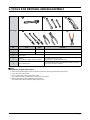
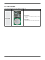
1. TOOLS FOR REMOVAL AND REASSEMBLY
Tool image
No. Tool Type Remarks
①
Adjustable Wrench
②
Open-end Wrench 1-7/16”
③
Vice Pliers
④
Others
(screwdriver, nipper, long nose pliers)
Common tools for servicing
Screwdriver – Phillip, Flat, Torx T15
⑤
Ear clamping tool
In reassembling of the clamp-bend(ear clamp) using our
SVC part, this tool is needed.
NOTE :
Preparation for parts replacement
1. Take out the residual water inside the product. (Drain the water by operating the drain pump)
2. Close the water supply valve.
3. Turn off the power & disconnect power cable.
You must turn off the circuit breaker connected to the product.
4. Pull out the unit from the sink and lay it on the oor.
Be careful of the drain hose when pulling out the unit.

4 _ Standard Disassembly Drawings
2. STANDARD DISASSEMBLY DRAWINGS
2-1. PRECAUTION
Caution
Before servicing,
- Make sure to remove all items include baskets inside dishwasher.
- Drain the water in the dishwasher and disconnect the power supply.
- Lock the water faucet that connected with inlet hose.
- Uninstall the dishwasher from the furniture cabinet except simple work.
- Disconnect the Inlet & Drain hoses from the duct, if the hoses are too short to pull the dishwasher out of the furniture
cabinet enough.
- Make sure to remove any remaining water in the Sump and hoses by rag or vacuum.
→ There is a risk of water spill on the oor.

Standard Disassembly Drawings _ 5
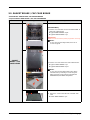
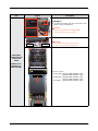
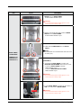
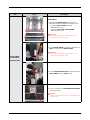
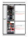
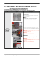
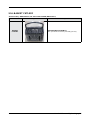
2-2. GASKET BRAKE / CAP CASE BRAKE
- Gasket Brake : DD81-02726A / SVC-GASKET-BRAKE
- Cap Case Brake : DD81-02725A / SVC-CAP CASE BRAKE
Part Figure Description
GASKET
BRAKE / CAP
CASE BRAKE
A
B
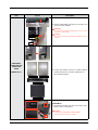
[DISASSEMBLY]
1. Remove 3 screws that connect left SIDE PANEL to
front side of dishwasher.
■ Type A: DD81-02693A / 2 pcs
■ Type B: DD81-02694A / 1 pc
Warning
Be sure to remove the power plug before servicing.
NOTE :
In case of Free Standing models, there’re no
screws of type B.
C
B
2
1
2. Remove 3 screws at the back side of dishwasher.
■ Type C: DD81-02692A / 1 pc
■ Type B: DD81-02694A / 2 pcs
NOTE :
In case of Free Standing models, take off the
COVER TOP by removing 2 screws of type A.
After removing screws, pull the COVER TOP
backward rst, and take it off upward.
Guide Tub Top
3. Remove 1 screw at the left side of GUIDE TUB
TOP.
■ Screw: DD81-02694A / 1 pc

6 _ Standard Disassembly Drawings
Part Figure Description
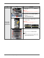
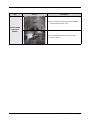
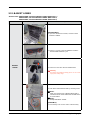
GASKET
BRAKE / CAP
CASE BRAKE
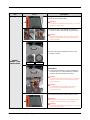
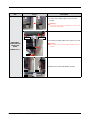
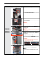
4. Take off the left SIDE PANEL.
Warning
Do not this work without safety gloves. It can cause
injury from sharp edge.
5. Take off the CAP CASE BRAKE by rotating to
counter-clockwise direction with long-nose pliers.
Caution
It can be broken easily when you use iron part of
the pliers. Take off the cap using handle part to
prevent damage.
Cap Case brake
Gasket brake
6. Remove the GASKET BRAKE from the CASE
BRAKE assembly.
[ASSEMBLY]
1. Put the GASKET BRAKE on the CASE BRAKE,
and fasten the CAP CASE BRAKE by rotating to
clockwise direction with long-nose pliers.
Caution
It can be broken easily when you use iron part of
the pliers. Take off the cap using handle part to
prevent damage.
Caution
Pay attention to assemble the seal correctly.
It can cause the water leakage when it’s
assembled wrong.
2. Assemble the left SIDE PANEL with the screws.
Caution
Fasten the screws that was assembled to origin
location. Don’t assemble to other locations.
Warning
Do not this work without safety gloves. It can cause
injury from sharp edge.

Standard Disassembly Drawings _ 7
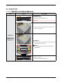
2-3. COVER TOP
- Cover Top : DD81-02552C / SVC-COVER TOP (DW6*R70**FS)
DD81-02552D / SVC-COVER TOP (DW6*R70**FW)
Part Figure Description
COVER TOP
(Only for Free
standing models /
DW6*R70**F*)
[DISASSEMBLY]
1. Release 2 screws.
■ Screws: DD81-02692A / 2 pcs
Warning
Be sure to remove the power plug before servicing.
1
2
2. Pull the COVER TOP backward to release hooks,
and take it off upward.
1
2
Hook Of Cover Top
Guide Of Cover Top
Tub Frame
[ASSEMBLY]
1. Put the COVER TOP on the top of dishwasher, and
push it forward to assembly.
NOTE :
Pay attention to lock the hooks(COVER TOP) to
TUB FRAME.
2. Fasten 2 screws.
■ Screws: DD81-02692A / 2 pcs

8 _ Standard Disassembly Drawings
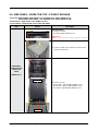
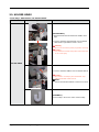
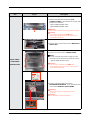
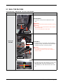
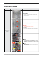
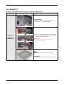
2-4. SIDE PANEL / GUIDE TUB TOP / COVER TUB REAR
- Side Panel : DD81-02880A, DD81-02881A / SVC-HOUSING-LEFT, RIGHT (DW6*R70**FS)
DD81-02880C, DD81-02881C / SVC-HOUSING-LEFT, RIGHT (DW6*R70**FW)
- Guide Tub Top : DD81-02733A / SVC-GUIDE TUB TOP
- Cover Tub Rear : DD81-02734A / SVC-COVER TUB REAR
Part Figure Description
SIDE PANEL/
GUIDE TUB TOP/
COVER TUB
REAR
(DW6*R70**F*)
[DISASSEMBLY]
1. Release 2 screws.
■ Screws: DD81-02692A / 2 pcs
Warning
Be sure to remove the power plug before servicing.
1
2
2. Pull the COVER TOP backward to release hooks,
and take it off upward.
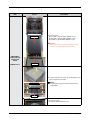
A
B
Cover Tub Rear
B
Guide Tub Top
3. Release Screws.
■ Front side : Type A: DD81-02693A / 4 pcs
■ Rear side : Type B: DD81-02694A / 4 pcs
■ Top side : Type B: DD81-02694A / 2 pcs

Standard Disassembly Drawings _ 9
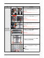
Part Figure Description
SIDE PANEL/
GUIDE TUB TOP/
COVER TUB
REAR
(DW6*R70**F*)
Not to get
stuck
Could be dented
Hook
4. Take the SIDE PANEL off a little, just enough not to
get stuck to TUB FRAME.
Warning
Do not this work without safety gloves. It can cause
injury from sharp edge.
Caution
Be careful not to be dented SIDE PANEL because
of hook.
Side Panel Left
Side Panel Right
Guide Tub Top
Cover Tub Rear
5. Pull the SIDE PANEL off from the COVER PLINTH.
GUIDE TUB TOP and COVER TUB REAR are
disassembled together.
[ASSEMBLY]
1. Assemble the GUIDE TUB TOP and COVER TUB
REAR to back of dishwasher.
Caution
They are not xed without SIDE PANEL.
Recommend to work by 2 people.

10 _ Standard Disassembly Drawings
Part Figure Description
SIDE PANEL/
GUIDE TUB TOP/
COVER TUB
REAR
(DW6*R70**F*)
2. Put the hook of SIDE PANEL into the COVER
PLINTH.
Warning
Do not this work without safety gloves. It can cause
injury from sharp edge.
On The Tub
Frame
On The Guide
Tub Top
Could be dented
Hook
3. Assemble the SIDE PANEL left & right to each side.
Caution
Be careful not to be dented SIDE PANEL because
of hook.
Front
Top
Rear
4. Make sure to t the SIDE PANEL correctly.

Standard Disassembly Drawings _ 11
Part Figure Description
SIDE PANEL/
GUIDE TUB TOP/
COVER TUB
REAR
(DW6*R70**F*)
A
B
Cover Tub Rear
B
Guide Tub Top
5. Fasten Screws.
■ Front side : Type A: DD81-02693A / 4 pcs
■ Rear side : Type B: DD81-02694A / 4 pcs
■ Top side : Type B: DD81-02694A / 2 pcs
Caution
Fasten the screws that was assembled to origin
location. Don’t assemble to other locations.
1
2
Hook Of Cover Top
Guide Of Cover Top
Tub Frame
6. Put the COVER TOP on the top of dishwasher, and
push it forward to assembly.
NOTE :
Pay attention to lock the hooks(COVER TOP) to
TUB FRAME.
7. Fasten 2 screws.
■ Screws: DD81-02692A / 2 pcs

12 _ Standard Disassembly Drawings
- Side Panel : DD81-02928B, DD81-02929B / SVC-HOUSING-LEFT, RIGHT
- Guide Tub Top : DD81-02733A / SVC-GUIDE TUB TOP
- Cover Tub Rear : DD81-02734A / SVC-COVER TUB REAR (DW6*R70**U*, DW6*R70**S*)
DD81-03043A / SVC-COVER TUB REAR (DW6*R70**BB)
Part Figure Description
SIDE PANEL/
GUIDE TUB TOP/
COVER TUB
REAR
(DW6*R70**U*/
DW6*R70**S*/
DW6*R70**BB)
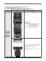
A
B
B
Cover Tub Rear
C
B
Guide Tub Top
[DISASSEMBLY]
1. Release Screws.
■ Front side (Type A): DD81-02693A / 4 pcs
(Type B): DD81-02694A / 2 pcs
■ Rear side (Type B): DD81-02694A / 4 pcs
(Type C): DD81-02692A / 2 pcs
■ Top side (Type B): DD81-02694A / 2 pcs
Side Panel Left
Side Panel Right
Guide Tub Top
Cover Tub Rear
2. Disassemble the SIDE PANEL left & right from
each side. GUIDE TUB TOP and COVER TUB
REAR are disassembled together.
Warning
Do not this work without safety gloves. It can cause
injury from sharp edge.

Standard Disassembly Drawings _ 13
Part Figure Description
SIDE PANEL/
GUIDE TUB TOP/
COVER TUB
REAR
(DW6*R70**U*/
DW6*R70**S*/
DW6*R70**BB)
[ASSEMBLY]
1. Assemble the GUIDE TUB TOP and COVER TUB
REAR to back of dishwasher.
Caution
They are not xed without SIDE PANEL.
Recommend to work by 2 people.
On The Tub
Frame
On The Guide
Tub Top
2. Assemble the SIDE PANEL left & right to each side.
Warning
Do not this work without safety gloves.
It can cause injury from sharp edge.
A
B
B
Cover Tub Rear
C
B
Guide Tub Top
3. Fasten screws.
■ Front side
(Type A): DD81-02693A / 4 pcs
(Type B): DD81-02694A / 2 pcs
■ Rear side
(Type B): DD81-02694A / 4 pcs
(Type C): DD81-02692A / 2 pcs
■ Top side
(Type B): DD81-02694A / 2 pcs

14 _ Standard Disassembly Drawings
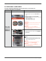
2-5. HOLDER HINGE
- Holder Hinge : DD81-02763A / SVC-HOLDER HINGE
Part Figure Description
HOLDER HINGE
[DISASSEMBLY]
* PREPARATION: Disassemble SIDE PANEL left &
right.
1. Remove HOLDER ROPE DOOR from the DOOR
HINGE left & right with the DOOR closed.
Warning
Be sure to remove the power plug before servicing.
Caution
Pay attention to DOOR drop after remove the rope.
It can cause injury.
2. Remove HOLDER HINGE from the DOOR HINGE.
Caution
Be careful to avoid injury from the DOOR drop
without HOLDER ROPE DOOR.
NOTE :
Rotate the HOLDER HINGE to release from hook.
[ASSEMBLY]
* Reassembly is the reverse order of disassembly.

Standard Disassembly Drawings _ 15
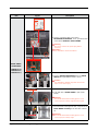
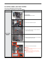
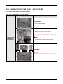
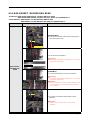
2-6. DOOR HINGE / GUIDE HINGE
- Door Hinge : DD82-01675A, DD82-01676A / SVC ASSY-HINGE-RIGHT, SVC ASSY-HINGE-LEFT
- Guide Hinge : DD81-02837A / SVC-GUIDE HINGE
Part Figure Description
DOOR HINGE /
GUIDE HINGE
(DW6*R70**F*/
DW6*R70**U*/
DW6*R70**S*)
B B
A
A
B
[DISASSEMBLY]
※ PREPARATION: Disassemble SIDE PANEL left &
right.
1. Remove 10 screws that connect the ASSY
CONTROL PANEL to the dishwasher’s DOOR with
Torx® T15 screwdriver.
- Type A: DD81-03011A / 6 pcs
- Type B: DD81-02758A / 4 pcs
Warning
Be sure to remove the power plug before servicing.
Caution
Make sure to Remove the power plug before
servicing.
Caution
The screws can fall into the SUMP after
disassembly. Keep the screws to other place to
reassemble the DOOR.
2. Remove the wire harness that connect MAIN PBA to
TOUCH PBA.
C
3. Remove 4 screws to take off DOOR OUTER.
NOTE :
Screws on DOOR are Torx® T15 type. Use the
Torx® T15 screw driver when release the screws.
- Type C: DD81-02757A / 4 pcs
Caution
Be careful to avoid injury when the DOOR is
closed after remove DOOR OUTER.
Caution
The screws can fall into the SUMP after
disassembly.Keep the screws to other place to
reassemble the DOOR.

16 _ Standard Disassembly Drawings
Part Figure Description
DOOR HINGE /
GUIDE HINGE
(DW6*R70**F*/
DW6*R70**U*/
DW6*R70**S*)
Hook
Hook
4. Remove 2 terminals that connected to
DETERGENT DISPENSER, and 1 ground wire that
connected to BRACKET DOOR FRAME.
Warning
Be sure to remove the power plug before
servicing.
Caution
Pay attention to hook of terminals.
5. Remove HOLDER ROPE DOOR from the DOOR
HINGE left & right with the DOOR closed.
Caution
Pay attention to DOOR drop after remove the
rope. It can cause injury.
GUIDE
HINGE
6. Push both ribs of GUIDE HINGE to pull out the
DOOR.
Warning
Do not this work without safety gloves. It can
cause injury from sharp edge of broken parts.
About 15˚
7. Do same work at the opposite side, and pull out the
DOOR INNER assembly to the direction of about
15˚.
Warning
Do not this work without safety gloves. It can
cause injury from sharp edge.

Standard Disassembly Drawings _ 17
Part Figure Description
DOOR HINGE /
GUIDE HINGE
(DW6*R70**F*/
DW6*R70**U*/
DW6*R70**S*)
8. Remove 2 screws to take off BRACKET DOOR
FRAME from the DOOR INNER.
- Screws: DD81-02728A / 2 pcs
Warning
Do not this work without safety gloves. It can
cause injury from sharp edge.
9. Remove 2 screw at each side to take off DOOR
HINGE from the DOOR INNER.
- Screws: DD81-02764A / 4 pcs
10. Take off the GUIDE HINGE from the DOOR
HINGE.
NOTE :
DOOR HINGE and GUIDE HINGE will serviced to
assembly only.
[ASSEMBLY]
1. Assemble the DOOR HINGE assembly and
BRACKET DOOR FRAME with machine screws.
- Screws for DOOR HINGE assembly :
DD81-02764A / 4 pcs
- Screws for BRACKET DOOR FRAME :
DD81-02728A / 2 pcs
Warning
Do not this work without safety gloves. It can
cause injury from sharp edge.
About 15˚
2. Put the DOOR INNER assembly into the holder of
TUB to lock the hook of DOOR HINGE.
Warning
Do not this work without safety gloves. It can
cause injury from sharp edge.

18 _ Standard Disassembly Drawings
Part Figure Description
DOOR HINGE /
GUIDE HINGE
(DW6*R70**F*/
DW6*R70**U*/
DW6*R70**S*)
3. Put the HOLDER ROPE DOOR on the both side of
DOOR HINGE with the DOOR closed.
4. Connect 2 terminals of DETERGENT DISPENSER,
and 1 ground wire.
Caution
Make sure the Wire harness are not getting stuck
in other parts.
5. Connect wire terminal to connect MAIN PBA to
TOUCH PBA.
Caution
Make sure the Wire harness are not getting stuck
in other parts.
B
B
A
6. Fix 8 screws to connect the ASSY CONTROL
PANEL to the dishwasher’s DOOR with Torx® T15
screwdriver.
- Type A: DD81-03011A / 6 pcs
- Type B: DD81-02758A / 2 pcs
2
1
7. Assemble the holes of DOOR OUTER to hooks of
CONTROL PANEL.
Warning
Do not this work without safety gloves. It can
cause injury from sharp edge.
Holes of DOOR OUTER Hooks of CONTROL PANEL
C
C
B
B
8. Fasten 8 screws to x the DOOR OUTER.
NOTE :
Screws on DOOR are Torx® T15 type. Use the
Torx® T15 screw driver when release the screws.
- Type B: DD81-02758A 4 pcs
- Type C: DD81-02757A 4 pcs

Standard Disassembly Drawings _ 19
Part Figure Description
DOOR HINGE /
GUIDE HINGE
(DW6*R70**BB)
B
A
[DISASSEMBLY]
1. Remove 8 screws that connect the ASSY
CONTROL PANEL to the dishwasher’s DOOR with
Torx® T15 screwdriver.
- Type A: DD81-02756A / 2 pcs
- Type B: DD81-02758A / 6 pcs
Warning
Be sure to remove the power plug before servicing.
Caution
The screws can fall into the SUMP after
disassembly
. Keep the screws to other place to
reassemble the DOOR.
2. Remove wire connector that connect MAIN PBA to
TOUCH PBA.
C
3. Remove 6 screws to take off DOOR OUTER.
NOTE :
Screws on DOOR are Torx® T15 type. Use the
Torx® T15 screw driver when release the screws.
- Type C: DD81-02757A / 6 pcs
Caution
The screws can fall into the SUMP after
disassembly. Keep the screws to other place to
reassemble the DOOR.
Hook
Hook
4. Remove 2 terminals that connected to
DETERGENT DISPENSER, and 1 ground wire that
connected to BRACKET DOOR FRAME.
Warning
Be sure to remove the power plug before
servicing.
Caution
Pay attention to hook of terminals.

20 _ Standard Disassembly Drawings
Part Figure Description
DOOR HINGE /
GUIDE HINGE
(DW6*R70**BB)
5. Remove HOLDER ROPE DOOR from the DOOR
HINGE left & right with the DOOR closed.
Caution
Pay attention to DOOR drop after remove the
rope. It can cause injury.
GUIDE
HINGE
6. Push both ribs of GUIDE HINGE to pull out the
DOOR.
Warning
Do not this work without safety gloves. It can
cause injury from sharp edge of broken parts.
About 15˚
7. Do same work at the opposite side, and pull out the
DOOR INNER assembly to the direction of about
15˚.
Warning
Do not this work without safety gloves. It can
cause injury from sharp edge.
8. Remove 2 screws to take off BRACKET DOOR
FRAME from the DOOR INNER.
- Screws: DD81-02728A / 2 pcs
Warning
Do not this work without safety gloves. It can
cause injury from sharp edge.
9. Remove 2 screw at each side to take off DOOR
HINGE from the DOOR INNER.
- Screws: DD81-02764A / 4 pcs
10. Take off the GUIDE HINGE from the DOOR
HINGE.
NOTE :
DOOR HINGE and GUIDE HINGE will serviced to
assembly only.
Page is loading ...
Page is loading ...
Page is loading ...
Page is loading ...
Page is loading ...
Page is loading ...
Page is loading ...
Page is loading ...
Page is loading ...
Page is loading ...
Page is loading ...
Page is loading ...
Page is loading ...
Page is loading ...
Page is loading ...
Page is loading ...
Page is loading ...
-
 1
1
-
 2
2
-
 3
3
-
 4
4
-
 5
5
-
 6
6
-
 7
7
-
 8
8
-
 9
9
-
 10
10
-
 11
11
-
 12
12
-
 13
13
-
 14
14
-
 15
15
-
 16
16
-
 17
17
-
 18
18
-
 19
19
-
 20
20
-
 21
21
-
 22
22
-
 23
23
-
 24
24
-
 25
25
-
 26
26
-
 27
27
-
 28
28
-
 29
29
-
 30
30
-
 31
31
-
 32
32
-
 33
33
-
 34
34
-
 35
35
-
 36
36
-
 37
37


Ask a question and I''ll find the answer in the document
Finding information in a document is now easier with AI
Related papers
-
Samsung DW6KR7051BB User manual
-
Samsung DW50R4071BB User manual
-
Samsung DW60M5050FW/EC User manual
-
Samsung DW60A8050FB User guide
-
Samsung DW60M6050FS/EU User manual
-
Samsung DW60M5042FS User guide
-
Samsung DW60A6092FS User guide
-
Samsung DW60A6082BB User manual
-
Samsung DW50R4050BB User manual
-
Samsung DW60A8070US User manual
Other documents
-
Lenovo G34w-30 Owner's manual
-
Hotpoint GSD2600G20CC Installation guide
-
Sega DLX User manual
-
RTS Aio-8bc-scsi2 User manual
-
LG WM2411HW User manual
-
LG Electronics WD-10PFD User manual
-
Braun 403 User manual
-
LG WD-10124RD User manual
-
-
Electrolux EIDW6105GS1 Technical & Service Manual