Page is loading ...

Introduction
1
Copyright
Copyright © 2000 by AOpen Inc. All rights reserved.
No part of this document may be copied or reproduced in any form or by any means without
the prior written consent of AOpen Inc.
AOpen makes no warranties with respect to this documentation and disclaims any implied
warranties of merchantability, quality, or fitness for any particular purpose. The information
in this document is subject to change without notice. AOpen reserves the right to make
revisions to this publication without obligation to notify any person or entity of any such
changes.
AOpen
®
is a registered trademark of AOpen Inc. Other trademarks or brand names mentioned herein
are trademarks or registered trademarks of their respective owners.

Table of Contents
1. Introduction........................................................................... 1-1
1.1. Configuration.....................................................................................1-2
1.2. Features ............................................................................................1-3
2. Parts Description..................................................................2-1
2.1. Front Cover and Front Panel.............................................................2-2
2.1.1. Front Cover............................................................................2-2
2.1.2. Front panel.............................................................................2-3
2.2. Back Panel ........................................................................................2-4
2.2.1. Power Supply.........................................................................2-4
2.2.2. I/O Ports.................................................................................2-5
2.2.3. Expansion Slots......................................................................2-5
2.2.4. Housing Fans.........................................................................2-5
2.3. Main Body .........................................................................................2-6
2.4. Cooling System .................................................................................2-7
2.5. Security Device..................................................................................2-8
2.6. Power Supplies..................................................................................2-9
2.6.1. Standard ATX 12V power supply ...........................................2-9
2.6.2. Redundant 337W Power Supply.........................................2-13
2.7. Drive Bays.......................................................................................2-18
3. Installation............................................................................. 3-1
3.1. Opening Chassis...............................................................................3-1
3.2. Installing Motherboard into Chassis...................................................3-2
3.3. Fastening Slide Rails to FDD and 5.25” CD-ROM.............................3-3
3.4. Installing FDD and 5.25” CD-ROM into Chassis................................3-4
3.5. Installing HDD Cage into Chassis......................................................3-5
3.6. Final Assembly..................................................................................3-6
3.7. Rack Mount Placement .....................................................................3-7
3.8. Explosive View, parts and icon..........................................................3-8
3.8.1. Explosive view........................................................................3-8
3.8.2. parts......................................................................................3-8
3.8.3. accessory box.....................................................................3-10
3.8.4. icon .....................................................................................3-10
4. Optional Parts Lists.............................................................. 4-1
4.1. WH (wheels and Handle) kit (Optional) .............................................4-1
4.2. Rack Mount Assembly kit..................................................................4-2
5. Technical Support................................................................5-1
5.1. How to Get Technical Support...........................................................5-1
5.2. How to contact us..............................................................................5-1

Introduction
1-1
1. Introduction
The H800 is a user-friendly server chassis that has been tested and found to be complied
with the restrictions for a Class B device of the FCC Rules, CE, C tick and all EMC
requirements. Any accessing, upgrading and maintenance operation to the system can be
easily performed and done.
This server chassis supports the motherboard form factor of Baby AT, Full ATX & AT, and
SSI defined which can be integrated into a standalone or standard 19” rack mount, thus
greatly enlarge its working field.
This server chassis combines affordability, reliability, and expendability that totally meet
your professional needs. The 1.0mm heavy-duty zinc-plated steel is robust and can
effectively protect all components inside. The security system forbids all unauthorized
intrusions. One standard 8cm powerful cooling fan (expandable to two 8cm fans) provides
excellent ventilation to the chassis.
User’s Guide

Introduction
1-2
1.1. Configuration
Dimension:
(H x W x D)
Front panel, foot stand excluded:
16.93 x 8.58 x 21.65 in. (430 x 218 x 550 mm),
Front panel, foot stand included:
17.72 x 8.58 x 23.43 in. (450 x 218 x 595 mm)
Motherboard
Size:
(W x L)
Support to 12 x 13 in. (305 x 330 mm)
Baby AT, Full ATX & AT, and SSI M.B.
Drive Bays: Nine external 5.25” drive, one FDD, one HDD cage.
(2*5.25” can support 3 HDD)
Expansion Slots: 7 slots
Power Supply: 350W/400W ATX12V power supply, or redundant 337W
(with or without 2
nd
power)
Security: Chassis intrusion alarm
Mechanical key lock on front panel (locking all
components with one key)
Thermal Solution: One built-in 8 cm fan on back panel (one optional 8cm fan
is available)
One optional 8 cm fan on front side (installed along with
HDD cage)
Rack Mounting: 5U Supporting
Air Filter Support one air filter on front panel
I/O port bracket Support one I/O port bracket for standard ATX M.B.
FDD Support 1 FDD with FDD cable
Long card Guide Support 2 sets of long card guide
Optional Hand set & Wheel
Rack mount accessory kit
BPL6: support 6 pcs Hot swap SCSI HDD
H800 Server Chassis

Introduction
1-3
1.2. Features
User’s Guide

Introduction
1-4
Redundant power supply: 337W (with or without 2
nd
power)
Standard ATX 12V power supply: 350 / 400W ATX power supply
Rack mount assembly kit (optional)
Support 5U rack mount accessories
Hot swap HDD cage (optional)
BPL6: Support 6pcs Hot swap SCSI HDD (4 x 5.25” changeable to 6 x
3.5” HDD)
Chassis key lock and Key set
Support key lock solution to provide security solution
Air filter
Supporting air filtering
HDD cage for three 3.5” HDD and one optional 8 cm fan
2 x 5.25” is spacious enough to support 3 x HDD and 1 optional 8cm fan
with slide rails solution
Disk drive bay installed by screw or slide guide
10pcs slide guides for the installation of 5.25” devices (including HDD
cage)
Optional wheel and hand set makes it incredibly mobile
One built-in 8 cm fan (one more optional 8cm fan available)
H800 Server Chassis

Parts Description
2-1
2. Parts Description
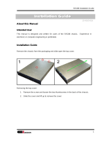
The H800 is designed to maximize the extension ability of the system for you to access,
upgrade, and maintain it.
The H800 is consist of:
Front Cover and Front Panel
Back Panel
Main Body
Cooling System
Security Device
Power Supplies
Drive Bays
User’s Guide

Parts Description
2-2
2.1. Front Cover and Front Panel
The H800 is designed with a key lock on the door to protect against inadvertent access to
the power button, reset button, and disk drives.
Behind the door are mountings for nine 5.25” and one 3.5” drive bays, one Power button,
one Reset button, one Intrusion Alarm Detector, and three LED indicators.
2.1.1. Front Cover
Key Lock:
Ke
y
This is a mechanical key lock,
which lock all components inside
the door. The H800 provides one
set key & key lock function for
system security to ensure the
safety of high-end system
components inside.
Key
Air Filter:
This air-filter screen is being attached to the inner
side of the front cover to avoid the short circuit of
system components caused by dusts.
Air filter
H800 Server Chassis

Parts Description
2-3
2.1.2 Front panel
Drive Bays:
Reset Knob
HDD LED
System Status LED
Power LED
Power Knob
3.5-inch Drive Bays
The H800 is designed with nine
5.25” drive bays and one 3.5”
drive bays. You can occupy the
space of two 5.25” drive bays
with one standard HDD cage;
and the space of HDD cage can
be occupied with three 3.5” IDE
HDD likewise. The Drive Bays
can be easily arranged based on
your needs to have the best
system performance.
5.25-inch
Drive Bays
HDD Cage
Power Knob:
Press the power knob to boot the system.
Reset Knob:
Press the Reset knob to reset the system.
LED Indicators:
There are three LED on the lower right side of the front panel indicating the status of
(1) Power LED - green, (2) Hard Disk Drive - orange, and (3) System Status - yellow.
Intrusion Alarm Detector:
This micro switch is used to detect the opening of front cover and only works when
connected to motherboard. Please check you MB manual then install this connector into
MB.
P/N: 50.93301.001
Intrusion Alarm
User’s Guide

Parts Description
2-4
2.2. Back Panel
There are four components available to be installed on the back panel of H800: (1) Power
Supply, (2) I/O Ports, (3) Expansion Slots, and (4) Housing Fans.
2.2.1 Power Supply
The H800 provides 2 solutions:
1. Standard ATX 12V 350W/400W power supply : you have to assemble this standard ATX
12V power together with the power bracket before installed to chassis.
b
Power Bracket
Standard ATX 12V
350/400W
2. Redundant 337W power supply (with or without 2
nd
power)
337W Redundant
Power Cage
337W main power
2
n
d
redundant 337W power
(optional)
H800 Server Chassis

Parts Description
2-5
2.2.2 I/O Ports
The H800 provides standard
ATX ports bracket, which
meets the standard definition
of PC99. For detail output,
please see the following
diagram:
2.2.3. Expansion Slots
All of the I/O signals go through the ATX I/O ports; and there’re 7 expansion slots at the rear
panel in total.
2.2.4. Housing Fans
The H800 has a built-in 8cm FAN and one optional 8cm FAN on its back panel. Besides, it
reserves another space for one 8cm FAN on the front panel, which can be placed together
with HDD cage.
Redundant power supply (optional)
Redundant power supply x1 pcs
Standard FAN x1 pcs
A
ddition FAN (optional)
I/O port bracket
Expansion slots x7
User’s Guide

Parts Description
2-6
2.3. Main Body
The H800 provides a strong structure and impediment-free design for easy assembly.
Long Card Guide x2 pcs
9x5.25” drive
Sliding in or screwing for components
assembly
MB size: supports up to 12x13” MB
with Pentium4 CPU mounting holes
MB type: SSI, Full ATX, AT & Baby AT
Foot for stand-alone
Long Card Guide x2 pcs
P/N: 42.96501.011
H800 Server Chassis

Parts Description
2-7
2.4. Cooling System
The H800 is equipped with one 8cm fan at the rear panel, and is also possible to add one
more optional 8cm fan to make it a two-fan cooling system.
There is one more optional way of adding another 8cm fan to the 3.5” HDD cage located at
front panel.
All fans are hot swappable, allowing users to replace malfunctioning fans without turning off
the system.
If you want to install one more 8cm fan, you
must take out the fan cover first.
g
g
Put the fan into HDD cage, screw it on,
and then arrange the fan cable.
User’s Guide

Parts Description
2-8
2.5. Security Device
The H800 has one mechanical key lock on the front panel cover and one electrical chassis
intrusion alarm to prevent unauthorized access to components inside the chassis.
The chassis intrusion alarm is an electrical detecting device that came with the
motherboard. It will alarm whenever the front panel or side panels are opened. The overall
security system protects this server chassis perfectly.
Key lock for system security
H800 Server Chassis

Parts Description
2-9
2.6. Power Supplies
The H800 supports standard ATX 12V and redundant 337W (with or without 2
nd
power)
power supplies.
2.6.1 Standard ATX 12V power supply
Before Assembly standard ATX 12V power supply, it must assemble power bracket with
power than can install to chassis.
b
Power Bracket
Standard ATX 12V
350/400W
Standard
ATX
2.6.1.1. 350W ATX 12V Power Supply Specification
GENERAL REQUIREMENTS
This specification describes a 350 watts power supply.
With + 5V stand-by and remote ON/OFF control for ATX system.
User’s Guide

Parts Description
2-10
INPUT REQUIREMENTS
The power supply shall operate from 95 to 132 Vrms or 180 to 264 Vrms.
The power supply shall operate from an AC mains frequency of 47 through 63 Hz.
The Ac mains single-cycle peak inrush current shall be limited to 80 amps cold,
100 amps warm measured at 132 Vrms, 60 Hz and coinciding with the AC main
voltage peak.
The AC mains steady-state RMS input current shall be:
10 amps maximum / 115 Vrms, 60 Hz.
5.0 amps maximum / 230 Vrms, 50 Hz.
OUTPUT REQUIREMENTS
OUTPUT VOLTAGE AND CURRENT
MINIMUM
LOAD
NORMAL
LOAD
MAXIMUM
LOAD
LOAD
REG.
RIPPLE & NOISE
+3.3V 0.2A 14.0A 18/28A
5%
50mV P-P
+5V 2.0A 12.7A 32/25.5A
5%
50mV P-P
+12V 0.2A 4.5A 15.0A
5%
120mV P-P
-12V 0.0A 0.4A 0.8A
10%
120mV P-P
-5V 0.0A 0.15A 0.3A
10%
100mV P-P
+5Vsb 0.0A 1.0A 2.0A
5%
50mV P-P
(1). +3.3V &+5V total output not exceed 220W.
When +3.3V is load to 28A,the +5V maximum load is 25.5A.
When +3.3V is load to 18A,the +5V maximum load is 32A.
(2). +3.3V &+5V & +12V total output not exceed 330W.
(3) All outputs shall be safety-isolated from the AC mains and share a common
return. This common return must be connected to supply chassis.
(4) Voltages and ripple are measured at the load side of mating connectors with
a 0.1 uF monolithic ceramic capacitor paralleled by a 10 uF electrolytic
capacitor across the measuring terminals.
REGULATORY COMPLIANCE
SAFETY REQUIREMENTS
-CSA C22.2
-UL 1950
-IEC 950
-TUV EN 60950
-NEMKO + CB REPORT
DIELECTRIC STRENGTH
-Primary to Frame Ground : 1800 Vac for 1 sec.
H800 Server Chassis

Parts Description
2-11
-Primary to Secondary : 1800 Vac for 1 sec.
INSULATION RESISTANCE
-Primary to Secondary : 20 Meg. ohms Minimum.
-Primary to FRAME GROUND : 20 Meg. ohms Minimum.
GROUND LEAKAGE CURRENT
-The power supply ground leakage current shall be less than 3.5mA.
EMISSION REQUIREMENTS
-When testing the power supply must operate within the listed requirements.
OTHER REQUIREMENTS
COOLING
With the fan voltage set to around 12 volts, the fan will deliver greater than 38
CFM with the power supply in open air.
INPUT CONNECTIONS
Refer to Mechanical Specifications for placement. The AC mains input are
through a three-circuit IEC type connector mounted on the rear of the power
supply chassis.
RELIABILITY
The power supply reliability, when calculated by MIL-HDBK-217; latest
revision, are exceed 100.000 hours with all output at maximum load and an
ambient temperature of 25 .
2.6.1.2. 400W ATX 12V Power Supply Specification
GENERAL REQUIREMENTS
This specification describes a 400 watts power supply.
With + 5V stand-by and remote ON/OFF control for ATX system.
INPUT REQUIREMENTS
-The power supply shall operate from 95 to 132 Vrms or 180 to 264 Vrms.
-The power supply shall operate from an AC mains frequency of 47 through 63
Hz.
-The Ac mains single-cycle peak inrush current shall be limited to 80 amps cold,
100 amps warm measured at 132 Vrms, 60 Hz and coinciding with the AC
main voltage peak.
-The AC mains steady-state RMS input current shall be:
10 amps maximum / 115 Vrms, 60 Hz.
6.0 amps maximum / 230 Vrms, 50 Hz.
User’s Guide

Parts Description
2-12
OUTPUT REQUIREMENTS
OUTPUT VOLTAGE AND CURRENT
MINIMUM
LOAD
NORMAL
LOAD
MAXIMUM
LOAD
LOAD
REG.
RIPPLE &
NOISE
*+3.3V 0.2A 14.0A 10.6/28A
5%
50mV P-P
+5V 2.0A 14.0A 40/28.5A
5%
50mV P-P
+12V 0.2A 6.0A 15A
5%
120mV P-P
-12V 0.0A 0.4A 0.8A
5%
100mV P-P
-5V 0.0A 0.15A 0.3A
5%
100mV P-P
+5Vsb 0.0A 1.0A 2.0A
5%
50mV P-P
*OPTIONAL
(1) +3.3V &+5V total output not exceed 235 W.
When +3.3V is load to 28A,the +5V maximum load is 28.5A.
When +3.3V is load to 10.6A,the +5V maximum load is 40A.
(2) +3.3V &+5V & +12V total output not exceed 330 W.
(3) All outputs shall be safety-isolated from the AC mains and share a common
return. This common return must be connected to supply chassis.
(4 )Voltages and ripple are measured at the load side of mating connectors with a
0.1 uF monolithic ceramic capacitor paralleled by a 10 uF electrolytic capacitor
across the measuring terminals.
REGULATORY COMPLIANCE
SAFETY REQUIREMENTS
-CSA C22.2
-UL 1950
-IEC 950
-TUV EN 60950
-NEMKO + CB REPORT
DIELECTRIC STRENGTH
-Primary to Frame Ground : 1800 Vac for 1 sec.
-Primary to Secondary : 1800 Vac for 1 sec.
INSULATION RESISTANCE
-Primary to Secondary : 20 Meg. ohms Minimum.
-Primary to FRAME GROUND : 20 Meg. ohms Minimum.
GROUND LEAKAGE CURRENT
The power supply ground leakage current shall be less than 3.5mA.
EMISSION REQUIREMENTS
H800 Server Chassis

Parts Description
2-13
When testing the power supply must operate within the listed requirements.
OTHER REQUIREMENTS
COOLING
With the fan voltage set to around 12 volts, the fan will deliver greater than 38 CFM
with the power supply in open air.
INPUT CONNECTIONS
Refer to Mechanical Specifications for placement.
The AC mains input are through a three-circuit IEC type connector mounted on the
rear of the power supply chassis.
RELIABILITY
The power supply reliability, when calculated by MIL-HDBK-217; latest revision,
are exceed 100.000 hours with all output at maximum load and an
2.6.2. Redundant 337W Power Supply
The redundant 337W power comes with power cage, 337W main power & 2nd 337W main
power (optional)
337W Redundant
power cage
Main power
module
337W main power
X 2 pcs
337W main power
User’s Guide

Parts Description
2-14
Support
Redundant
337W x 2
1 x 337W
Main power only
2.6.2.1. DPS-300AB-1A 337W redundant Main power module specification
General description :
This specification describes the performance characteristic of 337 watts Hot-swap
redundant power unit with +5V, +12V,+3.3V,-5V and –12V DC outputs.
Forced output current share : the SPS unit(DPS-300AB-1) is intended to work with cage
unit(RPS-600A) to form a redundant power module.
There are two configurations described as below :
(1) One single power supply operation,
It is configured as one cage unit ( Delta module name RPS-600A) compatible with one
power supply unit ( Delta model name DPS-300AB-1) for single power supply
operation
(2) Dual power supplies redundant operation,
It’s configured with one cage unit ( RPS-600A) compatible with two units of power
supply (DPS-300AB-1) for dual power supply current sharing operation.
Under dual power supply redundant operation, the power supply’s output current are
controlled electronically so that both power supplies share the loads.
Electrical Characteristics :
(1) Input voltage range: 90 Vac ~ 264 Vac, auto-range, single phase
(2) Input frequency range: 47 Hz to 63 Hz.
(3) Max. input AC current: 7 Amax. @ 115 Vac, 3.5A max. @ 230 Vac, full load
(4) Inrush current of this module shall not exceed 60 amperes peak at 100 vrms input
voltage, the inrush current measured at cold start.
(5) Efficiency: 63% min. At low line 110/220 VAC (60Hz) full load.
(6) Power Factor Correction : the power module (RPS-600A compatible with
H800 Server Chassis
/