Page is loading ...

Read and understand this manual and all instructions before operating the DR POWER GRADER.
`
Original Language
DR
®
POWER GRADER
SAFETY & OPERATING INSTRUCTIONS
Serial No.
Order No.
DR Power Equipment
Toll-free phone: 1-800-DR-OWNER (376-9637)
Fax: 1-802-877-1213
Website: www.DRpower.com

2 DR
®
POWER GRADER
This indicates a hazardous situation which, if not avoided, could result in death or serious injury.
Table of Contents
Chapter 1: General Safety Rules ............................................................................................................................................................ 3
Chapter 2: Setting Up the DR POWER GRADER .................................................................................................................................. 6
Chapter 3: Operating The DR POWER GRADER ................................................................................................................................. 15
Chapter 4: Maintaining The DR POWER GRADER .............................................................................................................................. 20
Chapter 5: Troubleshooting .................................................................................................................................................................. 21
Chapter 6: Parts Lists, Schematic Diagrams and Warranty ................................................................................................................. 22
Conventions used in this manual
Serial Number and Order Number
A Serial Number is used to identify your machine and is located on the Serial
Number Label on your machine (Figure 1). An Order Number is used to check
and maintain your order history and is located on the upper left portion of your
packing slip. For your convenience and ready reference, enter the Serial
Number and Order Number in the space provided on the front cover of this
manual.
Additional Information and Potential Changes
DR Power Equipment reserves the right to discontinue, change, and improve its
products at any time without notice or obligation to the purchaser. The
descriptions and specifications contained in this manual were in effect at
printing. Equipment described within this manual may be optional. Some
illustrations may not be applicable to your machine.
This information is important in the proper use of your machine. Failure to follow this instruction could result in damage to
your machine or property.
Serial Number
Labe
l
Figure 1
Sliding U-Bolt
Backing Plate
This indicates a hazardous situation which, if not avoided, could result in minor or moderate injury.

CONTACT US AT www.DRpower.com 3
Read this safety & operating Instructions manual before you use the DR POWER GRADER. Become familiar with the operation
and service recommendations to ensure the best performance from your machine. If you have any questions or need assistance,
please contact us at www.DRpower.com or call toll-free 1-800-DR-OWNER (376-9637) and one of our Technical Support
Representatives will be happy to help you.
Chapter 1: General Safety Rules
Labels
Your DR POWER GRADER carries prominent labels as reminders for its proper and safe use. Shown below are copies of all the
Safety and Information labels that appear on the equipment. Take a moment to study them and make a note of their location on
your POWER GRADER as you set up and before you operate the unit. Replace damaged or missing safety and information labels
immediately.
#
37280
#
37281
#
37282
#
37283
#
37284

4 DR
®
POWER GRADER
Always take the following precautions when operating this grader:
Always wear protective goggles or safety glasses with side shields while grading to protect your eyes from possible thrown bits
of dirt or gravel.
Wear shoes with non-slip treads when using your DR Power Grader. If you have safety shoes, we recommend wearing them.
Do not use the grader while barefoot or wearing open sandals.
Wear a helmet when operating an ATV.
You must operate the Power Grader safely. Unsafe operation can create a number of hazards for you. Always take the following
precautions when using this Grader:
Read, understand, and follow all instructions in this manual. Be thoroughly familiar with the controls and the proper use of
your Grader before using.
Thoroughly inspect the area where your Grader will be used, and remove all stones, sticks, wire, pet supplies, or lawn toys,
and any other foreign objects that you could run over. Also, note the location of stumps, and other possible hazards that you
should avoid during operation.
Watch for traffic when operating in or near roadways. Pay extra attention when operating near public roadways.
When operating in a roadway, we suggest that you put out obstructions (marker cones or pails) to divert any traffic away from
your work area.
Be aware of your surroundings when operating the DR Power Grader, e.g. ditches, culverts, drop-offs, and hills.
Never allow people who are unfamiliar with these instructions to use the DR Power Grader.
To be safe, do not operate the grader near small children or pets, and never allow children to operate the Power Grader. Stop
the grading action when another person or pet approaches.
Do not allow people to ride on the Grader.
If you have to stop to remove any debris from the Grader, always shut off the tow vehicle’s engine and set the parking brake.
Do not, under any conditions, remove, bend, cut, fit, weld, or otherwise alter standard parts on the DR Power Grader.
Modifications to your machine could cause personal injuries and will void your warranty.
While using the DR Power Grader, don't hurry or take things for granted.
Do not operate the Grader when under the influence of alcohol or medication.
Use the DR Power Grader only in daylight or good artificial light.
The DR Power Grader must be operated safely to prevent or minimize the risk of minor or moderate injury. Unsafe operation can
create a number of hazards for you. Always take the following precautions when operating this Power Grader:
Keep in mind that the operator or user is responsible for accidents or hazards occurring to other people, their property, and
themselves.
Do not use the DR Power Grader to drag, tow, or carry items.
Never operate the DR Power Grader with a truck (2wd or 4wd); doing so will void the DR Power Grader warranty.
Never leave the DR Power Grader unattended. If you leave the area, shut off the tow vehicle, and remove the key.
Keep all nuts and bolts tight and keep the equipment and attachments in good operating condition.
Use only manufacturer-recommended replacement parts.
Do not use the DR Power Grader in a manner not in accordance with these instructions.
Protecting Yourself and Those Around You
Operating the DR POWER GRADER Safely

CONTACT US AT www.DRpower.com 5
California Proposition 65:
This product contains or emits chemicals known to the State of California to cause cancer, birth defects, and other
reproductive harm.
Safety for Children and Pets
California Proposition 65
A Note to All Users
No list of warnings and cautions can be all-inclusive. If situations occur that are not covered by this manual, the operator must
apply common sense and operate this DR POWER GRADER in a safe manner. Contact us at www.DRpower.com or call 1-800-DR-
OWNER (376-9637) for assistance.
Tragic accidents can occur if the operator is not alert to the presence of children and pets. Children and pets are often attracted to
the grading activity. Never
assume that children or pets will remain where you last saw them.
Keep children out of the grading area and under the watchful care of a responsible adult.
Be alert, stop and turn the tow vehicle off if children or pets enter the work area.
Never allow children to operate the DR Power Grader.
Never allow children or pets to ride on the tow vehicle or the DR Power Grader.

6 DR
®
POWER GRADER
Figure 2
Wheel Height
Handle
Crank Post
A
ngle Settings
Pin Hitch
A
ssembly
Mold Board
(behind Tooth Bar)
Tooth Bar
Shear Pin
Tow Hook
Hitch
A
xle and Wheel
A
ssembly
Chapter 2: Setting Up the DR POWER GRADER
It may be helpful to familiarize yourself with the controls and features of your DR POWER GRADER as shown in Figure 1 before
beginning these procedures. If you have any questions at all, please feel free to contact us at www.DRpower.com.
DR POWER GRADER Controls and Features

CONTACT US AT www.DRpower.com 7
Grader Box
A
ssembly
2
3
5
Figure 3
4
1
Specifications
Teeth
12-Tungsten Carbide-Tipped 4142 Hardened Alloy Steel
Mold Board
Cold Rolled 1018 Steel 3-Gauge (.2391")
Wheels
Flat free- Solid Rubber, 8"X3.00"-4"/2.25"
Hitch Height Range
3.63" to 13.922"
Tooth length below frame rails
.8"
Number of revolutions to raise teeth 1" in
8
Weight capacity (blocks)
80lbs (2 standard 16"x8"x8" cinder blocks)
Control Box Heights
36.862"to 38.862" from tow bar
Control Box post Angle
90degrees,75degrees and 60 degrees
Control Box adjustable location
Sliding control box post for different tow vehicles
1/2" Shear Pin
Protects against tow vehicle damage
Reversible Scraping Blade (Mold Board)
Grading or grooming blade types
Adjustable Angle Scraping Blade (Mold Board)
50degrees,90degrees,105degrees (50 for aggressive cutting,90 for light
Drag Screen
Optional drag screen
Minimum Tow Vehicle HP
14 hp or 400 lb. lawn tractor or garden tractor
Hitch Type
Pin or Ball
Dim's (assembled)
68"X49"X44"
Weight (Grader without weights)
126LBS
Main Parts (Figure 3 and Table below)
Description Qty
1 ........... Tow Bar .........................................................1
2 ........... Wheels ...........................................................2
3 ........... Crank Post .....................................................1
4 ........... Axle Assembly ...............................................1
5 ........... Height Adjust Control Box Assembly 1
Parts Box (Figure 4 and Table below)
Description Qty
1 ........... Bracket, Hitch Adjustment ...........................2
2 ........... Bracket, Axle ..................................................2
3 ........... Hitch Assembly, Pin ......................................1
4 ........... Bracket, Spring, Cable ...................................1
5 ........... Plate, Backing, U-bolt, Sliding ......................1
6 ........... Bracket, Anti-Rotation, Hook, Tow ...............1
7 ........... Hitch, Tow Hook ...........................................1
8 ........... Crank Handle ................................................1
1
Figure 4
2
3
4
6
5
7
8

8 DR
®
POWER GRADER
Hardware Bags (Figure 6 and Table below)
Index# Part# Description Qty
1 ............. 21155 ......... Pin, Snap Safety, 3/8" X 2.75" ..................................... 2
2 ............. 36706 ......... Spacer, Tooth Bar ........................................................ 1
3 ............. 37186 ......... Spacer, Rail, Center ..................................................... 2
4 ............. 37237 ......... Pin, Shear, 1/2" ........................................................... 3*
5 ............. 36737 ......... Bolt Shoulder, 1/2 X 3/8l, 3/8-16 ................................ 4
6 ............. 36702 ......... Spacer, Rail .................................................................. 4
7 ............. 37239 ......... Bolt, HHCS, 3/8-16 X .75", GR5, ZP ........................... 6
8 ............. 16484 ......... Bolt, HCS, 3/8-16 X 2.5", GR5, ZP .............................. 8
9 ............. 37243 ......... Bolt, HHCS, 1/2-13 X 3-3/4", GR8 .............................. 1
10 ........... 37242 ......... Bolt, HHCS, 1/2-13 X 6", GR8, ZP .............................. 1
11 ........... 12797 ......... Cable Tie, 17", Nylon Black ......................................... 1
12 ........... 12686 ......... Bolt, HCS, 3/8-16 X 2", GR5 ZP .................................. 2
13 ........... 11985 ......... Bolt, HCS, 3/8-16 X 1-1/2", GR5, ZP .......................... 2
14 ........... 37236 ......... Lanyard, Hair Pin ......................................................... 1
15 ........... 16413 ......... Nut, Nylon Lock, 3/8-16, Low Profile ......................... 24
16 ........... 23499 ......... Washer, SAE Flat, 1/2", ZP ......................................... 4
17 ........... 12170 ......... Washer, Flat 3/8", ZP, ANSI Narrow .......................... 42
18 ........... 11072 ......... Nut, Nylon Lock, 1/2-13, GR5, ZP .............................. 2
19 ........... 37190 ......... Pin, Cotter, 3/32" x 1", ZP ........................................... 2
20 ........... 18081 ......... Washer, Lock, Medium Split, 3/8" ............................. 2
21 ........... 36680 ......... U-bolt, Post .................................................................. 2
22 ........... 37191 ......... Pin, Snap Safety, 5/16" x 3" ........................................ 1
23 ........... 18064 ......... Washer, .8" ID, 1.5" OD X .11" ................................... 4
24 ........... 12683 ......... Nut, 3/8-16, GR5,ZP ................................................... 2
* Two Shear Pins are spares
Assembly
Tools Needed
Two 9/16" Wrenches
Two 3/4" Wrenches
Two 1/2" Wrenches
1/4" Allen Wrench
Ratchet, Extension and 9/16" Socket
Pliers
Note: When installing Flat Washers with Bolts and Locknuts, place one Washer
under the Bolt Head and one under The Locknut. The only Bolts that don’t use a
Flat Washer under the head is the Shoulder Bolts.
1. Locate a clean flat surface to assemble the Power Grader.
2. Position the Frame Assembly with the front facing up to gain access to the
Tooth Bar area (Figure 7).
Note: The Weight Box Straps are secured at the ends but not at the center of the
machine. You may need to loosen the hardware before performing the next step.
3. Rotate the Weight Box Straps to align with the mounting holes in the
forward Frame Crossmember and secure with 3/8-16 x .75" Bolts, Flat
Washers and Locknuts using two 9/16" Wrenches. Tighten hardware on the
other end of the Weight Box Straps also.
4. Support the Tooth Bar as you remove the four Bolts, Flat Washers and
Locknuts that are securing the Tooth Bar using two 9/16" Wrenches (Figure
8).
Figure 6
1
2
3
4
5
8
9
10
11
14
15
12
13
7
17
6
18
19
21
20
22
23
1
6
24
Tooth Ba
r
Tooth Bar
Hardware
Figure 8
Weight Box
Straps
Figure 7
Weight Box
Strap Hardware

CONTACT US AT www.DRpower.com 9
5. Turn the Tooth Bar around so the teeth are facing forward (Figure 9).
Secure the Tooth bar with the four Bolts, eight Flat Washers and Locknuts
but only hand tight for now.
6. Flip the Frame Assembly over so the front of the Frame Assembly is facing
forward and both Crossmembers are on top (Figure 10).
7. Remove the top Bolts, Flat Washers and Locknuts that are securing the
Mold Board using two 9/16" Wrenches (Figure 11).
8. Loosen the bottom Bolt and Locknut that is securing the Mold Board using
two 9/16" Wrenches and rotate the Mold Board down to make room for the
Tow Bar installation in the next step.
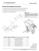
9. Position the Tow Bar under the Crossmembers with the Shear Pin Label on
top and toward the front (Figure 10).
10. Secure the front of the Tow Bar with a 1/2-13 x 6" Bolt (with Washer), Rail
Center Spacer (inserted into Crossmember), Tooth Bar Spacer (between
Tow Bar and Tooth Bar) and 1/2" Locknut (with Washer) only hand tight for
now (Figure 12).
11. Secure the rear of the Tow Bar with a 1/2-13 x 3-3/4" Bolt (with Washer),
Rail Center Spacer (inserted into Crossmember) and 1/2" Locknut (with
Washer). Tighten with two 3/4" Wrenches.
12. Tighten the Hardware you installed in step 10 with Two 3/4" Wrenches.
Note: The 1/2" Bolt and Locknut that you tightened in step 11 and 12 should be
very tight so the parts are compressed together for strength.
13. Tighten the Hardware you installed in step 5 with Two 9/16" Wrenches.
14. Return the Mold Board to its original position and install the Bolts, Flat
Washers and Locknuts that you removed. Tighten the Mold Board
hardware using two 9/16" Wrenches.
15. Install the two Hitch Adjustment Brackets with a 3/8-16 x 2-1/2" Bolt,
Locknut and Hair Pin Lanyard at the forward location using two 9/16"
Wrenches (Figure 13). Secure the rear location with a 3/8-16 x 2-1/2" Bolt
and Locknut using two 9/16" Wrenches.
Locknut
Figure 12
Locknut
Rail Center
Spacers
Bolt
Tooth Bar
Spacer
Tow Bar
Bolt
Cable
Bushing
Mold Board
Figure 11
Remove
Loosen
Crossmembers
Figure 10
Tow Bar
Shear Pin
Labe
l
Bolts and
Locknuts
Figure 9
Tooth Bar
Hitch
adjustment
Brackets
Figure 13
Hair Pin Lanyard
Tow Bar
Front Hardware
Rear
Hardware

10 DR
®
POWER GRADER
16. Position the Pin Hitch Assembly between the Hitch Adjustment Brackets
and secure with two Snap Safety Pins (Figure 14).
17. Secure the Sliding U-Bolt Backing Plate to the right side of the Tow Bar
(three holes facing forward) with two Post U-Bolts and four 3/8" Locknuts
using a 9/16" Wrench. Do not over tighten (Figure 15).
18. Install the Crank Post onto the Sliding U-Bolt Backing Plate with two 3/8-16
x 2-1/2" Bolts and Locknuts using two 9/16" Wrenches (Figure 16).
Note: The other two holes at bottom of the Crank Post can be used for height
adjustment as described in the “Crank Post Adjustment” section at the end of this
Chapter.
19. Attach the Height Adjust Control Box to the Crank Post with two 3/8-16 x 1-
1/2" Bolts, Lock Washers and Flat Washers using a 9/16" Wrench (Figure
17).
20. Insert a 3/8-16 Nut onto the threaded portion of the Crank Handle (about
3/4 of the way). Insert the Crank Handle into the hole at the top of the
Height Adjuster Control box and secure with another a 3/8-16 Nut using a
9/16" Wrench.
Note: Hold the Handle upright as you tighten the Nut against the Control Box hex.
Crank Post
Figure 16
Two Holes
Facing
Forward
Sliding U-Bolt
Backing Plate
Bolts and
Locknut
s
Sliding U-Bolt
Backing Plate
Figure 15
Post U-Bolts
and Locknut
s
Holes
Forward
Tow Bar
Pin Hitch
A
ssembly
Figure 14
Snap Safety
Pins
Height Adjust
Control Box
Figure 17
Bolt, Lock
Washer and
Flat Washer
Nuts
Crank
Handle

CONTACT US AT www.DRpower.com 11
21. Secure the back side of the two Axle Brackets to the rear Crossmember with
two 3/8-16X 3/4" Bolts (with Washers) and Locknuts (with Washers) using
a Ratchet, Extension and 9/16" Socket on the inside and a 9/16" Wrench on
the inside (Figure 18).
22. Secure the top of the Axle Brackets with two 3/8-16 X 2-1/2" Bolts (with
Washers), Rail Spacers (inserted into crossmember) and Locknuts (with
Washer) using two 9/16" Wrenches.
23. Install a 1/2" X 3/8"L, 3/8-16 Shoulder Bolt (head facing left, towards
outside of machine) and Locknut to the left side Axle Bracket using a 1/4"
Allen Wrench and 9/16" Wrench (Figure 19).
24. Repeat step 23 for the right side Axle Bracket with the Shoulder Bolt facing
right, towards outside of the machine.
25. Position the Axle Assembly on the outside of the Axle Brackets (Figure 20).
Align the top holes of the Axle Brackets to the holes in the Axle Assembly
and secure with 1/2" X 3/8"L, 3/8-16 Shoulder Bolts (head facing out) and
Locknuts using a 1/4" Allen Wrench and 9/16" Wrench.
26. Place a .8" ID, 1.5" OD x .11" Washer onto both ends of the Axle Assembly.
27. Install a Wheel and .8" ID, 1.5" OD x .11" Washer on each end of the Axle
and secure with a Cotter Pin using Pliers to bend the ends (Figure 21).
Wheel
Figure 21
Grease
Fitting
Washer
Cotter Pin
A
xle
A
ssembly
Figure 20
Shoulder Bolt
Washer
Left Side
A
xle Bracket
Shoulder Bolt
and Locknut
Figure 19
A
xle Bracket
Figure 18
Bolts and
Locknut
s
Bolts, Rail Spacers and Locknuts
Rear
Crossmembe
r

12 DR
®
POWER GRADER
28. Install the Cable Spring Bracket onto the Axle Assembly with two 3/8-16 X
2" Bolts, Washers and Locknuts using two 9/16" Wrenches (Figure 22).
29. Insert the Height Adjust Cable under the front Crossmembers a position it
near the Cable Bushing (Figure 23).
30. Pull the Rubber Cap from the threaded Rod of the Cable Assembly and
unscrew the rear Jam Nut to remove it from the Threaded Rod.
31. Position the Cable into the Bushing slot and push the Threaded Rod into
the Bushing hole.
32. Adjust the front Jam Nut that is still on the Threaded Rod until the Eyelet at
the eyelet end of the Cable can be secured to the Cable Spring Bracket with
the 5/16" X 3" Snap Safety Pin (Figure 24).
33. Reinstall the Jam Nut and secure the Cable to the Bushing by tightening the
two Jam Nuts against the Bushing using two 1/2" Wrenches (Figure 25).
34. Reposition the Rubber Cap onto the end of the Threaded Rod.
35. Secure the Cable to the Tow Bar using the Cable Tie (Figure 26).
Height Adjust
Cable
Figure 26
Tow Bar
Cable Tie
Cable
Bushing
Figure 25
Rear Jam Nut
Front Jam Nut
Rubber
Cap
Snap Safety Pin
Figure 24
Cable Eyelet
Cable Sprin
g
Bracket
Cable
Bushing
Slot
Figure 23
Rear
J
am Nut
Front
J
am Nut
Rubber
Cap
Cable
Threaded
Rod
Cable Spring
Bracket
Figure 22
3/8-16 X 2" Flange
Bolts and Locknuts
A
xle
A
ssembly

CONTACT US AT www.DRpower.com 13
Installing the Tow Hook Hitch (Ball Hitch Towing)
1. Insert the square portion of the Tow Hook Hitch into the opening of the
Tow Bar Hitch (Figure 27).
2. Insert the Shear Pin down through the Tow Bar Hitch and Tow Hook Hitch.
3. Place the Tow Hook Anti Rotation Bracket under the Tow Bar Hitch with the
hole over the bottom of the Shear Pin (Figure 28).
4. Insert the Hair Pin that is attached to the Lanyard, into the Shear Pin hole
to secure.
Connecting the DR POWER GRADER to your Tow Vehicle
The following procedure is for connecting the DR POWER GRADER to your Tow
Bar (Tractor) or Ball Hitch (ATV) configuration.
Lawn Tractor: (Tow Bar Hitch)
1.
Stop the Lawn Tractor Engine and set the Parking Brake on your Lawn
Tractor.
2. Lift the Tow Bar and position the Tow Bar Hitch opening onto the Lawn
Tractor Hitch Plate (Figure 29).
3. Align the hole in the center of the Hitch Plate on your Lawn Tractor with the
holes in the Tow Bar Hitch. Insert the Shear Pin and secure it with the Hair
Pin Lanyard.
ATV: (Tow Hook Hitch)
1.
Stop the ATV engine, put the transmission in 1st gear and set the Parking
Brake on your ATV
2. Lift the Tow Bar and position the Tow Hook Hitch over the Hitch Ball on
the ATV (Figure 30). Pull back on the Power Grader so the slot in the
Keyhole Hitch fits around the Hitch Ball Shaft.
Tow Hook
Hitch
Figure 30
Tow Ball
Tow Bar
Hitch
Figure 29
Hitch
Plate
Shear
Pin
Hair Pin
Lanyard
Tow Hook Anti
Rotation Bracket
Figure 28
Hair Pin
Tow Hook
Hitch
Figure 27
Tow Bar
Hitch
Shear Pin
Use only the shear pin provided; use of any other Shear Pin or bolt may
cause damage to your DR Power Grader.
There are two extra shear pins provided. Store one with your Operators
manual in a safe location and keep one with you when grading.

14 DR
®
POWER GRADER
Crank Post Adjustment
The Crank Post can be adjusted to fit the Lawn Tractor or All Terrain Vehicle you will be using to tow the Power Grader. The Post
can be moved forward or back on the Tow Bar as needed so the operator has easy access and no part of the Tow Vehicle will
contact the Grader while turning. The angle/height of the Crank post can be adjusted for better operator access.
SETTING CRANK POST DISTANCE FROM TOW HITCH
Tools Needed:
9/16" Wrench
1. Loosen the Locknuts that secure the U-Bolts using a 9/16" Wrench (Figure
31).
2. Move the Sliding U-Bolt Backing Plate to a position where it will not contact
any part of the Tow Vehicle while turning.
3. Retighten The U-Bolt Locknuts.
SETTING CRANK POST ANGLE/HEIGHT
Tools Needed:
Two 9/16" Wrenches
Angle:
1. Remove the upper hardware that secures the Crank Post to the Backing
Plate and loosen the lower hardware using two 9/16" Wrenches (Figure 32).
2. Align the holes at the desired angle position and reinstall the upper
hardware and tighten the lower hardware.
Height:
1. Remove the hardware that secures the Crank Post to the Backing Plate and
using two 9/16" Wrenches (Figure 32).
2. Align the holes at the other height position and reinstall the hardware.
Crank Post
Figure 32
A
ngle
Settings
Height Settings
Figure 31
U-Bolts
Sliding U-Bolt
Backing Plate
Crank Post

CONTACT US AT www.DRpower.com 15
Chapter 3: Operating The DR POWER GRADER
It may be helpful to better familiarize yourself with the features of your Grader by reviewing Figure 2 in Chapter 2 before beginning
the steps outlined in this chapter.
Operating Safety
Operating Parameters
There are four different types of tow vehicles recommended for the DR POWER GRADER. Each vehicle type has specific strengths,
weaknesses, and operating parameters when used with the DR POWER GRADER.
Garden Tractor/Lawn Tractor
14 HP and/or 400-pound tractor minimum for the 48" Model.
5 slopes or less.
Material loosened during grading increases traction difficulties.
Very good speed control and turning radius.
Frequent Scarifying Teeth adjustment may be necessary to maintain traction
Forward motion of the DR POWER GRADER may need to be initiated before ground contact.
ATV
Traction issues are less evident.
More difficult to maintain a consistent speed of less than 5 MPH.
Turning radius is large (best used for large, straight drives).
UTV
Traction issues are less evident.
More difficult to maintain a consistent speed of less than 5 MPH.
Turning radius is large (best used for large, straight drives).
The tailgate should be lowered for best visibility.
Utility Tractor
Traction is excellent.
Visibility is very good.
With the increased power, the chance of accidentally damaging the DR POWER GRADER’s frame is increased. The
towing speed MUST be kept less than 5 MPH.
Extend the Tow Bar to the longest setting when using the DR POWER GRADER with a Utility Tractor.
Not for use with Truck or Car
Do not use these types of vehicles; the DR POWER GRADER is difficult to see.
NEVER operate the DR POWER GRADER with a Truck (2WD or 4WD). Use of a Truck will void the DR POWER GRADER
Warranty.
Never allow anyone to operate the DR Power Grader without first reading and understanding all instructions in this manual.
Be thoroughly familiar with the controls and the proper use of your Grader before using.
Never let people ride on the Grader.
Always check for objects in the Grader’s path before moving.
When operating in a roadway, we suggest that you put out obstructions (marker cones or pails) to divert any traffic away from
your work area. Always be aware of potential traffic hazards.

16 DR
®
POWER GRADER
Operating Tips
Use additional weight (up to 80 pounds) by placing two Cinder Blocks between the Crossmembers when grading hard pack to
begin scarification.
Remove any added weight such as Cinder Blocks when the surface material loosens or when experiencing traction difficulties.
To create a smoother surface in soft materials, the Axle assembly can be positioned on top of the Grader to prevent tire tracks.
Remove the weights when grading in muddy conditions or sandy soil.
Expect to make several passes with the DR POWER GRADER to repair a roadway, depending on the condition.
Avoid filling Pot Holes filled with water, wait until the holes are dry.
Use the DR POWER GRADER to work the edges of Pot Holes that are more than 4 feet wide to loosen the sides before you
begin filling them.
Avoid large rocks, embedded ledge, cattle guards, or similar obstructions.
Remove rocks pulled to the surface during grading to provide a better final graded surface.
They can catch under the lawn deck (for lawn tractors).
Once you have adequately scarified the road surface, raise the Scarifying Teeth Plate to allow the Rear Scraper Blade to create a
smooth surface.
Raise the Tooth Bar Plate out of the ground before turning around or leaving the work area.
When using a lawn tractor as the tow vehicle, put the lawn mowing deck in the highest setting or just remove the deck to obtain
the highest ground clearance.
For ease, do your spring grading before re-installing your lawn deck for the summer mowing activity.
When using the DR POWER GRADER to prepare a seed bed, remove all large debris before grading.
Use the Optional Drag Screen to create the best finish in sand or to incorporate seed.
Use Low Gear when using an ATV as the tow vehicle – Do not exceed 5 MPH while grading.
The maximum speed when not grading is 10 MPH.
FAQs
Question: Can the DR POWER GRADER create a crown in the road?
Answer: No, but you can maintain a crown in the road by grading each side separately.
Question: Can the DR POWER GRADER ruin the crown in the road?
Answer: Yes, but only if you grade down the centerline of the road.
Question: Can I use my Lawn Tractor in sandy soils?
Answer: Lawn Tractors do not perform as well as an ATV or Utility Tractor in sandy soils.
Question: Why does the Hitch have a Shear Pin?
Answer: The Shear Pin will absorb the shock by breaking if you hit a large rock, ledge, or other obstruction offering some
protection to your DR POWER GRADER and Tow Vehicle.
Lower the grader frame completely to the ground surface when transporting on a trailer, parking on a hill, or servicing the grader.
Frequently check the tightness of the bolts that fasten the Tooth Bar to the frame.

CONTACT US AT www.DRpower.com 17
Adjusting the Power Grader for Grading and Scarifying
1. Rotate the Crank Knob counterclockwise until the Slider is at the bottom of
the scale to lower the machine and take all of the weight off the Wheels
(Figure 33).
Note: The Wheels must be set fully up off the ground when Grading or Scarifying.
2. Remove the Snap Safety Pins (Figure 34) and adjust the Pin Hitch
Assembly as described below:
Position the Tow Bar to the highest position for most aggressive grading
(Figure 34).
Position the Tow Bar to the lowest position for most aggressive scarifying
(Figure 35). See “Adjusting the Mold Board” for other Mold Board
settings.
Use the remaining Tow Bar Hitch mounting positions for varying degrees
of Grading and Scarifying.
Using the Mold Board
ADJUSTING THE ANGLE:
The Mold Board angle can be set at three different angles to determine how
aggressively it moves and molds the material.
Tools Needed:
Two 9/16" Wrenches
1. Remove the top Bolt and Locknut on both ends of the Mold Board using
two 9/16" Wrenches (Figure 36).
2. Loosen the Bottom Bolt and Locknut using two 9/16" Wrenches so the
Mold Board can be rotated.
3. Rotate the Mold Board to align with the holes at the desired setting.
4. Reinstall the top Bolts and locknuts and tighten all hardware.
CONVERTING TO SMOOTH OR GROOVED EDGE:
The Mold Board can be mounted with the straight edge down for basic grading
or for creating smoother surfaces in finer materials. It can also be mounted
with the grooved edge down for more aggressive grading or for creating
grooved surfaces in finer materials.
Tools Needed:
Two 9/16" Wrenches
1. Fully raise the Wheels (Figure 33) and remove the Snap Safety Pin from the
Cable Spring Bracket to rotate the Axle Assembly out of the way (Figure 37).
Crank Knob
Figure 33
Slide
r
Snap Safety Pin
Figure 37
Cable Eyelet
Cable Sprin
g
Bracket
Figure 36
Mold
Board
Remove
Loosen
2 Additional
A
djustment
Hole
s
Figure 34
Tow Bar
Snap
Safety Pins
Pin Hitch
A
ssembly
Figure 35
Tow Bar
Snap
Safety Pins
Pin Hitch
A
ssembly

18 DR
®
POWER GRADER
2. Remove the Bolts and Locknuts securing both ends of the Mold Board to
the Power Grader Frame using two 9/16" Wrenches (Figure 38).
Note: The Mold Board must always be positioned with the welded angle facing
toward the rear (Figure 39).
3. Remove the Mold Board and position it with the desired edge down and the
welded Angle facing the rear of the machine.
4. Reinstall the Mold Board and secure with the Bolts and Locknuts.
5. You can reinstall the Snap Safety Pin (Figure 37) so you can raise the
Grader when needed or you can rotate the Axle so it is resting on top of the
Grader (Figure 40) to prevent the Wheels from leaving marks in finer
materials.
Note: If you want the place the Axle on top of the Grader, you must strap it to the
Grader to keep it in place.
Adding Weight to the Weight Tray
Two Cinder Blocks can be placed between the Crosmembers to add more
weight for harder surfaces (Figure 41).
Any weights added to the top of the Grader must be strapped to the
Crossmembers to prevent them from being bounced off the machine.
Lowering the Wheels for transporting
1. Rotate the Handle clockwise to raise the Slider to the top of the scale
(Figure 42). This will lower the Wheels and lift the Power Grader off the
ground for transporting.
Cinder
Blocks
Figure 41
Crossmember
s
Figure 38
Mold
Board
Bolts and
Locknut
s
Straight Edge
Welded
A
ngle
Figure 39
Grooved Edge
A
xle and
Wheels
Figure 40
Do not add more than 80 pounds of weight to the Grader. More than 80
pounds could cause damage to the Grader and void the Warranty.

CONTACT US AT www.DRpower.com 19
Optional Drag Screen
An optional Drag Screen is available for your DR POWER GRADER. This heavy-duty, flexible-steel screen attaches easily behind
the DR POWER GRADER to break up and smooth any clumps that form as you grade the material.
The Drag Screen is also designed to produce a more highly finished surface when using fine dry materials such as sand and to
remove the small lines or ridges sometimes left by the Scarifying Teeth or Grader Wheels during the initial grading process. The
Drag Screen is ideal for areas that have high sand or soil content such as new lawns, riding rinks, ball fields, or sandy driveways.
The Drag Screen is also very helpful in seeding large areas. By lifting the Scarifying Teeth and Mold Board of the DR POWER
GRADER above the working surface so that only the wheels make contact, the Drag Screen simply and effectively distributes the
topsoil uniformly over the seed.
For more information and to order the Optional Drag Screen for your new DR POWER GRADER, contact us at www.DRpower.com
or call Toll-Free 1-800-DR-OWNER (376-9637).

20 DR
®
POWER GRADER
Chapter 4: Maintaining The DR POWER GRADER
Regular maintenance is the way to ensure the best performance and long life of your machine. Please refer to this Chapter for
maintenance intervals and procedures.
Regular Maintenance Checklist
P
ROCEDURE BEFORE EACH USE EVERY 25 HOURS
Check general equipment condition e.g., Nuts, Bolts, welds, etc.
▲
Hose down the DR POWER GRADER
▲
Check condition of Shear Pin
▲
Lubricate Wheels as needed
Cleaning the Power Grader
1.
Use a Hose or Pressure Washer to clean the DR POWER GRADER to keep the Scarifying Teeth Plate, Wheels etc. clean and
clear of debris.
Checking the Shear Pin
1. Check the Shear Pin for signs of wear or damage. Replace the Shear Pin if worn or damaged.
Replacing the Tooth Bar
Tools Needed:
Two 9/16" Wrenches
1. Use the Height Adjust to lower the Wheels to raise the front of the DR
POWER GRADER off the ground.
2. Remove the Bolts and Locknuts on both ends of the Tooth Bar using two
9/16" Wrenches (Figure 43).
3. Remove the old Tooth Bar and clean the mounting area of the Frame.
4. Position the new Tooth Bar and secure with the Bolts and Locknuts.
Lubrication
Tools and Supplies Needed:
Flexible hose grease gun
Lithium grease
Clean Rags
1. Clean the Grease Fitting with a clean Rag (Figure 44).
2. Lubricate the Wheels at the grease fitting every 25 hours of operation.
Note: Pump the grease gun only until you feel slight resistance (2 - 3 pumps).
Before performing any maintenance, you must first shut off the tow vehicle, remove the key and set the parking brake.
Tooth Bar
Figure 43
Bolts and
Locknuts
Wheels
Down
Grease
Fitting
Figure 44
/