Page is loading ...

G‐SPOT
MOVINGHEAD
Manual_G_Spot_EN_170x113,3.book Page 1 Tuesday, June 9, 2015 10:22 AM

2
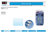
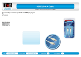
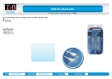
Dimensions
135°
270° 270°
805
(31.7)
646
(25.4)
494
(19.5)
144
(5.7)
327
(12.9)
821
(32.3)
Min. c/c
764
(30.0)
492
(19.4)
470
(18.5)
664
(26.2)
135°
340
(13.4)
370
(14.6)
16 (0.63)
37 (1.46)
Measurements in millimetres
and inches (in parentheses).
Drawing not to scale.
Manual_G_Spot_EN_170x113,3.book Page 2 Tuesday, June 9, 2015 10:22 AM

3
G‐SPOT
USERMANUAL
© 2015 SGM
®
. Information subject to change without notice. SGM and all
affiliated companies disclaim liability for any injury, damage, direct or indirect loss,
consequential or economic loss or any other loss occasioned by the use of,
inability to use or reliance on the information contained in this manual.
The SGM logo, the SGM name and all other trademarks in this document
pertaining to services or products by SGM or its affiliates and subsidiaries are
trademarks owned or licensed by SGM or its affiliates or subsidiaries.
The original edition of this document is in English. All other language editions are
translations of the original edition.
This edition applies to firmware version 1.00 or later.
Ver. F
Manual_G_Spot_EN_170x113,3.book Page 3 Tuesday, June 9, 2015 10:22 AM

4
Dimensions ................................................................................................................... 2
Safety information ......................................................................................................... 7
Overview ..................................................................................................................... 10
Unpacking ................................................................................................................... 11
Transportation ..........................................................................................................................................................11
Installation / Rigging .................................................................................................... 12
Connecting AC power ................................................................................................. 14
Control panel operations ............................................................................................. 15
Using the control panel ............................................................................................................................................15
DMX start address ...................................................................................................................................................15
Selecting module (G-Spot or G-Profile) ...................................................................................................................15
Configuring the device using an Android telephone via RFID..................................................................................16
Connecting to a DMX control device ........................................................................... 17
Contents
Manual_G_Spot_EN_170x113,3.book Page 4 Tuesday, June 9, 2015 10:22 AM

5
Configuring the device for DMX control ...................................................................... 18
About DMX...............................................................................................................................................................18
Setting the DMX address .........................................................................................................................................18
Control panel menus ................................................................................................... 19
Gobo replacement ....................................................................................................... 28
Identification of gobo wheel......................................................................................................................................28
Replacing rotating gobos .........................................................................................................................................29
How to replace a gobo in a gobo holder ..................................................................................................................30
Maintenance ................................................................................................................ 31
Upgrading the firmware............................................................................................................................................31
Cleaning ...................................................................................................................................................................31
DMX protocols ............................................................................................................. 32
24 Channel Mode (Standard)...................................................................................................................................32
30 Channel Mode (Extended) ..................................................................................................................................44
Full Color Calibration and Color Temperature Correction........................................................................................56
Manual_G_Spot_EN_170x113,3.book Page 5 Tuesday, June 9, 2015 10:22 AM

6
Effects ......................................................................................................................... 57
Two independent rotating gobo wheels ................................................................................................................... 57
Effect wheels ........................................................................................................................................................... 57
High-precision pan and tilt ....................................................................................................................................... 57
Ultra high-speed strobe effect.................................................................................................................................. 57
Prism........................................................................................................................................................................ 57
Frost......................................................................................................................................................................... 57
Fixtures and accessories ............................................................................................ 58
Included items.......................................................................................................................................................... 58
Ordering information ................................................................................................................................................ 58
User’s notes ................................................................................................................ 60
Manual_G_Spot_EN_170x113,3.book Page 6 Tuesday, June 9, 2015 10:22 AM

7
Safety information
The G-SPOT is intended for professional use only. It is not suitable for household use. Impropre a l’usage domestique.
Review the following safety precautions carefully before installing or operating the fixture. This product must be installed in
accordance with the applicable installation code by a person familiar with the construction and operation of the product and
the hazards involved. Ce produit doit être installé selon le code d’installation pertinent, par une personne qui connaît
bien le produit et son fonctionnement ainsi que les risques inhérent.
Preventing electric shock
• Always power off/unplug the fixture before removing covers or dismantling product.
• Ensure that the mains power is off when wiring the fixture to the AC mains supply.
• Ensure that the fixture is electrically connected to earth (ground).
• Do not apply power if the fixture is in any way damaged.
• Do not immerse the fixture in water or liquid.
WARNING! Read the safety precautions in this section before
unpacking, installing, powering or operating this product.
WARNING! Risk of electric shock.
Manual_G_Spot_EN_170x113,3.book Page 7 Tuesday, June 9, 2015 10:22 AM

8
Preventing burns and fire
• Install in a location that prevents accidental contact with the fixture.
• Install only in a well-ventilated space.
• Install at least 0.3 m (12 in.) away from objects to be illuminated.
• Install only in accordance with applicable building codes.
• Ensure a minimum clearance of 0.1 m (4 in.) around the cooling fans.
• Do not paint, cover or modify the fixture.
• Keep all flammable materials away from the fixture.
• Allow the fixture to cool for 15 minutes after operation, before touching it.
CAUTION: Exterior surface temperature after 5 min. operation = 55° C (131° F). Steady state = 65° C (149° F)
WARNING! Take measures to prevent burns and fire.
Manual_G_Spot_EN_170x113,3.book Page 8 Tuesday, June 9, 2015 10:22 AM

9
Avoid personal injury
• Do not look directly at the light source from close range.
• Take precautions to prevent injury when working at height.
• Ensure that the fixture is always securely fastened with suitable hardware.
• For elevated installations, secure the fixture with suitable safety cables, and always comply with relevant load
dimensioning, safety standards and requirements.
WARNING! Take measures to prevent personal injury.
Manual_G_Spot_EN_170x113,3.book Page 9 Tuesday, June 9, 2015 10:22 AM

10
Overview
J
I
H
F
K
E
FC
A
C
D
G
B
The SGM G-Spot model is a maintenance free, multi-environmental fixture with an
IP-rating of 65. It has a powerful LED light source, and a virtually unlimited color palette,
two independent rotating gobo wheels and can easily be controlled by wired and wireless
DMX. The fixture also offers RFID and NFC, low power consumption and an expected
lifetime of the multiple LED’s of 50,000 hours*.
A : Pan lock
B:Tilt lock
C : Base handle
D : Head fan grill (one of two shown)
E : Display panel
F : Safety wire attachment point
G:Fuse
H:DMX in
I : DMX out
J:Power in
K : Power cord
* At 70% of luminous output under the manufacturer’s test conditions.
Manual_G_Spot_EN_170x113,3.book Page 10 Tuesday, June 9, 2015 10:22 AM

11
Unpacking
Unpack the fixture and inspect it to ensure that it has not been damaged in transport.
The G-Spot is supplied with:
• User manual.
• One Neutrik TRUE1 power input connector, 2 m (78 in.)
• Two Omega brackets with 1/4-turn fasteners.
The fixture is designed for use in wet locations and is IP65-rated. When selecting a location for the fixture, ensure that:
• it is situated away from public throughfares and protected from contact with people.
• it has adequate ventilation.
Transportation
Always use the supplied packaging for transportation and storage.
Release the pan/tilt locks when transporting the fixture. Leaving the pan/tilt locks applied may cause damage to the
fixture.
Manual_G_Spot_EN_170x113,3.book Page 11 Tuesday, June 9, 2015 10:22 AM

12
Installation / Rigging
WARNING! Always secure elevated fixtures with a safety cable.
The G-Spot may be installed in any orientation.
Always use two Omega brackets to rig the fixture. Lock each
bracket with both 1/4-turn fasteners. The fasteners are locked only
when turned fully clockwise.
Always fasten safety cables between the load-bearing support
structure and the attachment points on the fixture. The safety
cables must be able to bear at least 10 times the weight of the
fixture.
CAUTION:
• Always use two safety wires.
• Min. safety wire gauge = 5 mm.
• Max. safety wire length (free fall) = 30 cm (11 in.)
• Make sure the slack of the safety wire is at a minimum.
• Never use the carrying handles for secondary attachment.
Manual_G_Spot_EN_170x113,3.book Page 12 Tuesday, June 9, 2015 10:22 AM

13
Start the rigging process by blocking the work area below, and make sure the work is performed from a stable platform.
1 Check that the clamps are undamaged and can bear at least 10 times the weight of
the fixture. Check that the structure can bear at least 10 times the weight for all
installed fixtures, clamps, cables etc.
2 Bolt each clamp securely to an Omega bracket with an M12 / ½” bolt (min. grade 8.8)
and lock nut.
3 Align an Omega bracket with two 1/4-turns in the base. Insert the fasteners into the
base and turn both levers a full 1/4-turn clockwise to lock. Install the second Omega
bracket.
4 Working from a stable platform, hang the fixture on a truss, or other structure. Note
the position of the base. The front of the base is to the right, when looking at the dis-
play panel, and when the fixture is sitting on the base. Tighten the clamps.
5 Install two safety wires that each can bear at least 10 times the weight of the unit.
The attachment points are designed to fit a carabiner.
6 Check that the pan/tilt locks are released (A and B). Verify that there are no
combustible materials or surfaces to be illuminated within 0.3 m (11 in.) of the
fixture.
7 Check that there is no possibility of head or yoke colliding with other fixtures.
FRONT
Manual_G_Spot_EN_170x113,3.book Page 13 Tuesday, June 9, 2015 10:22 AM

14
Connecting AC power
The G-Spot can operate on any 200-240V, 50/60 Hz mains power supply
Connect the fixture to power using a cable with a Neutrik powerCON TRUE1
connector (supplied with the fixture). Connect both DMX in and DMX out
cables in order to maintain the fixture IP65.
Fuse Power
In
DMX
In
DMX
Out
The fixture must be grounded/
earthed and be able to be isolated
from AC power. The AC power
supply must incorporate a fuse or
circuit breaker for fault protection.
Manual_G_Spot_EN_170x113,3.book Page 14 Tuesday, June 9, 2015 10:22 AM

15
Control panel operations
You can configure individual fixture settings, read out data and view error messages in the graphic display.
When the fixture is powered on, it boots and resets, then displays the DMX start address and any status messages.
Using the control panel
• Click the arrow buttons to scroll up and down menus.
• Click the OK button to enter a menu or make a selection.
• Press the ESC button to step backwards through the menus.
DMX start address
The DMX start address is the first channel used to receive instructions from the controller. For independent control, each
fixture must be assigned its own start address. If you give two fixtures the same address, they will behave identically. Address
sharing can be useful for diagnostic purposes and symmetrical control.
Select DMX address using the arrow buttons.
Selecting module (G-Spot or G-Profile)
If you replace the fixture’s module in order to switch from a G-Spot to a G-Profile or vice-versa, you need to change the fixture’s
software settings.
In the Control Menu, go to ‘Settings→Service Menu→Fixture Type” and select the fixture you are currently using.
NOTE: To access “Service Menu→Fixture Type”, you need to type in the value ‘0110’ under ‘Settings→Service Pin”.
See “Control panel menus” on page 19 for more details.
ESC.
OK
Manual_G_Spot_EN_170x113,3.book Page 15 Tuesday, June 9, 2015 10:22 AM

16
Configuring the device using an Android telephone via RFID
The G-Spot can also be configured wirelessly, via RFID, using the SGM Tool app installed on an Android smart phone that
has NFC support (ISO 15693 and ISO 18000-3 mode 1 compatible, operating on 13.56 MHz ±7k Hz carrier frequency).
Manual_G_Spot_EN_170x113,3.book Page 16 Tuesday, June 9, 2015 10:22 AM

17
Connecting to a DMX control device
The G-Spot is controllable using a DMX control device and it can be connected using either a DMX cable or via the fixture’s
built-in LumenRadio CRMX wireless receiver system.
If using a cabled DMX system, connect the DMX in cable (with male 5-pin XLR plug) and out cable (with female 5-pin XLR
plug) to the DMX data link. Terminate the DMX out cable of the last fixture in the data link. For outdoor installations, use only
IP-rated XLR connectors suitable for outdoor use.
Manual_G_Spot_EN_170x113,3.book Page 17 Tuesday, June 9, 2015 10:22 AM

18
Configuring the device for DMX control
About DMX
The G-Spot can be controlled using signals sent by a DMX controller on a number of channels (which varies depending on
the DMX mode that has been set).
The first channel used to receive data from a DMX control device is known as the DMX start address. Each G-Spot must have
a DMX start address set. For example, if a fixture has a DMX address of 10 and it is in 3-channel DMX mode, then it uses
channels 10, 11, and 12. The following device in the DMX chain could then be set to a DMX address of 13. If two or more
DMX devices of the same type have the same DMX address, then they will mimic each other’s behavior. Incorrect settings
will result in unpredictable responses to the lighting controller.
Setting the DMX address
The DMX address can be seen on the OLED display. To change the address setting, press the up and down arrows. When
the desired address is displayed, press ‘OK’ to save the setting. For your convenience, the suggested DMX address of the
next device is displayed to the right. Note that channel spacing is determined by the DMX mode.
See the “DMX protocols” on page 32 for specific DMX control values
Manual_G_Spot_EN_170x113,3.book Page 18 Tuesday, June 9, 2015 10:22 AM

19
Control panel menus
Level 1 Level 2 Level 3 Level 4 Info
DMX MODE STANDARD
EXTENDED
INFO GENRAL INFO PRODUCT:
SN:
RDM LABEL
RDM ID
SOFTWARE
VERSION
MAIN:
SMPS:
PAN:
TILT:
GOBO:
ZOOM:
Manual_G_Spot_EN_170x113,3.book Page 19 Tuesday, June 9, 2015 10:22 AM

20
INFO
(continued)
TIMERS RED
GREEN
BLUE
RUNNING HOURS
D: H:
D: H:
D: H:
D: H:
DMX VIEW 001 -
↓
507 -
TEMPERATURES LED
SMPS
PAN:
GOBO:
BASE:
HUMIDITY
R: G: B:
TILT:
FOCUS:
HEAD:
B: H:
Level 1 Level 2 Level 3 Level 4 Info
Manual_G_Spot_EN_170x113,3.book Page 20 Tuesday, June 9, 2015 10:22 AM
/